The Tender sole plate has already been made as described in the Tender Chassis section so the first job is to solder the base angle onto the sole plate . The angle used is 5/16″ and I will use this size for all the joints although the drawing does use 1/4″ angle in places.
I first marked the sole plate by scribing a line where the outside of the sides, front and back would finish and then cut the angle for the four lengths to a length that was short of the lines by the thickness of the sheet brass times two (18g brass in use so 2x 0.047″).
Initially I thought I would temporarily rivet the angle to the sole plate with 1/16″ copper rivets to secure the angle in place during soldering. However for the first piece of angle which was a length across the sole plate I clamped it in place having tinned the angle and the sole plate first. The tinning of the angle was done with a large iron of 175W with a 5/8″ bit and to tin the sole plate I used the same iron but used a low flame propane torch onto the bit to counteract the heat loss from iron to sole plate. The solder used was 170 degree lead free and I will come back to this shortly.
With the part clamped the iron and soft flame was used again to join the two but adding a length of solder to inside of the join which melted into the joint as I moved the iron along. Satisfied that the technique worked I next put a long side length on. More clamps were needed but the approach was the same and this time what I had feared came to pass, the sole plate ended up with a banana shape. Clearly the technique was no good for the long lengths.
The bowing was clearly due to too much heat combined with the extra length involved. Searching around for a solution I found that most people who had published their work on tenders on the internet used a much lower melting point solder and it was leaded to make for easy flowing. I have a lower melting point solder at 140 degrees so the next piece of angle to be put on will use this.
The lower melting point solder was a definite improvement. I also tried on the tender rear plate using solder paste and rather than clamping the angle to the sheet I attached it with 10 BA c/s screws every 1″ without a c/s hole as the heads would be eventually finished flush the angle being tapped rather than using nuts. This worked much better all round. The back plate grab handles were soldered on at this time too as they have to be watertight.
During all this experimental process I noticed that the tender was narrower than the loco cab according to the as drawn dimensions. This got me concerned as all the photos I had seen of the A1 seemed to have the tender at the same width as the cab. I checked my A4 and indeed its tender is narrower than the cab, I also asked club members and the general opinion was that it should be as wide as the cab. I then came across a photo of Sea Eagle in a book on Peppercorn A1’s and that appeared to have a tender narrower than the cab. Unfortunately most photo’s of loco’s always seem to be three quarter views and this was no exception so the appearance could just be a perspective issue. My conclusion was to build the tender as drawn.
With all this going on I then found that I had soldered the two long lengths of angle on the sole plate 1/8″ too narrow on each side! I must have mis read the rule. Nothing for it but to take them off and position them in the right place this time using solder paste.
Another problem troubling me was how to put the top bend in the side plates of the tender. I have no means to bend the length involved and 18g is quite stiff to put in a 1/2″ radius. After a couple of false starts I located a local sheet metal company who said they could do it for me. A few days later a call from them saying they were done and I collected them. They looked OK. Quite relieved at getting that problem solved I headed home a happy bunny only to find when I checked them against the drawing the bend had been put in too low from the top edge so the radius was in the wrong place! That was a blow. Could I perhaps straighten it out sufficiently to rectify the error, no chance, even trying to anneal the brass did not help but made the problem worse to solve as it just introduced distortion. So now two pieces of expensive brass plus the cost of having the bends put in are now scrap. Not happy.
Whilst sorting out what to do with the side plates I made a start on the rear plate. This was cut out to size on a guillotine and the top curve put on with a band saw except for the final curve that mates with the curve of the rolled side plate as I need to match the two and of course I had not got the side plates.

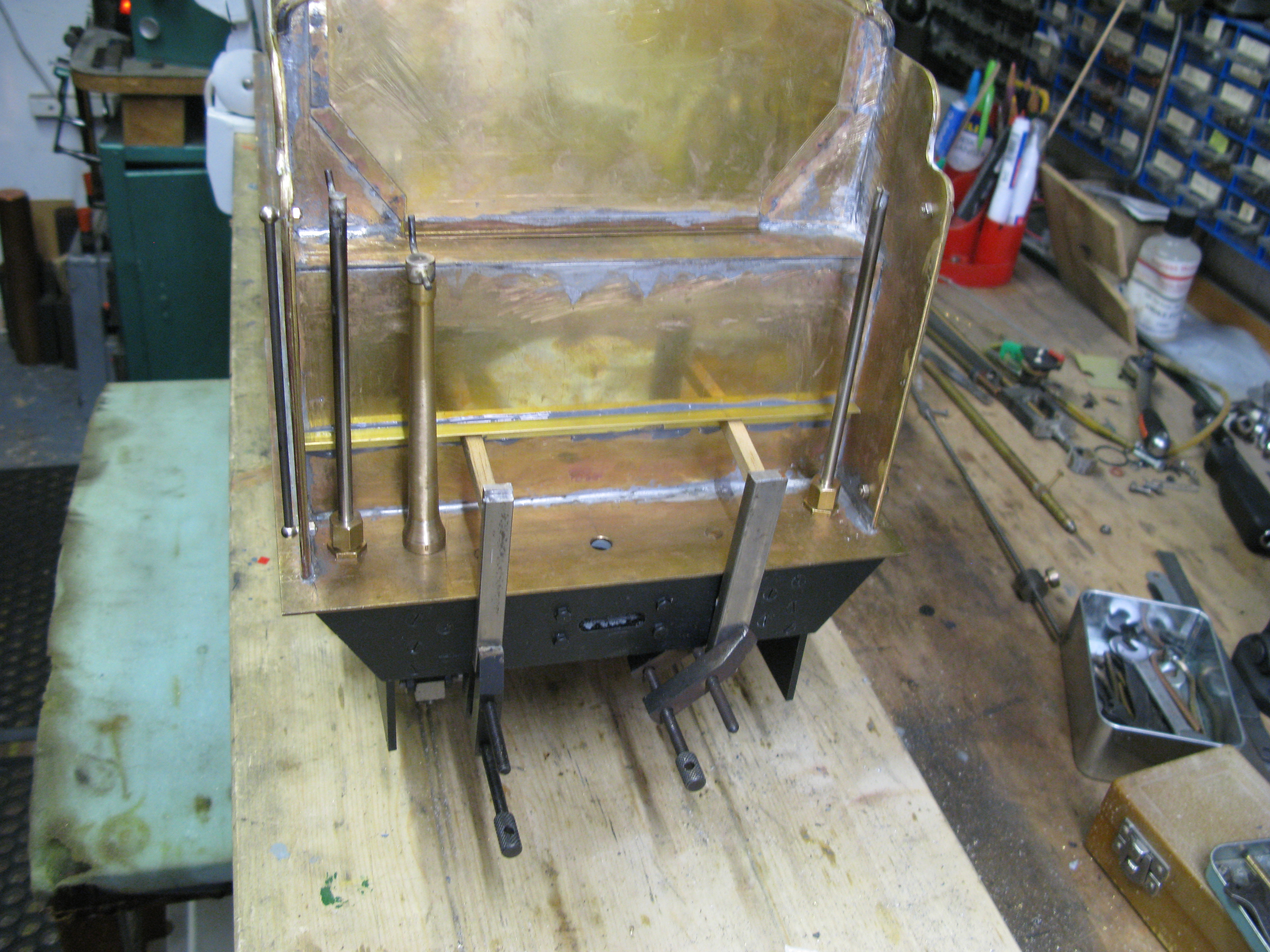
The brass angle forming the frame was soldered in position using solder paste having first screwed the plate to the angle with 10 BA c/s screws. The picture above shows the plate screwed to the bottom angle that is already soldered to the sole plate. Once the angle is soldered in position the heads of the c/s scews are filed away leaving a flush finish.
As the two side hand rails will be fiixed with their staunchions penetrating into the water space I decided to mount those so the nuts could be softsoldered to make a permanent seal.

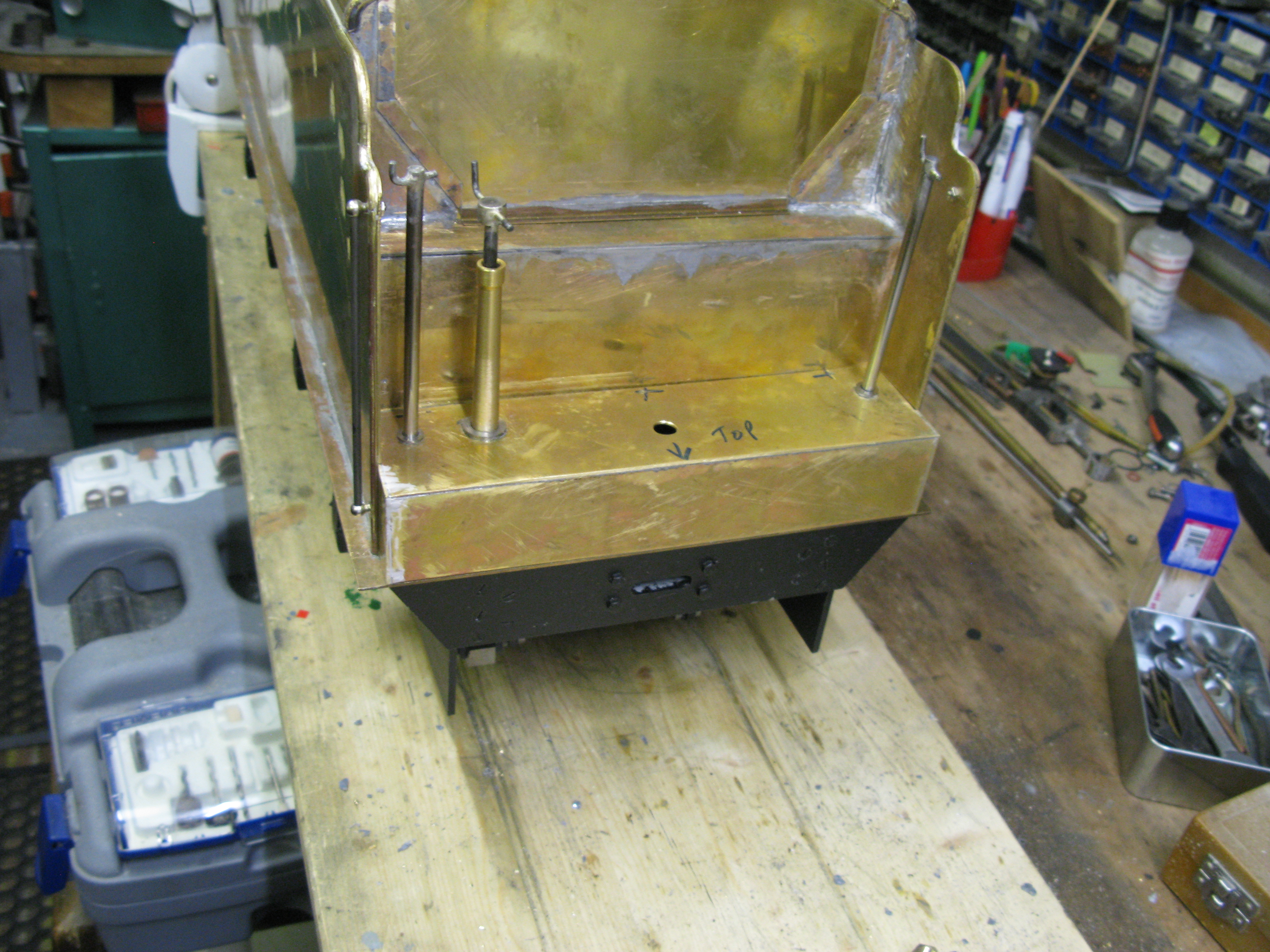
The top hand rail is level ! its the photo perspective that makes it appear drooping.
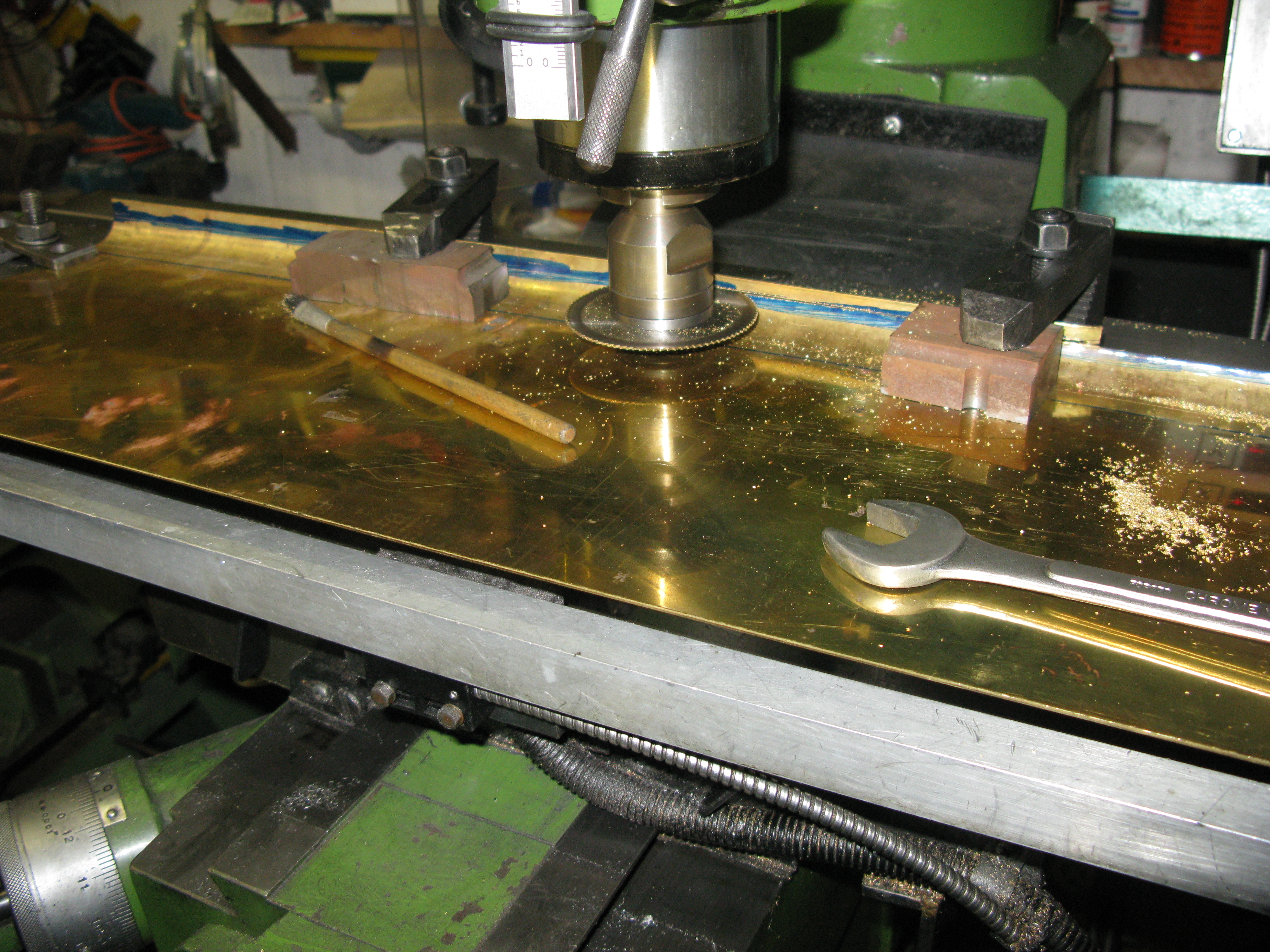
The lamp irons I have made from steel and riveted them in position. I chose to machine them from solid as the top part is only 85 thou and silver soldering it in place was going to be fiddly. It did not take long to machine out the front and rear and then slice them up.

slicing the lamp iron machined block.
The last items (but one) to go the rear plate are the steps. These were cut and bent and riveted in position with 1/16″ coper rivets.

Also in the picture above can be seen the top support angle frame which is now fixed to the rear plate. At the moment the plate is leaning forward unsupported on the sole plate. The plan is to screw the angle in position with 10 BA c/s screws and the solder it to the side plate. When that is done the final matching 1/2″ radius curve on the rear plate can be matched to the side plate and the beading applied to the rear plate top.
The side plates …….. well I had another go at straightening the bend using my 12 ton press. That worked OK for the first one I did and encouraged by that I set about putting the bend in by using a large length of 1 1/2″ x 1 1/2″ steel angle and a 1″ dia steel bar. The technique was to press the bar onto the sheet clamped across the angle so the bar and sheet went into the V. With the plate, angle and bar clamped up and in the bench vice the whole was gradually tightened by tightening the clamps and vice jaws gradually and evenly. This remarkably produced a nice bend and it just need to be trimmed to length which I did by clamping the side to the mill table and using a slitting saw to run along the whole lenth of the side, moving the clamps as the cut progressed. It just remained to trim the bottom edge of the side on the guillotine to get the right hieght.
I felt quite pleased with the result so set about on the second side to straighten the bend out.
The result was a disaster. The sheet buckled and there was no way I could get the bend out to produce a flat sheet again. So back to the drawing board.
The final solution (I hope) is to have the two sides laser cut and bent profesionally and my order is in with a delivery expected soon.
Whist kicking my heels waiting for the tender sides I decided to make a start on the hand pump.
Hand Pump
The hand pump is constructed from three castings plus other parts to be made. The castings are the main body, the pump head and the ram gland cover. The pump is quite large having a ram diameter of 5/8″.
The first job tackled was the cleaning up of the foot of the body to achieve a flat base and rectangular outline and to drill the fixing holes for mounting it to the tender sole plate. The casting was held in the mill vice to machine the flat base and outline and the drilling of the fixing holes could be done with the same set up.
The next task was machine the ram bore. I decided to do this on the mill as there was no way I could mount the casting on an angle plate in the lathe and counteract the heavy out of balance forces that would result. The set up on the mill was to clamp the pump to an angle plate and drill and then bore the hole. However what I found was that the in trying to set up the casting to be vertical the casting was in fact bowed slightly which ment that I had to find a compromise to the true vertical.

A pilot hole was first drilled right through using a long series drill. Then A larger drill and finally a 1/2″ drill. The drilling of the larger hole showed how easily it was for the drill to grab and self feed. Fortunately no damage occured. To open the bore out to 5/8″ I used a boring head and long boring bar. Using only 20 thou cuts max the bore was succesfully done to 5 thou undersize and then a 5/8″ reamer put through to fininsh the bore.

The two fixing holes for the ram gland plate were drilled at this time also.
The bore was counter bored for the gland at 3/4″ diameter and 1/4″ deep using a 3/4″ slot drill and the face squared off. I turned the pump over in the vice and squared off the face at the other end.
The next action was to drill the fin for the fixing pin that is used by the straps to conect to the pump lever.

The straps were machined from 1/8″ brass sheet using my little CNC mill. They can be seen in the photo further down the page. Nothing special about them.
The pump head is a square section 5/8″ casting. However this is too small to make it to the as drawn dimensions as it requires a 1/8″ deep 5/8 ” dia stub to fit into the pump body bore and the casting size does not allow for that. Fortuntely by making the internals of the pump head slightly smaller by 1/32″ in dia I could get the machining done OK.
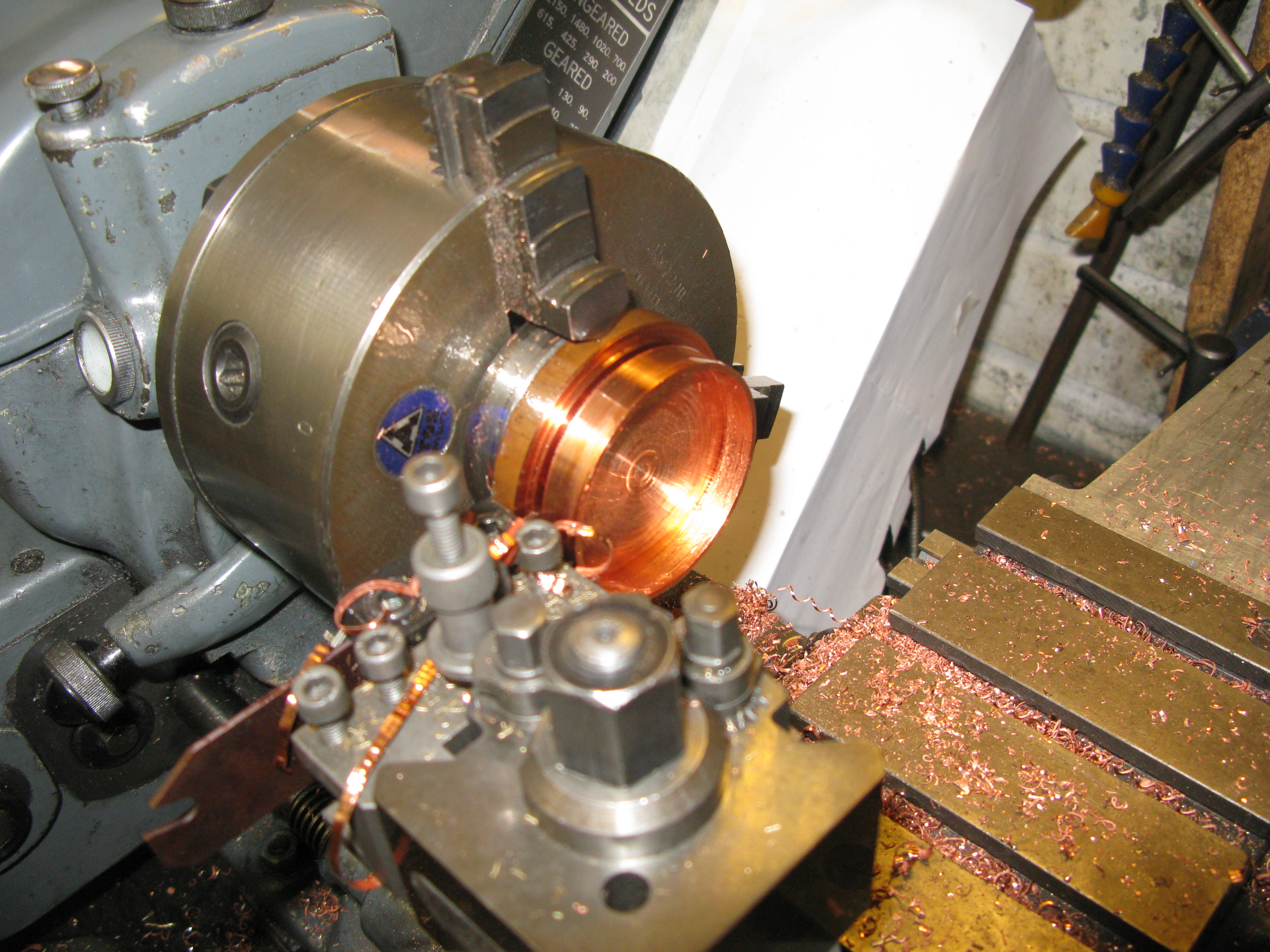
The casting was put in the independant 4 – jaw chuck for facing and turning the 5/8″ di stub as the first job.
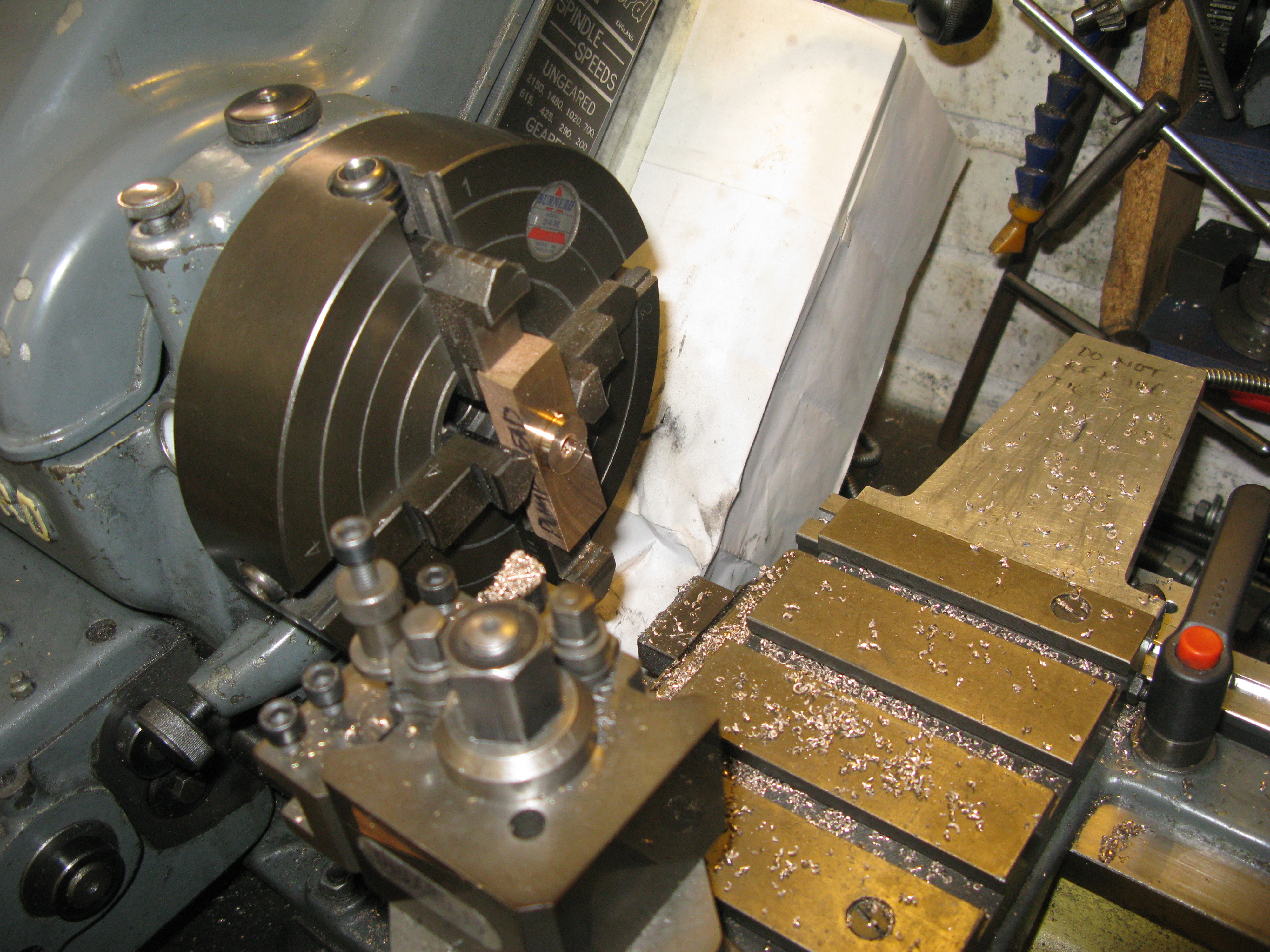
This was followed by putting the casting in the chuck lengthways to drill the through hole 3/16″ dia. With the casting blued and marked to make length to size one end was turned to length counetr bored 5/16″ and then drilled and tapped 3/8″ x 40 tpi 1/4″ deep.
The casting was turned around and the other end machined likewise.

The outlet from the pump head is to allow connection by 3/16″ copper pipe and a nipple is made to screw into the head just below the top.
The head can now be silver soldered onto the pump body.
The connections to the outlet and the pump inlet are straight forward turning jobs as is the plug at the top which has a small peg to prevent the ball rising too far and blocking the outlet.
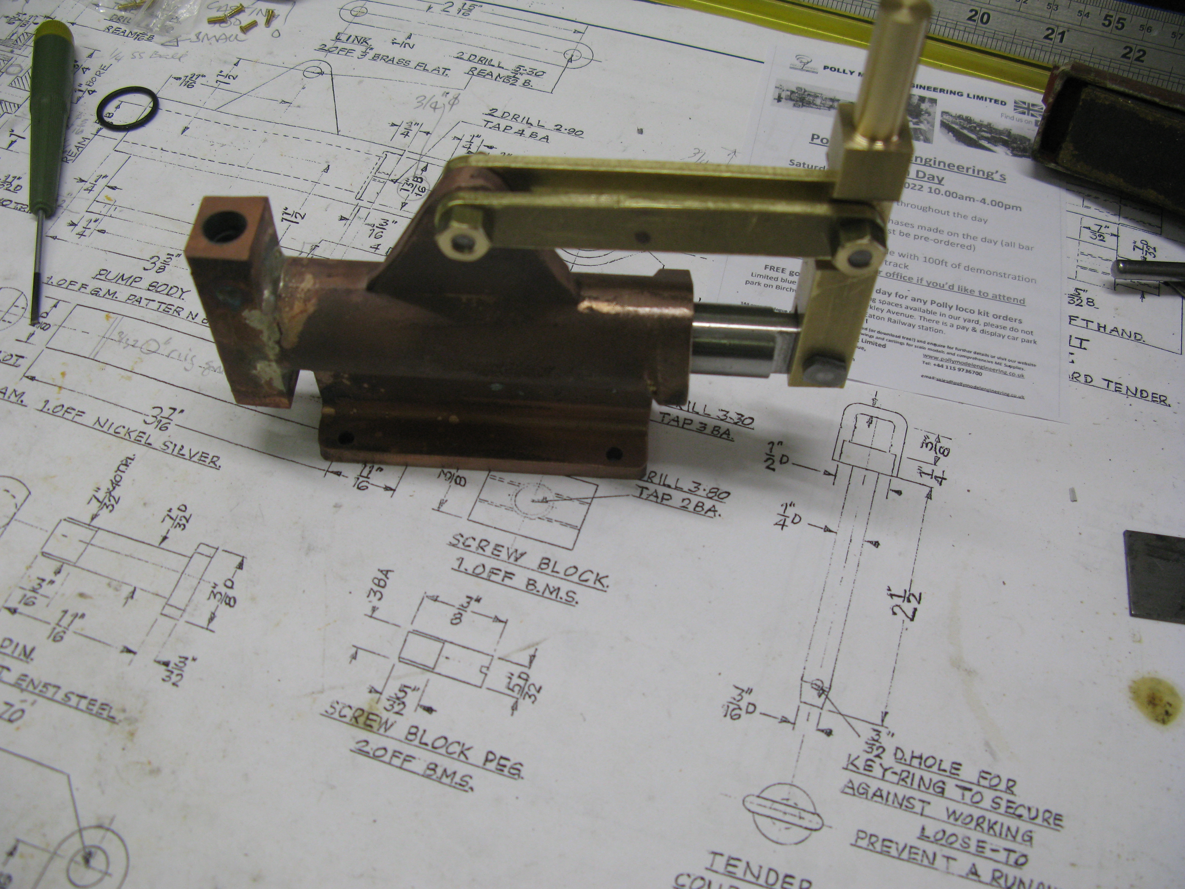
The pump ram is stainless steel and it is fitted with an O ring. The pump handle is machined from brass and not as drawn as there is a drawing error stipulating to make it from 1/8″ brass!. The finished handle is clearly seen above. An extension handle is used when driving.
The gland is machined from a casting, again nothingh special about it other than I used O rings to make the gland seal. I say plural as two are fitted as I only had small cross section O rings of the right size.

The finished pump in place. (apart from the intake filter)
A test of the pump in a bowl of water confirmed its operation OK.
Tender continued
With the delivery of the tender sides I can now crack on with its build. My process is to fix parts in place with screws prio to soldering to ensure all fit together tightly and square.
The tender sides thus needed to be screwed to the angle on the sole plate.
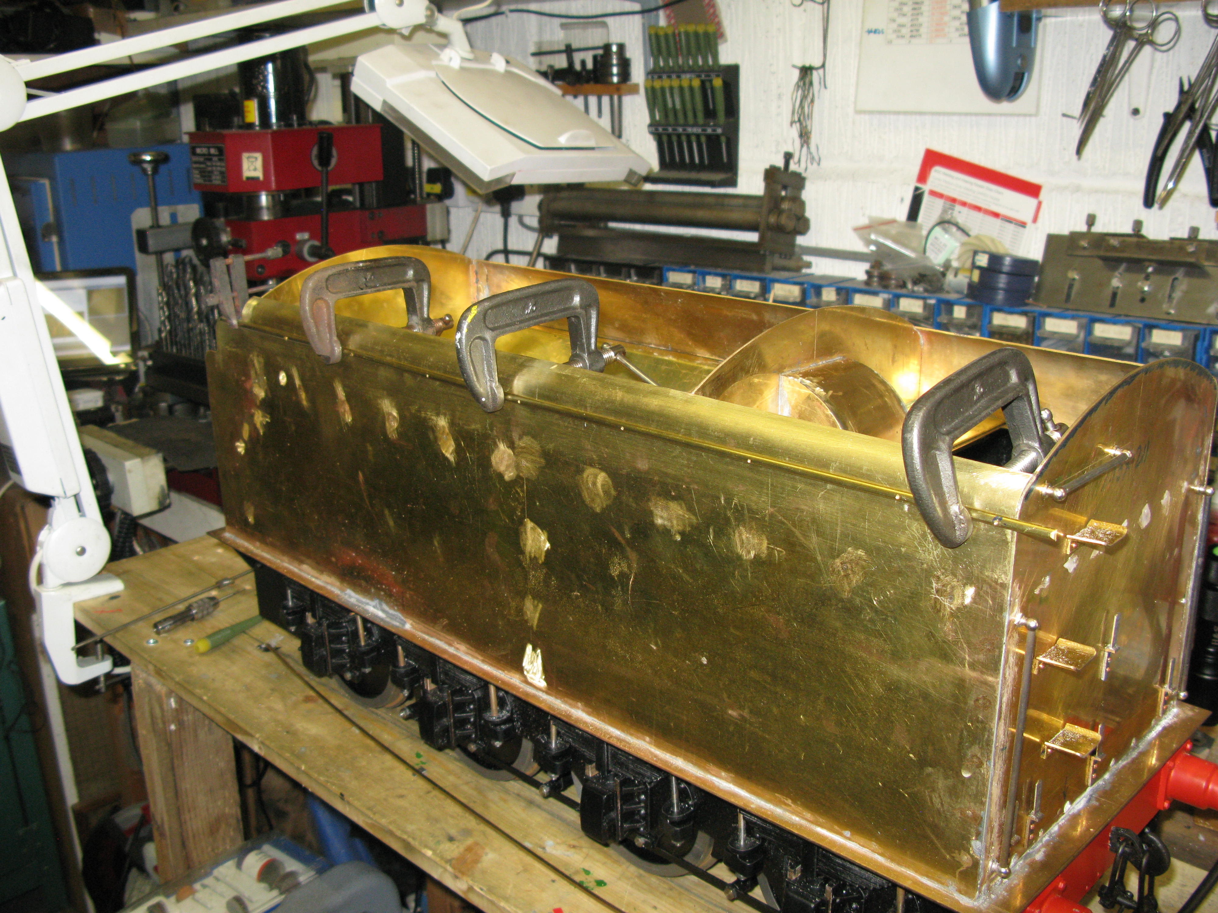
10 BA tapping holes were first drilled along the edge of the side to coincide with the angle and then the side clamped in place attached to the rear to provide some rigidity which had previously been drilled and tapped. The clamps in the photo above are pressing the side against the angle. The tapping holes were then drilled throughthe angle, the side removed and its holes opened out to clearance size followed by tapping the angle. This was done for both sides.
Next, angle was cut and trial fitted to support the internal structure. Again the process was to clamp the angle in place having drilled tapping holes in the sides and then drill through.

The method of clamping the angle for drilling is shown above. Once all the holes were done the angle could be soldered to the side. I used solder paste to do this. A large soldering iron with a gentle flame onto the bit to counteract the large heat sink of the brass side created enough heat to secure the angle.
Did you know a good flux cleaner is Isopropanol? works a treat.

internal support angle before soldering
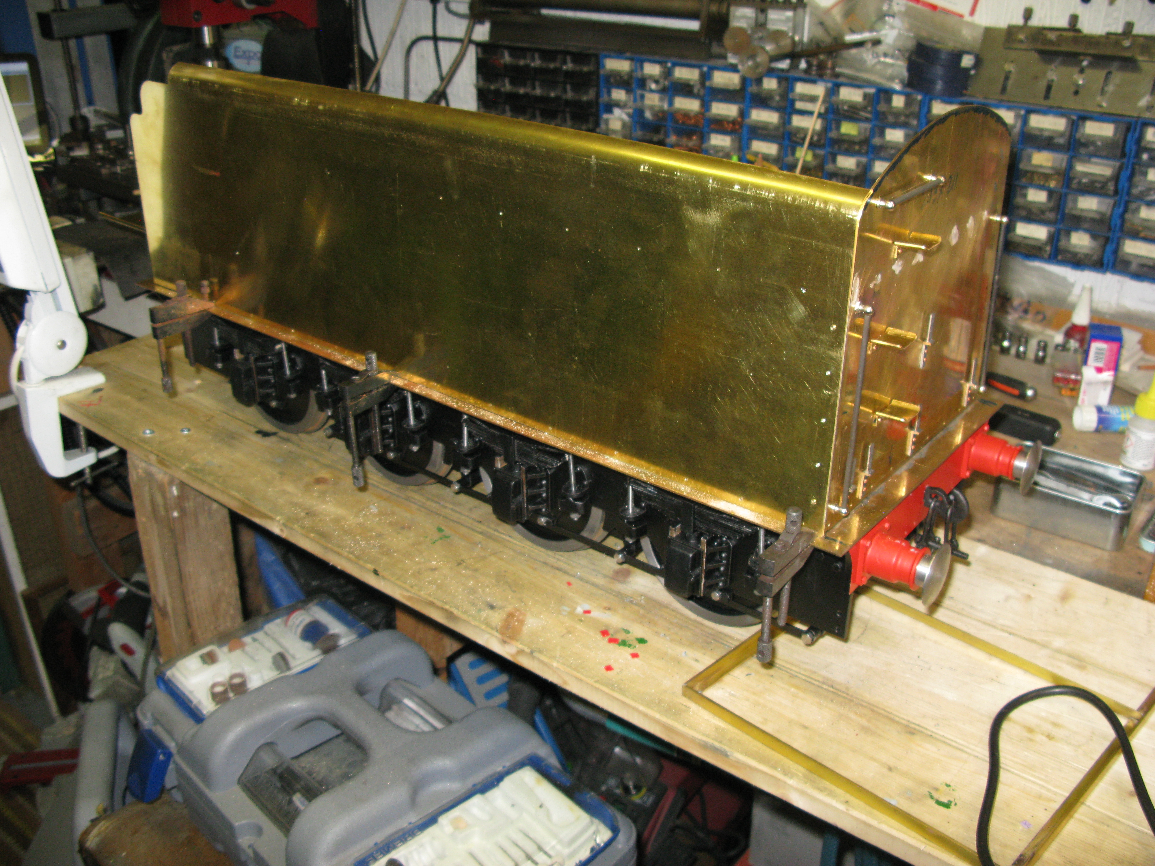
By way of explanation ……. the internal support angle attached to the sides is done in two chunks. The part shown above is obviously for the front section and another section is done for the rear which was in a photograph early on in the chapter.

All the rear support structure is now in place as can be seen above. The front now has to be done but this needs some design thought to allow for a removeable section when firing.
The as drawn front plate is drawn with a removeable section, however as drawn the section consists of the top vertical bit, the horizontal bit and the bottom vertical bit. I am not confident that having a removeable section that shape will sit nicely when put back in as the guides can only really be on the top vertical bit. The shape of the removeable bit mimics the shape of the tender coal floor with slopping sides. Another factor is the as drawn cut out comes quite low at the tender front and this means potential coal spillage. I eventually decided to only have the the top vetical bit removeable leaving the horizontal and lower vetical plate fixed.

The front plate is now in place and the support angle for the coal floor attached. Further back is the support bracket for the tender coal floor. The next bits will be the upper side plates to the front which will complete the shape to allow the tenderfloor sloping sides to fixed although the flat floor has to go in first.
before I do any of this though a quick leak test first on the progress so far.
But of course I cannot do the leak test with holes in the floor so I am making the feed water connections to the injectors and also putting in the Hand pump connection. These can then be blanked off with a simple cap.
The feedwater to the injectors is filtered and the design as drawn shows a soldered domed mesh but no mesh size. I picked up on an internet post from somewhere, I forget where, showing an industrial farming sprayer filter which will just slide onto a spigot so I obtained two of those in 50 mesh. This allows them to be taken off and cleaned if necessary. The resultant arrangement is shown below.
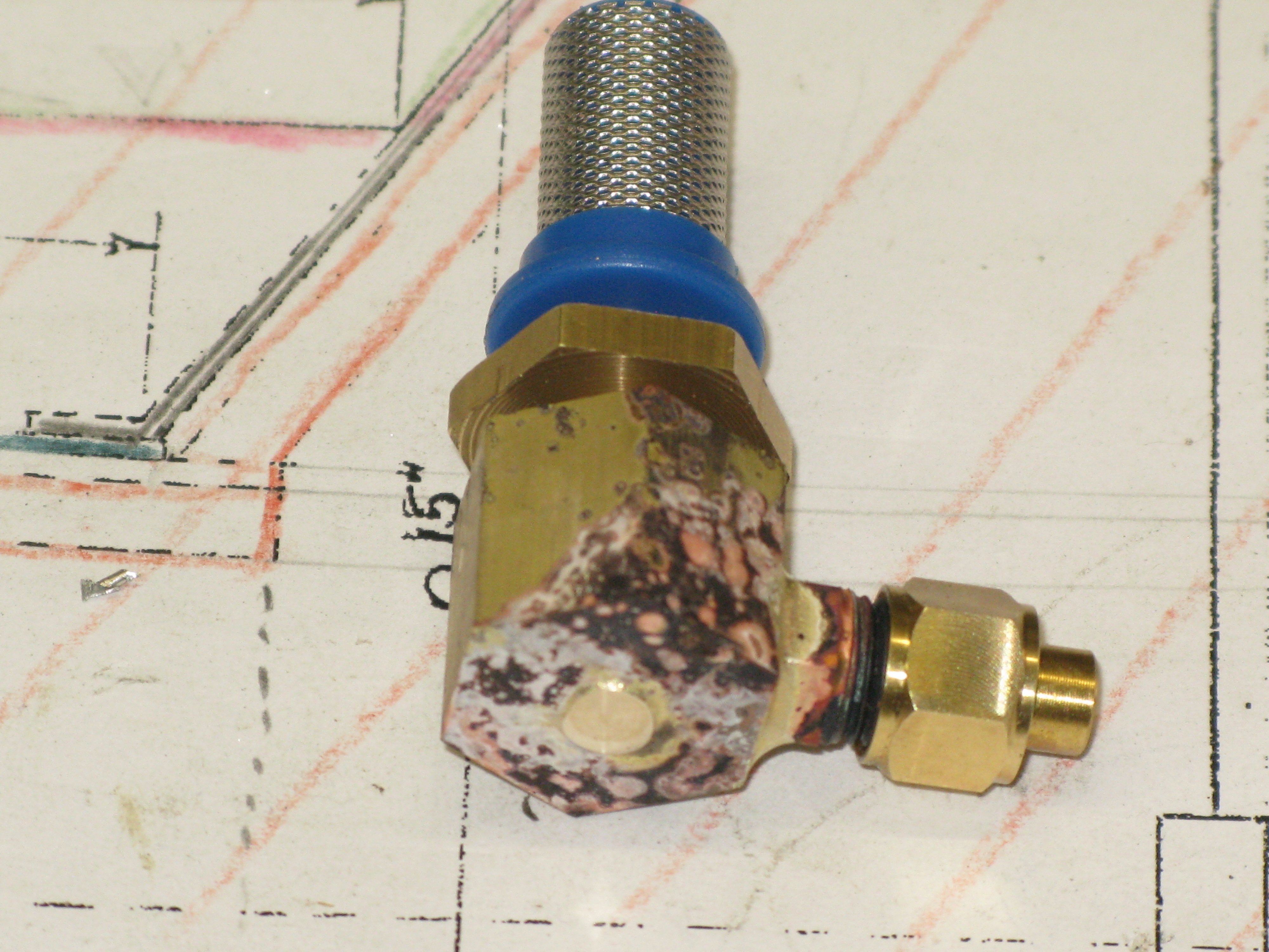
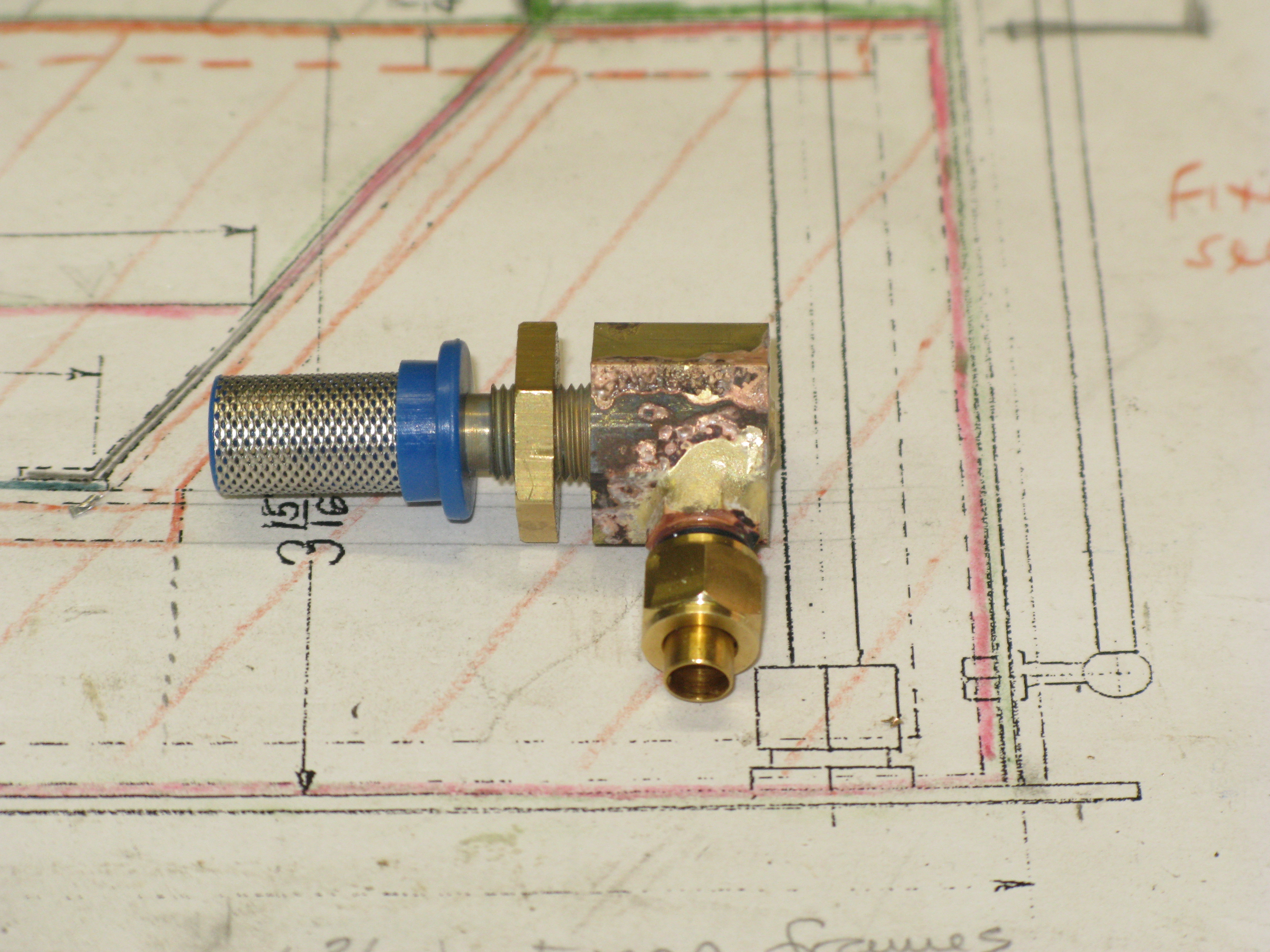
The photos were taken just after silver soldering with the filter pushed on just for the photo. I did have to open out the hole in the plastic base a little to maximise the bore. I also tried holding a filter underneath a running tap set so water came out of the filter but did not overflow and I judged the flow rate was as good as what comes out of an injector before it picks up. So I think 50 mesh is OK. If not it can be changed easily.
Whilst messing about with the above I also decided to put the front two upper plates in position. These were traced from the drawing and then the tracing paper put onto a piece of cardboard and offered up to the tender to check the fitting. It was Ok so the cardboard template was used to cut the brass. The two parts have now been soldered in place.

They have to have angle soldered onto the inside to support the coal bunker side plates.
Been under the weather recently with covid so not much done but all clear now.
I did a leak test on the tender by putting about an 1″ of water in the base and discovered one minor seepage spot on the join between sole plate and side. That was soon resoldered and the test repeated with satifactory results.
My next task is to put the base of the coal bunker in position followed by its sloping sides.
A question in my mind at the moment is should I paint the inside whilst I have easy access?
So after a sleep I have decided to paint the inside. First a coat of etch primer and then a coat of satin black.
Also another major decision ……. how to affix the coal bunker parts? solder or epoxy glue? I have chosen to use epoxy metal bonding glue for two reasons: firstly it allows the positioning to be adjusted easier and secondly it will take up any small gaps in the fitting process. Oh and a third reason, it does not require heat!

The inside painted and the bunker floor epoxied in place is pictured above. ( the paint is still wet)
Just visible in the top left is the small angle piece to support the sloping side at the top. This is epoxied in place. The sloping side has been made and bent so the side could be put in place to check the angle support was in the right place before the epoxy set. The right hand side will be done in a similar manner.
The sloping side was first made from cardboard and the template adjusted to give the correct fit. The template was then used to markout the brass sheet.

All coal bunker sides now fited.
However I have subsequently realised that I have assembled them back to front. In other words I should have put the back one in first followed by the sides and then the floor. That way the flanges would have been underneath and resulted in a cleaner looking finished job. It will not be seen of course as either the coal will hide the flanges or I will put a removeable wooden liner in to save the paintwork.
Moving on, the rear plate work top showed up a problem. It will not fit as the rounded top of the tender sides prevents the plate from sliding into place. It cannot slide into the tender as the front to back dimension is longer than the gap between the angle supports on which it rests.

The only solution was to fit in two halves. This gives me a solution as to how to service the hand pump if need be as I can make one half of the plate removeable.
But then a sleep and I realise that the waterscoop and back of the coal bunker go right across the join so no removeable bit.
With the two halves in place it is possible to get at the four nuts that fix the water hand pump to the tender floor. The pipe connection is also possible but more difficult.
A leak test on the coal bunker with the tender full of water showed up couple of weeps which were cured with epoxy resin which when runny wicks into any gaps. A retest showed all was well.
Having got the two halves of the back plate fitted I could make and fit the coal bunker rear plate. This was straight forward but I was not confident on soldering across its length and up the sides so I decided to just spot solder at the side tops and a couple of spots on its base.
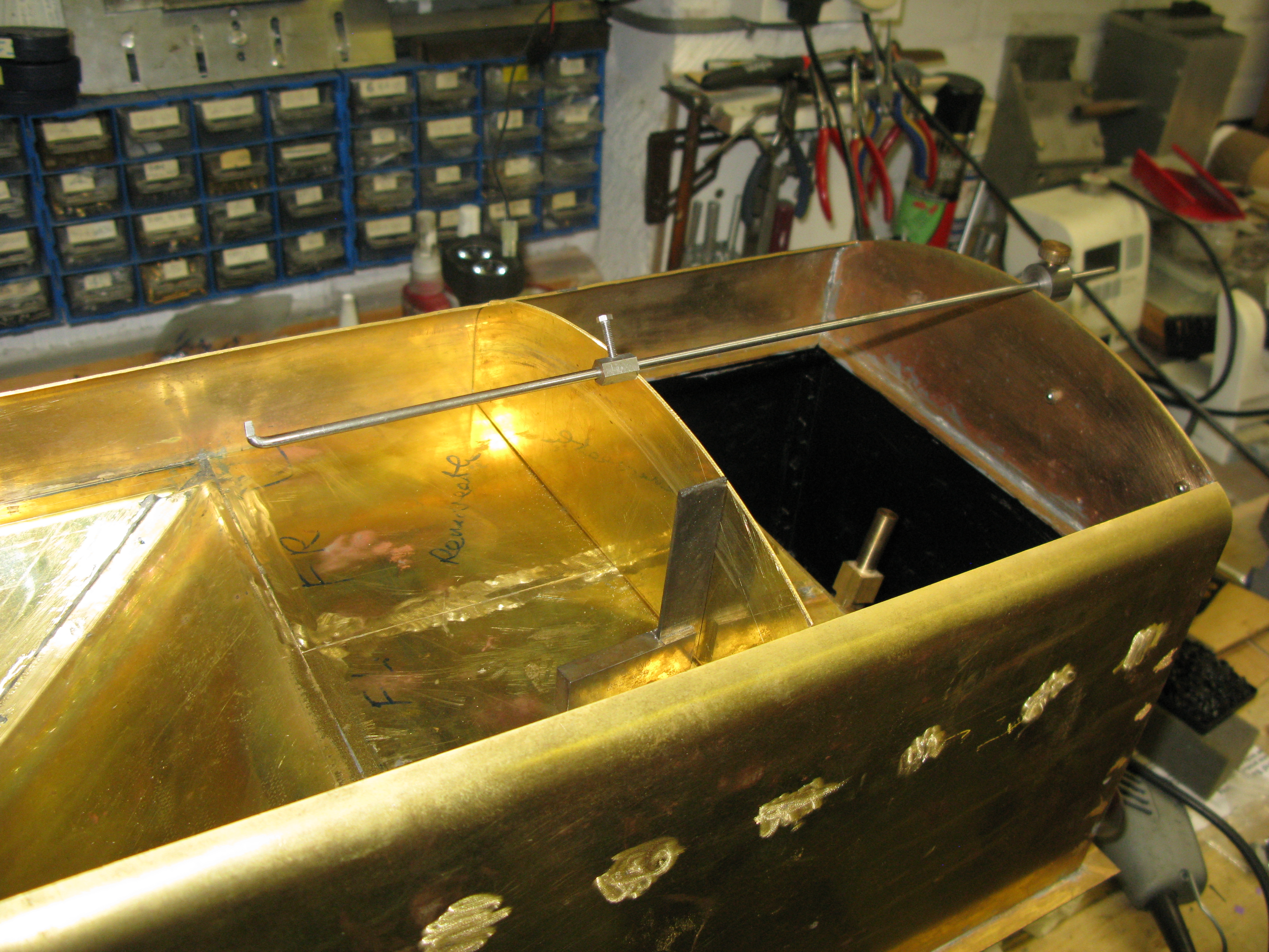
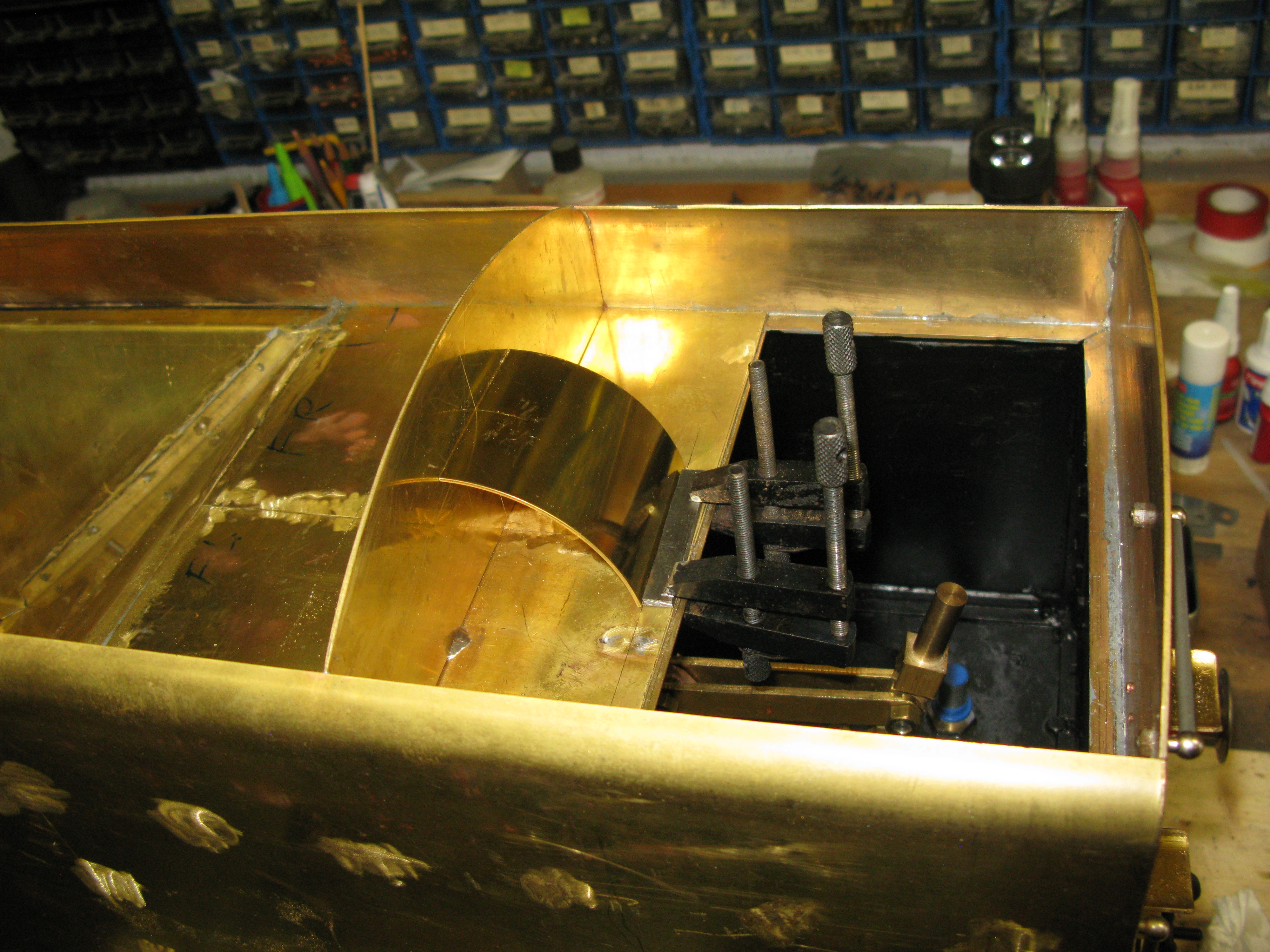
In order to keep it square whilst doing this soldering is used a small try square and a gap gauge as shown above.
With this in position I then started on the dummy water chute. The drawing gives no width measurement for the chute but fortunately I could just use the dimension from my A4, being 2 1/4″. A stip of brass that wide was rolled to the 1 7/8″ radius and then cut to give a quarter segment. This was then soldered in place using a temporary stop to prevent it slipping.
With the top sildered the temporary stop was removed and the bottom soldered. The process was repeated for the other side.

The sides to the chute were then cut and soldered in place.

My attention now turned to making the removeable front plate of the coal bunker. The shape was first established by paper former which was then glued to the brass sheet. The cutting out was left deliberately oversize to enable the exact fit to be subsequently obtained. The fitting process of trial and error, on and off, eventually produced a fit that I was satisfied with.
This removeable piece has to have a pair of slides into which can fit. I made these by soldering on two pieces of 20 gauge brass strips to form a U into which the plate could slide. These small brass strips were soldered in place using solder paste and a resistance soldering unit which can very precisely heat up a local area.

The slides only fit at the top of the plate and this is sufficiently robust to hold the plate firmly.

The last bit to make on the structure is the removeable plate at the rear of the tender for access to the hand pump and easy water filling. The plate has to be shorter than the width of the tender in order for it to slide in position past the curved tender side.
This plate has the trender filling standpipe fitted which is 1 7/8″ diameter. Fortunately I had an odd piece of copper tube of that dimension. The plate had the hole for it trepanned in the mill and then the tube soldered in position.

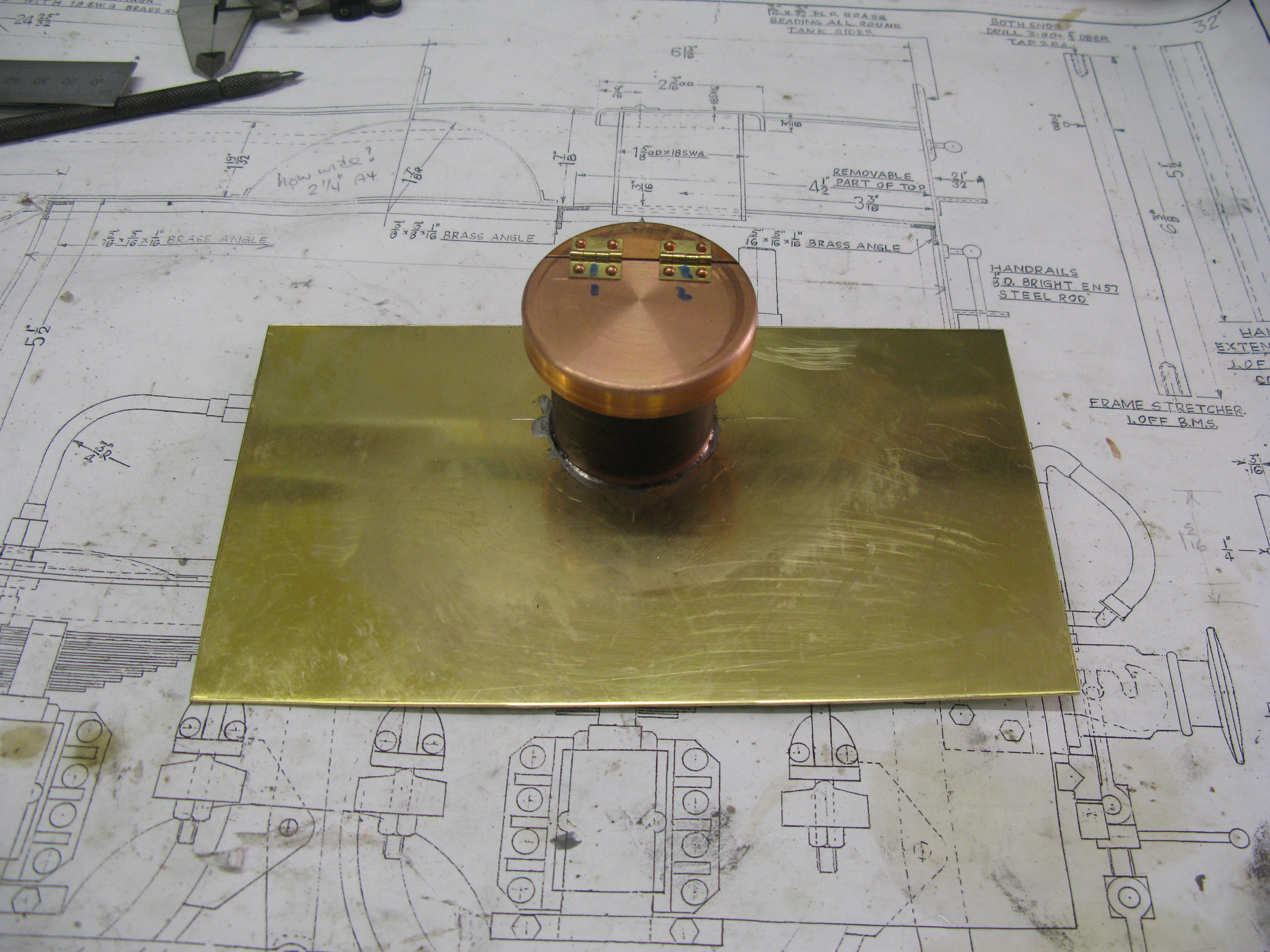
The lid to the standpipe is 2 3/16″ diameter and is hinged by splitting the lid and fitting two hinge points. Searching the workshop I found a 2 1/2″ copper bar ( yes I was surprised too) when looking for a steel billet so I cut a bit off that and turned that to make the lid.
Turning the lid. A spacer behind the stock material to ensure it is square in the chuck.
Slitting the lid was done in the mill with a 1/32″ slitting saw.

Hinges were riveted in place and then the lid was soldered onto the pipe.
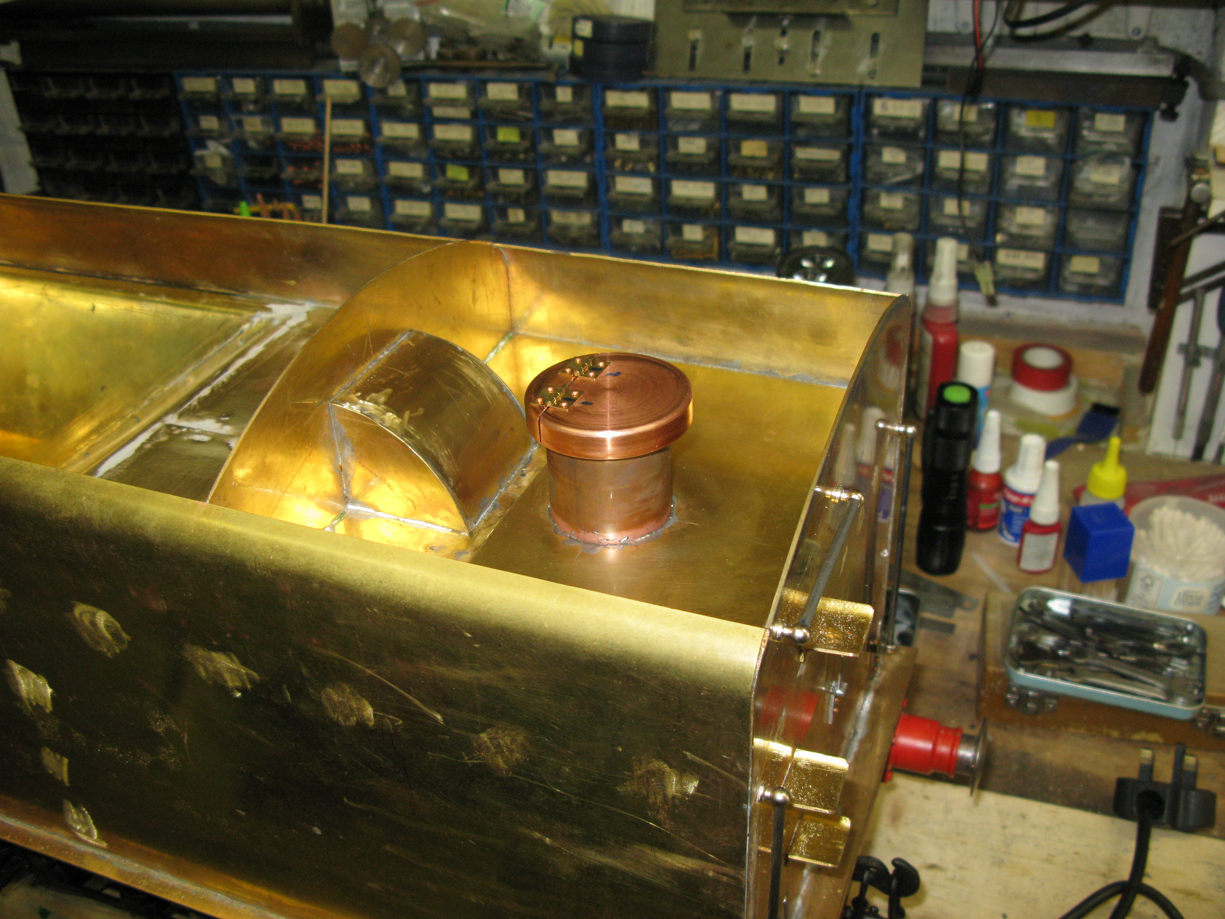
The completed rear plate.
Now onto fitting the beading. This is 3/16″ x 3/32″. There are two lengths along the sides one at the start of the bend and one on the edge. I mulled over the various ways of going about fixing the beading and eventually decided upon screwing it on and with an epoxy glue. This avoids any heating which I feared might result in a joint giving up.
The beading was first drilled at 3″ intervals for 10 BA tapping and then it was clamped in place to jig drill the tapping hole in the tender side. To ensure the beading was level I used a hight gauge as I worked along the length.

Each hole was drilled and tapped one at a time being screwed in place and then the clamp moved to the next one.
The top beading was easier as it just had to follow the edge.

The plan is to skacken off the screws and fill in behind with the epoxy glue and then tighten it all up again.
When it comes to the tight radius bends at the front (and eventually the bend on the rear and front plates) I turned up a circular beading using a form tool.

When parted off this forms a nice piece of beading from which to cut 1/4 sections to form the radius bends.
The beading is usually bought and supplied coiled so get straight lengths the coil bend needs to be removed. I have this little device for straightening the bend. It was built many years ago for putting in bends but it equally serves for taking them out.
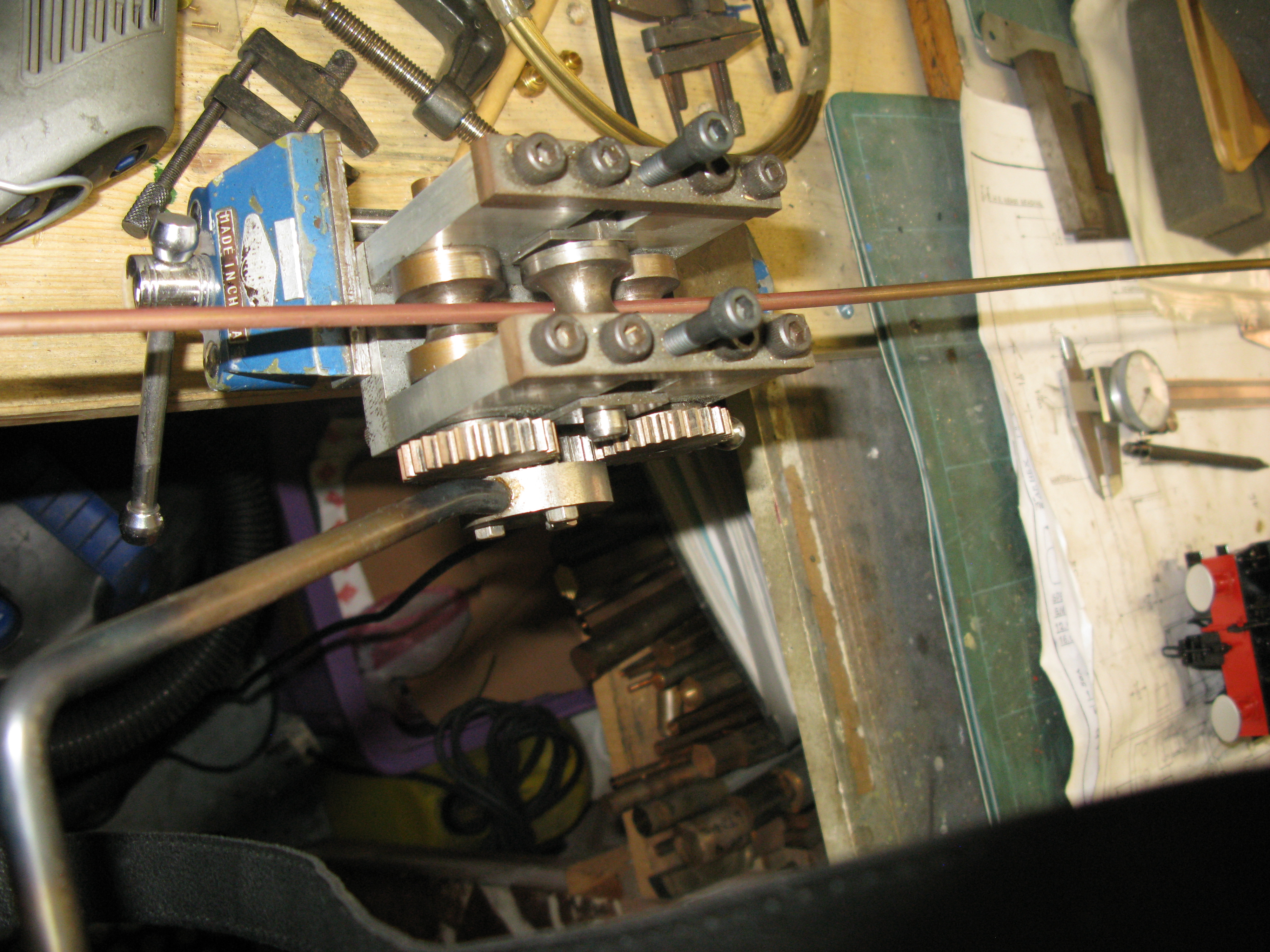
The other difficult bending process is putting in the curve on edge and to do this I use an add on to my home built rollers which are formers in the shap of the beading.

These are able to put a nice curve into the beading without other deformation taking place.

machined curved beading in place

Nearly there!
The observent readers may notice that the removeable front plate now has guides along the full length of the sides which is different from the description given much earlier in the chapter. The reason I have done this is because I did not like looking at the gaps! Small as they were it did not look to me to be right so I extended the guides and also put a small eangle on the bottom to seal that gap too. I may later put on the false bunker door that exists on that plate.
The tender structure is now all but finished. There is a false floor in the front to bring the height up to the same level as the cab but to do this I need to get the injector valves made and fitted and the manual brake stand done as the floor will have to slide over these into position.
The injector water valves are fabricated to have the water inlet coming in from the side. There is not much room for them to be mounted in the as drawn position close to the tender frame. The valve itself is made from 1/2″ AF brass turned down at one end to 1/4″ to accept the hose connection and threaded 3/8″ x 32 at the other to fix to the floor. The bore is a No. 13 drill then opened out to 3/16″ to form the valve face and finally tapped 7/32″ x 40 ME for the valve stem to screw in.

Injector water valve body fitted.
Although not shwon on the drawings the full size tender had steps where the injector valve has been positioned so it is not really practical to fit these but I might have a go when I can see how the hose connection naturally runs onto the loco.
The water valve is made from stainless 7/32″ dia. Its simple, tyurned down at the valve end to have an angled seating profile and threaded above that. The handle is a 3/32″ dia rod with a right angle bend silver soldered into the top via a 3/32″ hole.

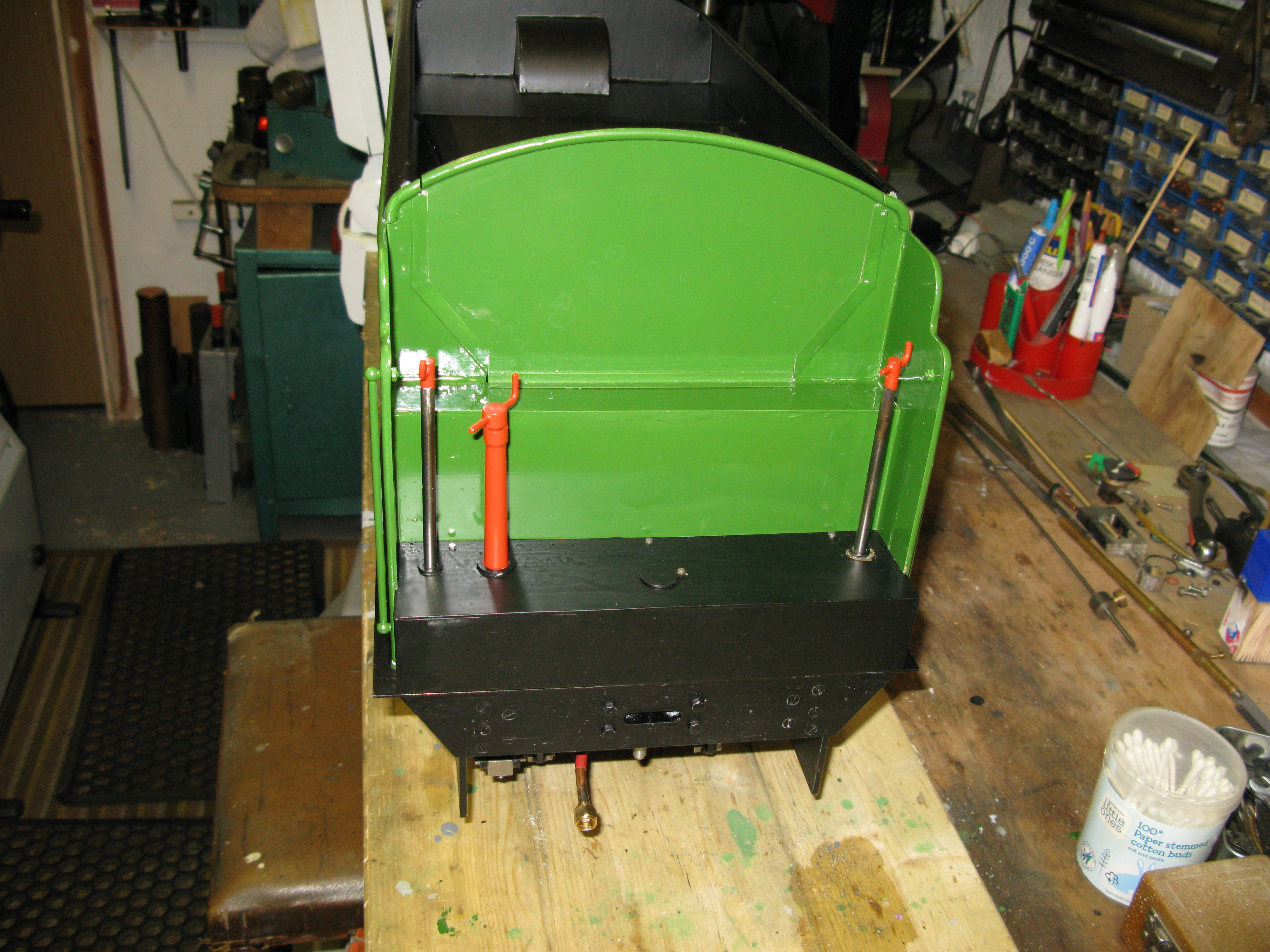
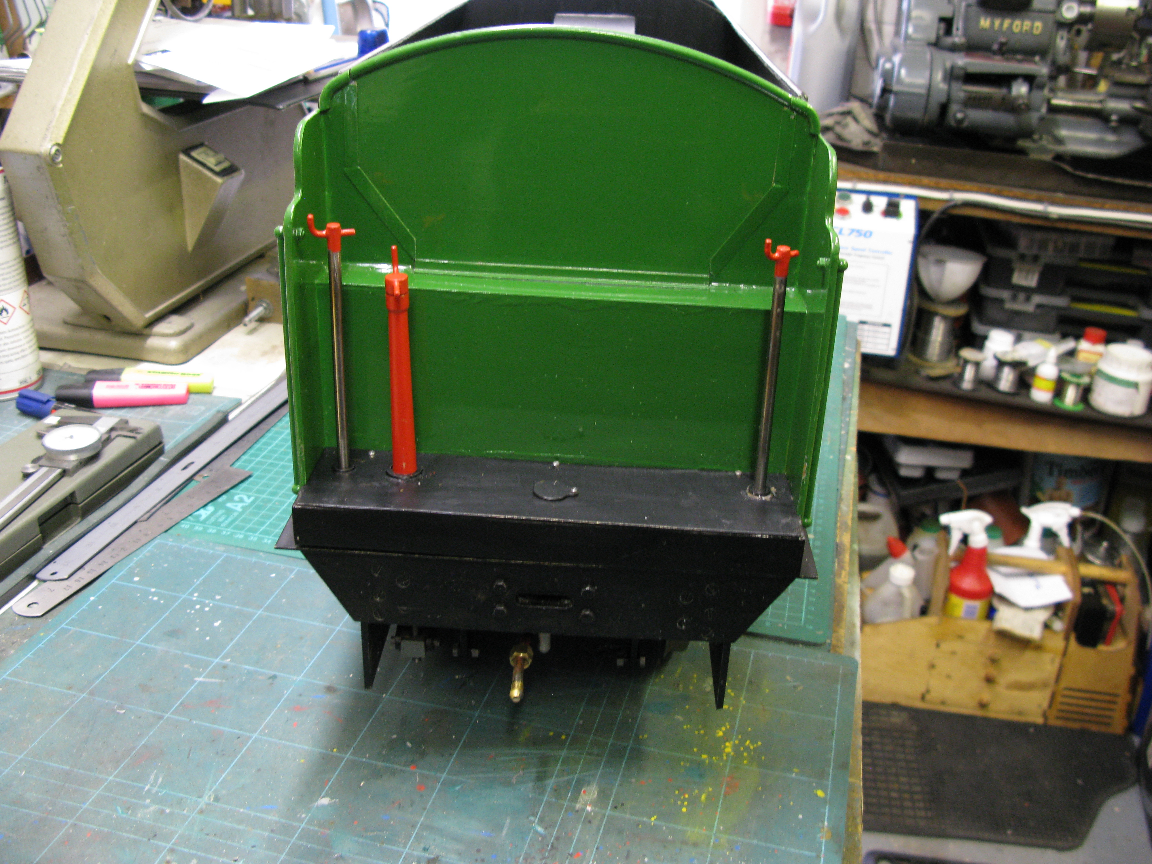
The two injector water feed handles fitted.
The hand brake staubchion is next. This requires a taper to be turned. First I drilled the 7/32″ hole through the brass stock bar with a long series drill and turned one end down to the staunchion top diameter and rough turned the length.

This enable the bar to be set up between centres to machine the taper. To get the taper I use the four jaw chuck in the tail stock and set over a square centre using the independent jaws having first ensured the two horizontal jaws are parallel with the lathe bed.

In this case the set was only 1/16″ to achieve the required taper, however the set up had one problem which was the saddle travel was insufficient to do the whole length of the taper so it had to be done in two bites.
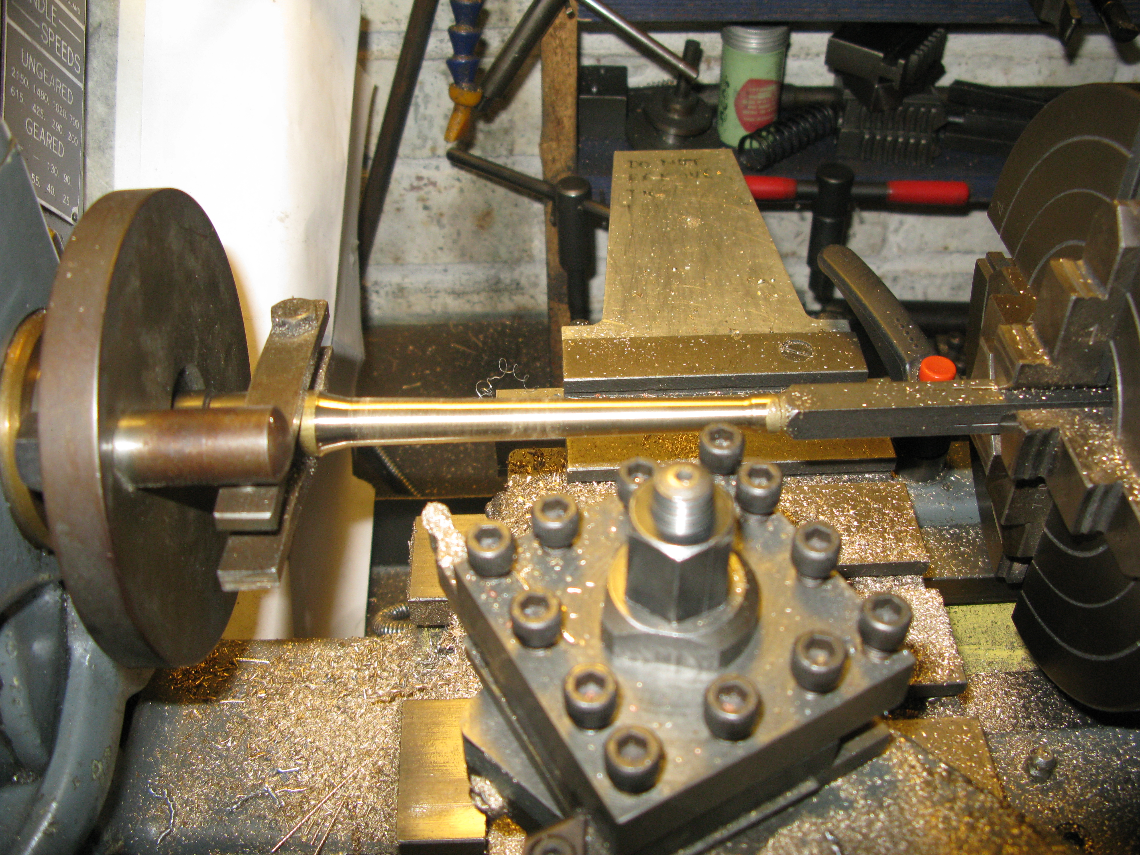
The finished taper turned staunchion was then mounted in the three jaw chuck using the 7/32″ drill to ensure it was gripped true and the bottom turned to give a 7/16″ x 32 thread for bolting to the tender.

The brake staunchion in place.
The brake handle is a simple affair being a length of 3/16 rod with a 2 BA thread at one end to fit into the brake operating lever and at the handle end it has a 3/8″ dia. boss silver soldered on with a 3/32″ bent rod to make the handle similar in style to the water valve handle.
There is nothing to prevent the handle unscrewing upwards so I might just fit a collar underneath held in place with a grub screw.
With all the operating handles in place I can now make the fale floor to match the height of the cab floor. It has to be 1 1/2″ high above the tender floor. I have made it from brass sheet and to hold it in place a piec of 5/16″ brass angle is epoxy glued to the tender front coal bunker wall.
To hold it place whilst the glue set I used temporary upstands against which two pieces of balsa wood were placed.
The floor is just an L shaped form with a 5/16″ brass angle to form the base at the front inside. To get a square edge to the floor the front and top were soldered together rather than bent. The sides are closed off with a soldered piece so the tender side is flush. The floor is held in place by three 10 BA HH headed screws into the angle at the back.
The holes for the two water valve handles and the brake staunchion were capped with a small upstand to give a close but free fit around their content.
The central hole in the false floor is for access to the drawbar pin. This is a 1/4″ dia pin with a 3/8″ boss at its head which when inserted fits through the tender floor. To put in in and get it out it was made with a 4 BA theaded hole into which a insertion/removal tool screws.
The hole will have a swival cap fitted so once the pin is in place the hole can be covered.
The last job on the tender is to fit the pipes underneath. The two water pipes for the injectors are straight runs of 3/16″ copper pipe into thier repective valves and feed connections.
The pipe from the hand pump is free at the front end to allow connection to the loco to be managed. The pipe I had was not quite long enough to put in the usual coil to gain the flexibility required so I put in a few bends to provid the same result albeit a bit stiffer.

Water feed pipe runs being installed.
With the water feed pipes in place the underside of the sole plate on the outside of the chassis can be etch primed and painted black. Then to turn the tender over and etch prime all the top.
Not much happening on top but a lot of paddling beneath the water line. Painting is a long job.

The sole plate and false floor have now all been done in semi matt black and the rest is in grey etch primer. This will be folllowed by undercoat. The length of side above the bottom beading will also be done in the same black. However this will end up with a shine from the final varnish coat.

First side with an undercoat brush applied. Not visible is some masking on top of the sole plate and above the bottom bead.
With the undercoating done the first top coat of Darlington Green was applied by brush. Two coats were needed to cover the undercoat successfully. The final two coats were applied by airbrush spray gun.

Masked up and spray coat being applied to the side.
The final spray coat gives a high gloss and in the photo above can be seen reflections, they are not marks!
Painting is a long job as each coat has 24 hours inbetween coats.

First transfer added
To mark out the transfer positions I use aircraft trim tape (It comes in a varietu of widths). This allows me to precisly locate the transfer.

One side fully lined out.
The white lines at the top and bottom of the side were done with a lining pen which does not produce the chrisp lines as those on the transfers. (probably a lack of skill!).
Once the fully lined out side is well and truly dried out a coat of clear varnish will be applied.
Both sides are now done and varnished and I debated wheter or noy to put lining on the rear. The full size does have the lining on the rear but I was concerned about getting the transfers on successfully over the lamp brackets and between the grab rails and steps. Finally I decided to pluck up the courage and do it.
To get a better working position for applying the transfers and doing the top and bottom lines I tipped the tender on end and held it in place securely.

The cord is to endure it does not topple away from the bench but the main clamp holding it steady is the piece of wood clamped to the bench and to the brake rods. it was suprisingly rigid, probably helped by its weight.
So after a few days putting on transfers and waiting for them to dry before adding more transferrs the tender is fully lined out. The rear turned out reasonably well in the end.
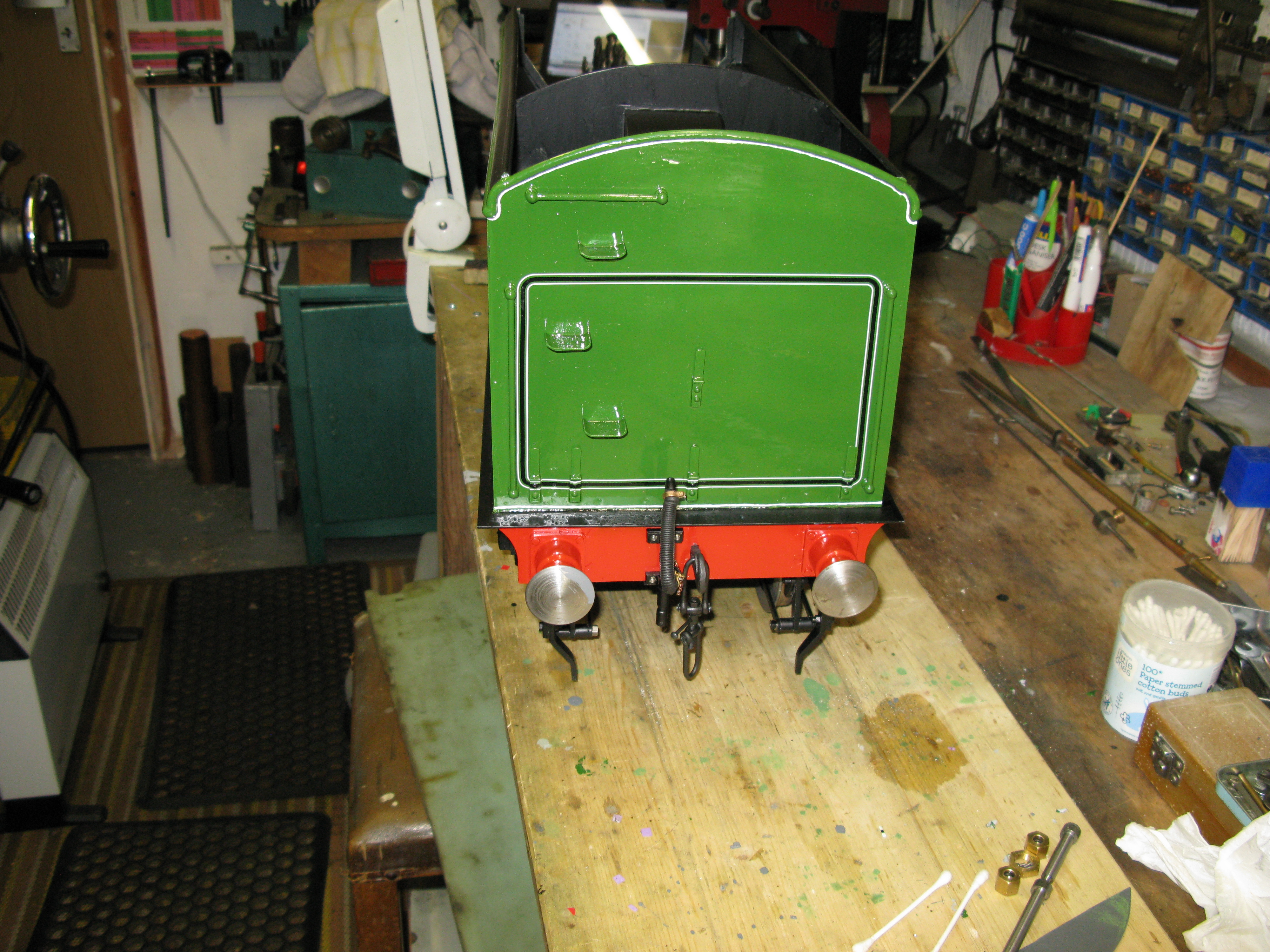
In the photo above the rear vacuum brake hose has been made and fitted.

a finished view from the rear.
… and a finished view from the front.
I now have to make the protective insert for the coal bunker.
Well actually I have to put right a booboo. I had started to make the fall plate that spans the gap between the loco and tender. and in measuring up for the size I discovered I had made the tender false floor too high……….bu****r. So now I have to see if I can cut it down to size by about 5/8″. No idea how I managed to make the mistake. The bigger remedial job will be to relocate the angle that supports the false floor as this is soldered to the front plate.
The new level of the false floor can be easily seen by comparing this photo and the one above.
Although not strictly to do with the tender the photo below showa the changed livery on the boiler bands and the lifting gear needed to get the loco up onto and down from the bench.


I think that brings me to the end of the construction work.
Now I can focus on getting it boiler tested and seeing if it will run under its own steam……..
As a sort of PS I mentioned that the tender coal bunker would have a liner. Well I have made the liner base which is shown below. It is three ply wood.
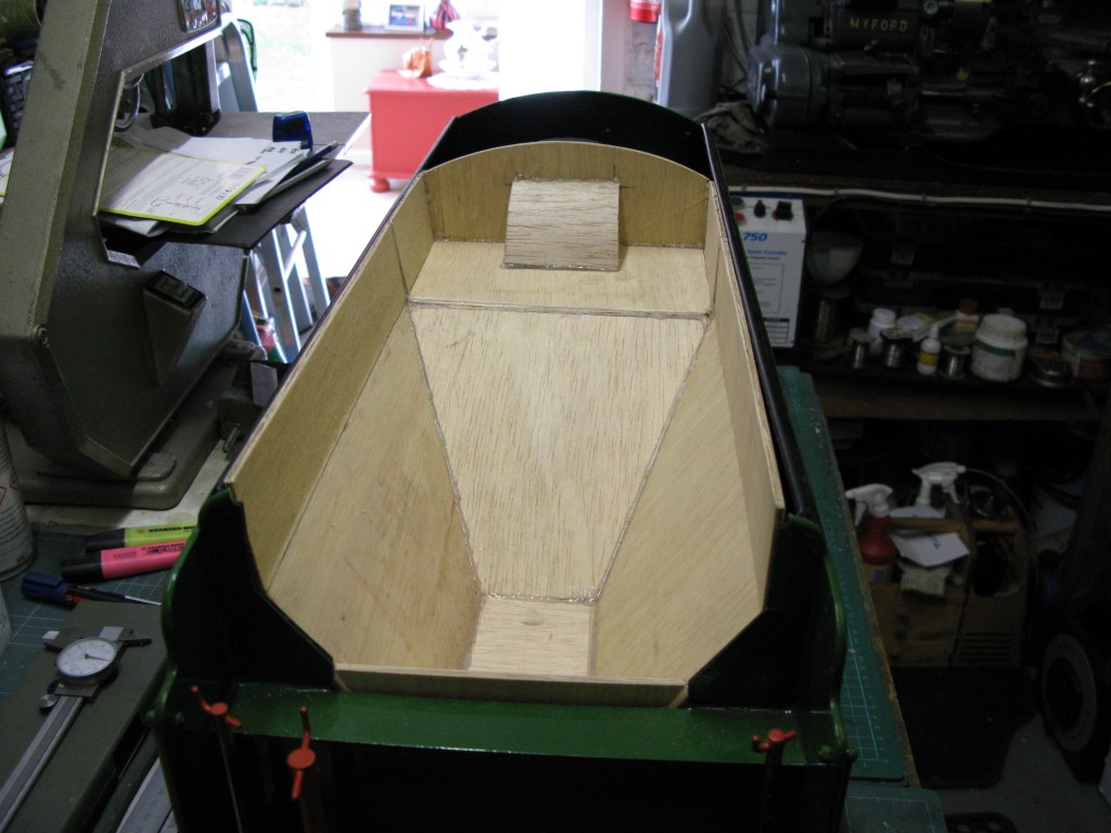
The liner will have a fibreglass coating and then be painted black.
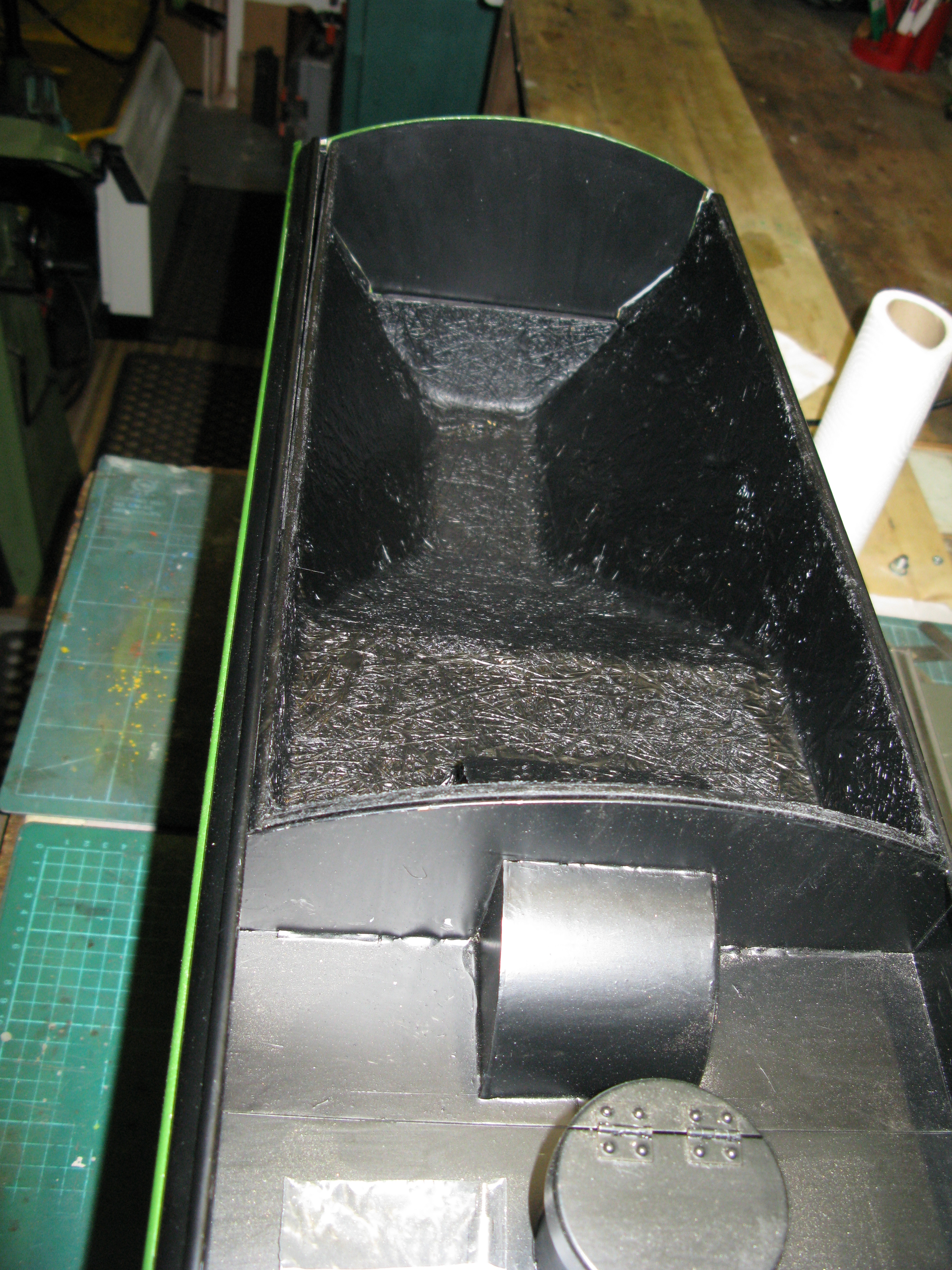
The finished liner inserted.
