You may wonder why do the axle boxes now. Well my plan is to use the two plain axles to help align the tender frames to be square when fitting the drag beam and buffer beam.
The axle boxes I chose to make are the plain type. However the plain type axle box is dimensioned to be shorter than the split type as it has no pins that hold the removeable part of the axle box. The drawing shows the plain type only for the coil spring variant of the springing that has two spring retaining pins fitted to the axle box. As I am using live springs I only need a single spring hanger pin in the centre. With the shorter axle box and the bore for the axle the amount of material left to screw in the spring hanger is only 1/4″ max so I decided to increase the height of the axle box as much as I could within the restraints of the material supplied to make them.
The axle box material is cast iron supplied as one stick from which all six are made. Measuring its length I calculated I could get an axle box height of 1 7/16″ plus from the stick rather than the 1 3/8″ as drawn.
The first task is to mill the stick to get a flat face from which to work. The stick is trapezium shaped and as the main machining to make the axle box would require the wider face to be flat so as to bolt to the machine table this was machined first. The stick was thus bolted down to the mill table as parallel to the table as the rough casting could be set and the top machined flat. Some moving around of the bolting down fixings is required to machine the whole surface. The sides were aslo machined at this time to give the dimensioned width as this ensured they were square with the top finish just milled.
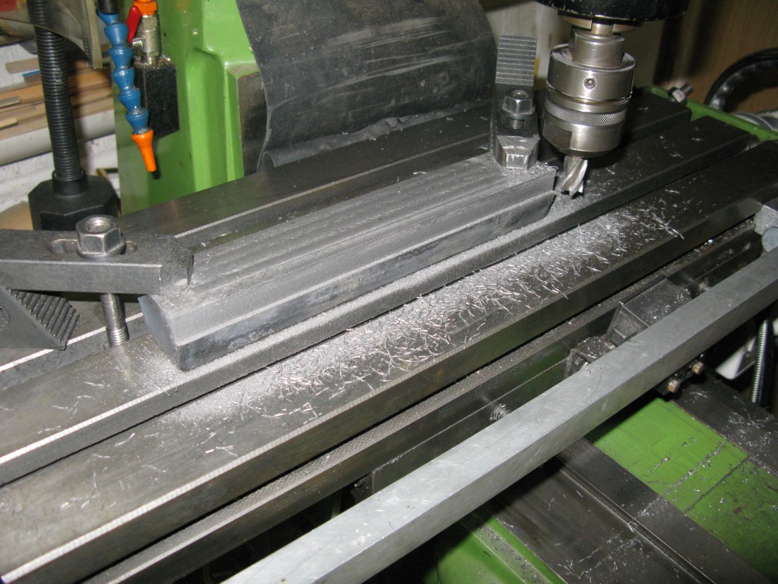
The stick was turned over and set against a fence to ensure it was parallel with the table and the axle box inner sides machined to 1 1 /4″ to fit the horn blocks. The flange depth for 1/8″ frames being 9/64″. Finally the top was machined to give a depth of 1″.
The stick was then split into the six axle boxes using the band saw. A check that they all fitted the axle boxes without shake found them all OK.
As the band saw does not give a perfect square cut, each axle box was put on the lathe in a four jaw chuck to square the ends. This process maximised the height of the axle boxes to 1.45″ as this was the largest I could get from the cut sections bearing in mind the two boxes cut from the end of the stick have a taper from the the way the cast stick is made.
Before doing any more on the axle boxes I decided to make and fit the keeps.
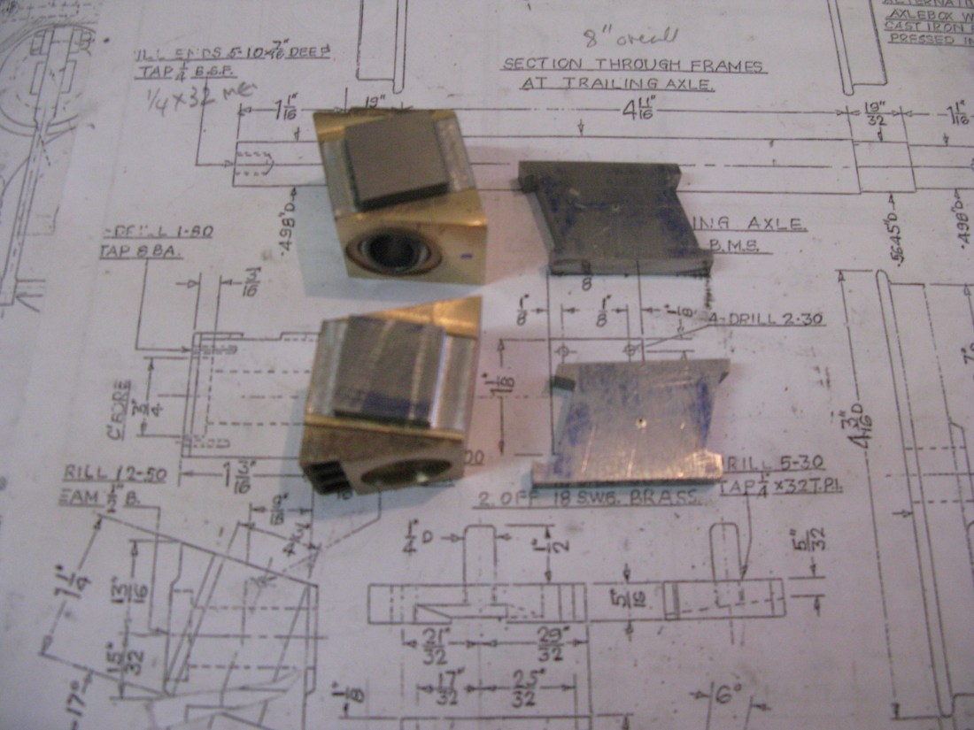
The keeps as drawn do not show one for the live spring version and this has an affect on the holes to be drilled. The live steam version of the keep only requires a single hole for the spring support pin to pass through not the two holes as shown for other versions. The spring pin is 1/4″ diameter so a 9/32″ hole is suitable. Looking at the spring hanger dimensions the centre line of the spring in relation to the frames can be established. This worked out at 5/16″ from the front edge of the frame and hence the front edge of the keep.
To make the keeps I first rough cut to length some 3/16″ x 1″ flat bar and then in a pack of six machined the width down to the required dimension by machining both sides to remove the natural curved edge of the bar. The machining was done against a fence on the mill table for ease of set up. the ends were then machined square to give the length of 2 5/16″.
Using the fence set up again each keep had the 1/32″ step machined at each end.
The keeps were then put into a pack of six again against the fence and the two 3/16″ holes for fixing to the horn block drilled. Finally each individual keep had the 9/32″ hole drilled by using two fences at right angles so the each keep was automatically aligned in the correct place for drilling.
With the keeps complete each keep was placed on its horn block and the horn block jig drilled No26 for tapping 2 BA. The tapped holes were 1/4″ deep so as not to break through the casting.

The choice of boring the axle boxes and then make the axles to fit or make the axles and bore the horn blocks to fit is a matter of prference. I chose to make the middle and rear axle and then bore the axle boxes to fit. The reason for this is that turning an axle to have the same diameter over its full length is achievable only if the lathe has no wear and is accurately set up. My lathe (Myford Super 7) is now 60 years old and whilst in good condition turning over 5″ with no taper is, well challenging. Bear in mind that a thou difference is over half the axle/axle box tolerance for a good running fit. The axle making is in another chapter together with the crank axle.
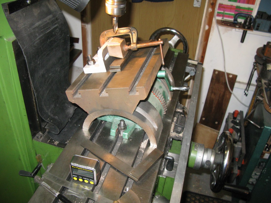
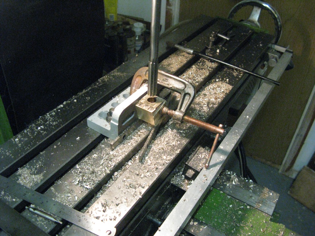
The axle boxes were first set up on the mill table and clamped down against a fence square. I used a parallel against the fence to get the axle box to sit centrally over the mill table slot so the drill would not damage the table. The axle box was centred under the quill using an edge finder to locate the edges and then the end was located and moved to 5/8″ to locate the centre of the axle. A centre drill was then used to spot the hole and a hole drilled to 5/16″.
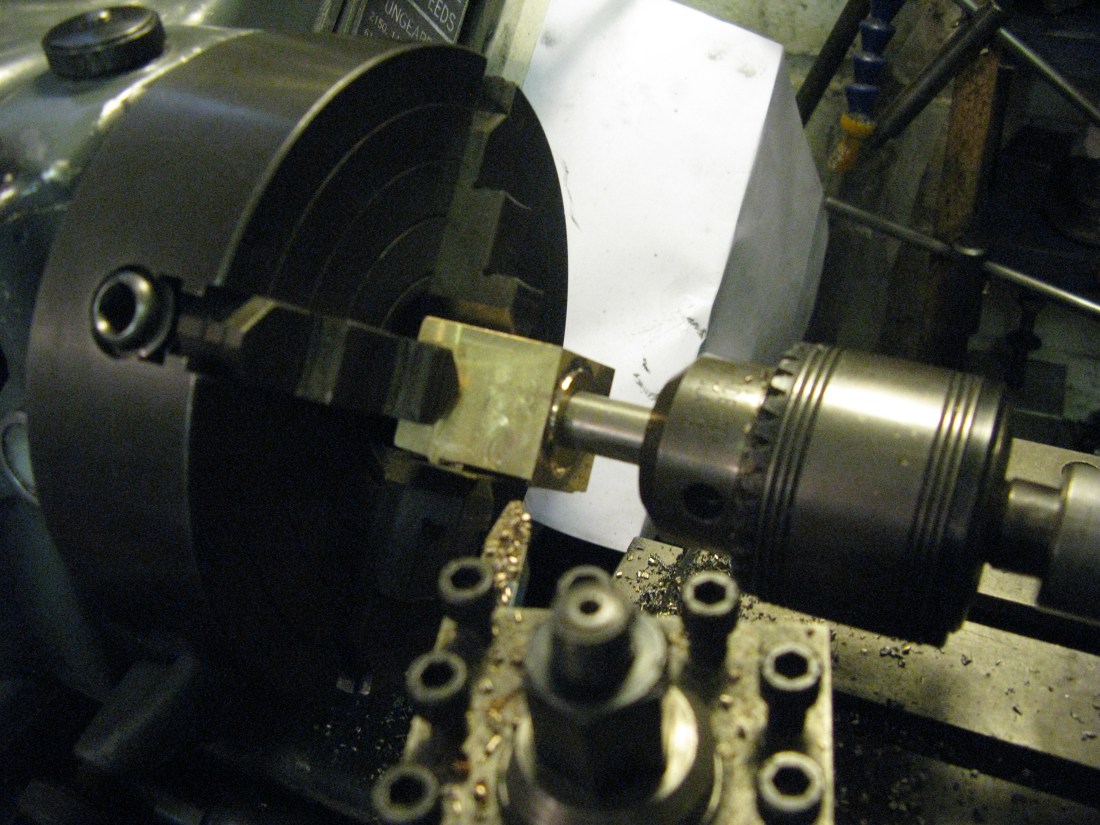
The axle box was then put into the 4 jaw chuck and using the hole and DTI it was centralised in the lathe. The hole was then drill open to 1/2″ and then bored to fit the axle end, the axle end and axle box being temporarily marked to pair up. With all four axle boxes bored the axles and axle boxes were trial fitted into their horn blocks to ensure all were square and axles rotated freely. They did.
The oil hole in the axle box was spotted through the hornblock by a transfer punch and drilled 1/16″ and counterbored 1/8″ for 1/4″. The hole to be tapped 1/4″BSF in the base of the axlebox for the spring hanger was spotted through the keep with a transfer punch, drilled and tapped to a depth short of breaking through into the axle bearing surface.
The two axle boxes for the crank axle were bored later after the crank axle was made. The process was intended to be the same as the other four but when machining the bore on the first axle box for the crank I inadvertantly machined it 8 thou over size so the axle was a sloppy fit. Here comes the asterisks and other unintelligble signs denoting the swear words! To overcome this aberration I chose to bush both the axle boxes with a phosor bronze bush and so the bore was opened out to 29/32″ to give a reasonable bush wall thickness whislt not taking too much metal away from the axle box where the spring hanger is to be screwed in. The oil hole and spring hanger hole were added as on the other axle boxes.
Cartazzi axle boxes
These are a gun metal castings and the first step is to machine the faces that slide in the horn blocks. A block was initially held in the vice and the face that abuts the dummy cooling slots cleaned up. The reason for doing this first is that the web of the dummy cooling duct is thin and most of the material to be machined away would thus come from the opposite face.
The block was then clamped down onto the mill table against a fence with a side clamp and a top clamp halfway across the top surface. The reason for this set up was that it would produce a parallel face to the one machined in the vice.

Having measured the gap between the horn blocks accurately the block was machined down to size, a second clamp put on the surface just machined, the first removed and the other half machined down to match.
Then followed a check to see if the axle box would fit the hornblocks. It was tight. So a process of gentle filing (more scrapeing than filing) and bluing to find the high spots followed until the axle box would slide easily up and down the horn blocks.
The second axle box followed the same pattern.
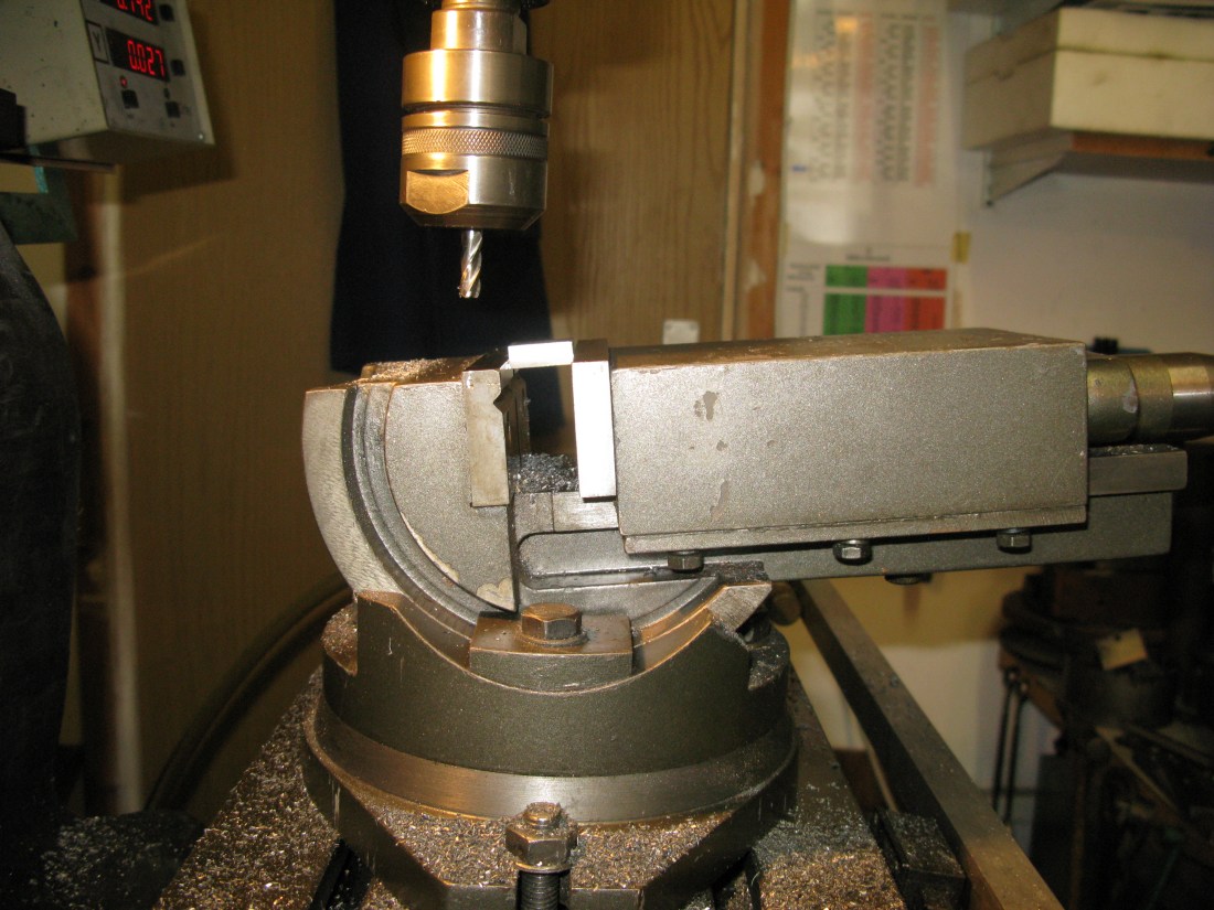
The next faces to be machined were those at an angle of 17 degrees i.e the front and back faces. To do this I used an angle table and angle bracket to which the block was clamped.
The packing underneath is to raise the block above the top of the angle plate and clear the cutter.
The last two faces are the bottom and top. The block was clamped to a fence on the mill table and set square vertically and the bottom cleaned up. The block was then turned over to do the top face which is raised 1/16″ above the duct slots. I had to have a couple of stabs at this as I had not taken enough off the bottom face which would have left the top face too low. It was a simple matter to turn the block over take a bit more off and then return to the top face to finish to height.

Next the slot in which the sliding pad fits. A straight forward job with a slot drill 1/16″ deep.
Now the holes for the axle. The block was mounted against an angle barcket and placed upon parallels to clear the mill table. The two edges were found from which the centre line of the hole was determined. A stab with a centre drill followed by a pilot drill and then a jobbers drill 1/64″ under 1/2″. This was then reamed to 1/2″. To finish off the hole was counterbored 3/4″ by 5/32″ deep to hold the retaining screw head that keeps the exle box from coming off the axle.

The inside face of the axle box is turned down to give a 1/16″ high shoulder around the axle, this was achieved using a 4-jaw chuck with only two jaws on the parallel faces to the bore with a 1/2″ bar in the tailstock for support. Light cuts with a round nose tool resulted in a suitable finished shoulder.
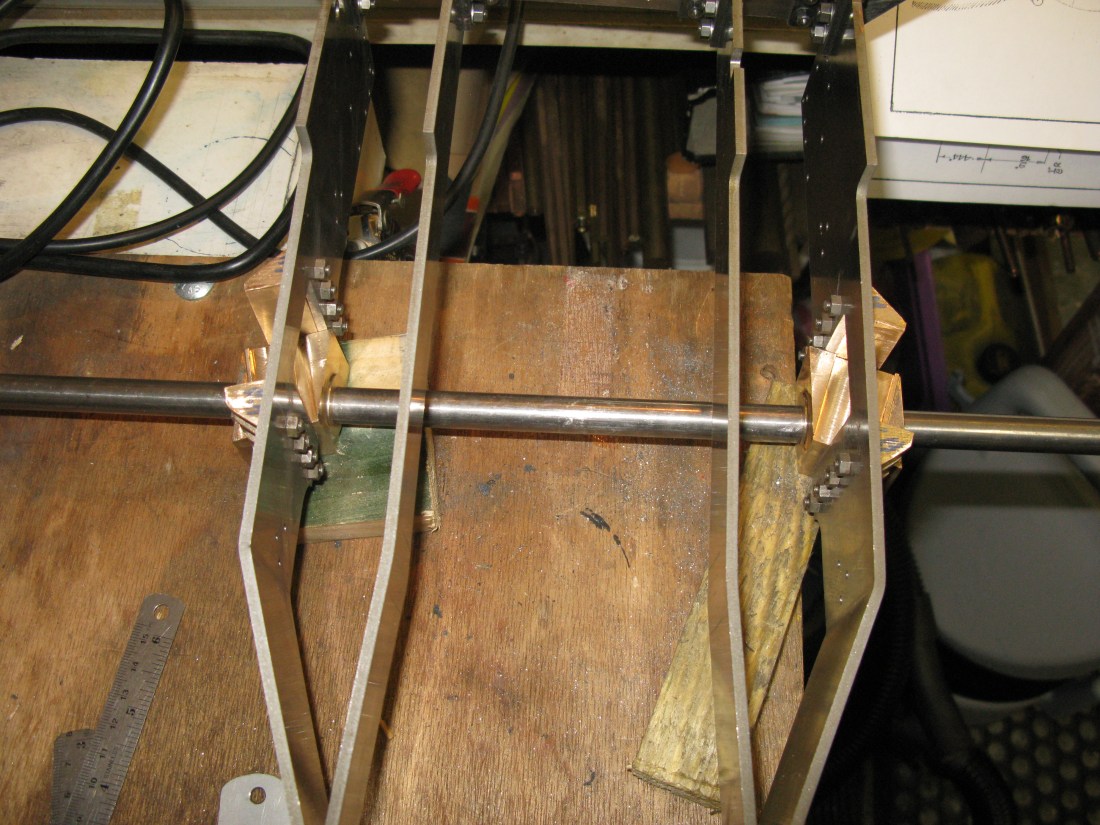
With both axle boxes complete to this stage the temptation was too strong to resist a check in the horns to see if they lined up. A long 1/2″ bar to act as an axle and lo and behold …….they didn’t! The bar would not go right through one axle box without jamming. The cartazzie axle arrangement is not the easiest to handle at this stage with two loose axle boxes and a bar and I fiddled around for a long time before being convinced that the problem was at least one angle being out but which one? It could be the 17 degree horn blocks or the 17 degree axle box or the bore. As I had previously expressed doubts over the digital angle gauge usage I decided it was not the bore which was at right angles to the face and that was determined by the mill table and quill. So it had to be one or more of the 17 degree angles. I also checked that the frame cut outs were square with each other and they were.
Inspection of the axleboxes close together on the bar revealed that one centre was very slightly out from the other when comparing axle box edges. using a height gauge on the mill table the error was about 15 thou. I say about as with all the angles to contend with the comparison is being made with a hole edge against an angled side. Anyway it was a possible cause of the tightness.
Another possible cause was a very slight bow in the trailing frame on one side which would affect the alignment of the horns with each other and the relative angle to the other side. As the bow was very slight (I am talking a few thous here enough to see daylight through a straight edge). I resisted the urge to try and straighten it as in doing so I could well see a bend occuring elswhere and I would be chasing bends thereafter.
So having exhausted other possibilities I was back to the angles on the horns. A double check showed they were all very close to 17 degrees as could be ascertained with an angle protractor but a few minutes out could easily throw the alignment 6″ away out by quite a bit.
Decision time …….. I chose to adjust the horn angles on one side to achieve alignment. It did not take very much to fine file the angle to achieve a fit by having the axle boxes on the bar and in place in the frames and matching the horn blocks to fit the mating face of the axlebox by filing the frame side of the horn to keep the fixing holes in the same place.

Job done ……… and the axle boxes will slide from side to side OK and up and down. The final test will be when the axle is made as this will keep the axleboxes a fixed distance apart. So I may have to revisit if they prove to be stiff.
Now back to finish off the axle boxes. Two 7 BA holes in the top which secure the slide plate in place and four 7 BA holes in the front to secure the axle securing screw cover in place.
Having made the cartazzi axle the real proof of whether it would work OK was about to be revealed as the axle boxes are now confined to a set distance apart. The answer was it did’nt work ……well not as I expected anyway. There was movement laterally of about 1/16″ before it became unacceptably stiff.
I now started to apply some brain power ….such as it is …… and I realised that there was no way the geometry as drawn would allow side to side movement. The reason was that as the axle box slides inwards due to lateral movement the axle moves to the rear and of course the opposite occures on the other side so the whole assembly would only be a fit in one place and the only reason I had slight lateral movement was the tolerance of the axle in the boxes and the axle boxes in the horns.
So now I had a dilema how does the cartazzi axle box work? Turning to the good old internet I could find nothing of a technical nature that had authorative references, but there were a few posts on forums. Some model engineers had made the axle boxes a “rattling fit” in the horns and some had radiused the horns and axle boxes. However I did find one post that described the full size practice in which was described the axle box containing a bearing which itself fitted in a brass that was radiused and was set in a white metal radiused lubricated bearing plate. There was the answer. The radiused brass allowed the axle to turn in the axle box. With no other explanations found I took this to be an accurate description on how the Cartazzi axle box achieved the needed axle rotation.
Now what to do?
There were not too many options available. I could leave them as they are and effectively have a fixed position trailing wheelset, this might prove a problem when running if the track radii were too tight for the effectively lengthened wheelbase, I could apply the ‘rattling good fit’ approach but felt this was not an engineered solution, or I could fit a self aligning ball bearing which would mean modifications to the axle box.
A search of the web revealed that there was no self aligning bearing of a size that could fit into the axle box even with the axle diameter turned down so the next light bulb moment was what about a spherical bearing? A web search for these was initially dissapointing as I could not find one that was really suitable for axle rotation as they were either steel on steel or steel on PTFE (some with sintered bronze in the PTFE). Again the size problem existed as none were found that would fit the 1/2″ diameter shaft and fit in the axle box anyway. I then stumbled upon a spherical bearing that had a phospher broze liner with a chromed steel ball but it was a 10mm ID which would mean I would have to turn the axle down but it did have an OD that could just be accomodated in the axle box. The angular movement was 13 degrees which would be ample I thought. So in for a penny in for a pound two have been ordered.
Now the detail design of the modification to the axle box has to be undertaken. In principle the bearing will fit on the inside face of the axle box, the existing 1/2″ bore will allow sufficient angular movement with a 10 mm shaft diameter. So now I have to do the work on my CAD to ensure all will be OK……watch this space.
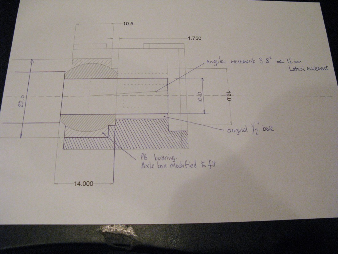
Well, this is the mod I am doing to the axle boxes to incorporate the spherical bearing. It involves machining away the rear of the axle box to accomodate the phosphor bronze outer ring to a depth that allows the inner ball to fit up to the shoulder on the axle and keep the axle box relatively in the same place it would have been. By keeping the original 1/2″ bore the axle is free to rotate about 3.8 degrees resulting in an estimated 13mm lateral movement from centre. The retaining screw will have to leave some clearance to avoid it jamming the radial axle movement and this will mean that there is a potential axial load being transferred from the axle to the axle box via the spherical bearing if the axle box does not move freely in its horns and the spherical ball is an interference fit on the shaft. I may chose to have a sliding fit to avoid that. Although not drawn the bearing does have a lubricating groove around its centre line and an oil hole and the axle box will have to have an appropriate oil hole to connect to it. (subsequently found to be impossible as the only bit of the axle box not covered by the slide plate is covered by the spring plate so no acces hole at the top. I will have to rely on grease packing in the axle box)

The next job is to do the machining and try it out……..
………. which has now been done and I am happy to say it all works fine. There is no obstruction to the lateral movement at all and the axlebox would slide out of the horns without restraint so I must look at that possibility as there is no restraint on the slide plates and I think the wheels could come against the frames. So the only natural restraint is the wheel flanges on the rail. The spherical bearing is a slide fit into the axle box and I will secure that with a drop of Loctite. The axle is a slide fit so the axle box can slide on and off the bearing ( needs to be as the wheels have to go on!). Just got to sort out the oil hole now and then I can think about the slide plates.
A recent find in a book on the Gresley Pacifics showed a section of the cartazzi axle box and also reported that the full size movement of the axle was 2 1/2″ inches which converted to 5″ gauge is 0.2″ (give or take a bit!) The cross section shown had no lower half to the bearing and it relied on the weight of the loco to keep the bearing down onto the axle. What was interesting was that above the bearing appeared to be a plate that could move against the top underside of the axle box and thus allow the axle to swing to compensate for the linear movement of the axle box in the horn plate. This seems to confirm another reference I found which talked about jacking up the axle box to remove the bearing for re-whitemetaling.
Anyway back to the job in hand ….. the slide plates. The bottom slide plate fits into the recess on the top of the axle box and is made from 1/4″ gauge plate. It is held in place with a 7 BA c/s screw at each end which is relieved down from the inclined plane of the plate. I just made the plate without machining the inclined plane as I planned to do all the inclined planes at the same time in one set up to ensure the angle were consistant.
Machining the 6 degree angle on the slide plate
The spring plate is made from 5/16″ gauge plate and has all the angles of the horn plates to be machined as it has to slide up and down the horn blocks as well as tranferring the loco weight onto the axle box. The final fit of this between the horns of this plate was down to hand finishing to get a free sliding plate but without slop.
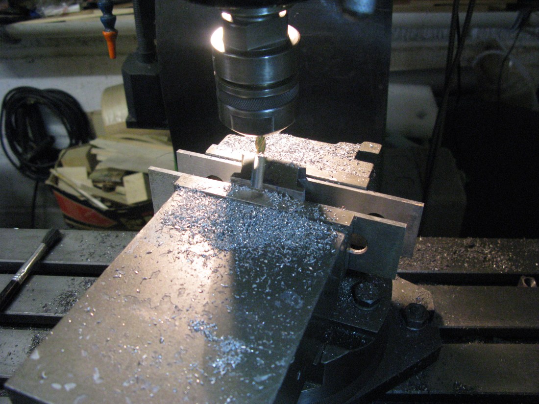
Having got the four plates basically made I then machined the inclined planes. The first was the slide plate. I used my tilt and turn machine vice set a tilt of 6 degrees and a pair of paralles under the plate in the vice jaws. Then just milled the surface and then back at the bench used a diamoned wet stone to put a nice finish on the surface.
Machining the slot in the spring plate
The spring plate was set up in the machine vice the same way but now the vice was swung to 17 degrees. The slot was then milled out and again on the bench finished off with a diamond wet stone.
The next test was to try the assemblies in the horns to see that the axle boxes moved freely. One did the other did not which seemed to be due to the slide plate jamming in the horn although it was quite free without the spring plate in place. The only reason that this could occur was for the angle of the slot in the spring plate being slightly out I thought. As the slide plate is not yet screwed down to the axle box this needs to be done before finding a solution ……… however I made the axle box keeps which are a single 5/32″ bolt through lugs at the bottom and with these in place and the axle properly assembled in the axle boxes the whole assembly seemed to work well when the axle boxes were at the bottom of their travel. So why the jam earlier? well I put it down to not having the axle properly fixed into the axle boxes and the axle boxes not being level across the frames. This raised a question in my mind as to what happens when one wheel rides higher than the other for any reason? I doubt that the full travel of the axle box in the horn vertically would occur with the other side at the bottom and trying the assembly with just a very small amount of misalignment seemed to result in satisfactory movement. What actually seemed to jam was the spring plate as that has to follow the horn block profile and being a reasonable fit as soon as it twists then it tends to jam. Perhaps a bit more clearance on the profile will be better.
The slide plates before having the 6 degree angle machined
The spring plate has a pin (the centre pop marks can be seen where it is located) which acts a spring retainer and a guide that fits into the dummy spring. I decided to leave fitting this unti the dummy spring assembly was fitted to the frame so I could check the centres were aligned. With everything assembled I relieved the spring plate clearance in the horn blocks by a couple of thou and that removed any tendancy for it to jam. The effect of this was to allow the spring block to move laterally in the horn block by the clearance. This confirmed to me that it was the angle of the recess in the spring plate being very slightly out compared to the slide plate that was causing the jam as the axle moved in and out. Anyway all is assembled and sliding OK both in and out and up and down.

The finished cartazzi axle box less the spring locating pin
