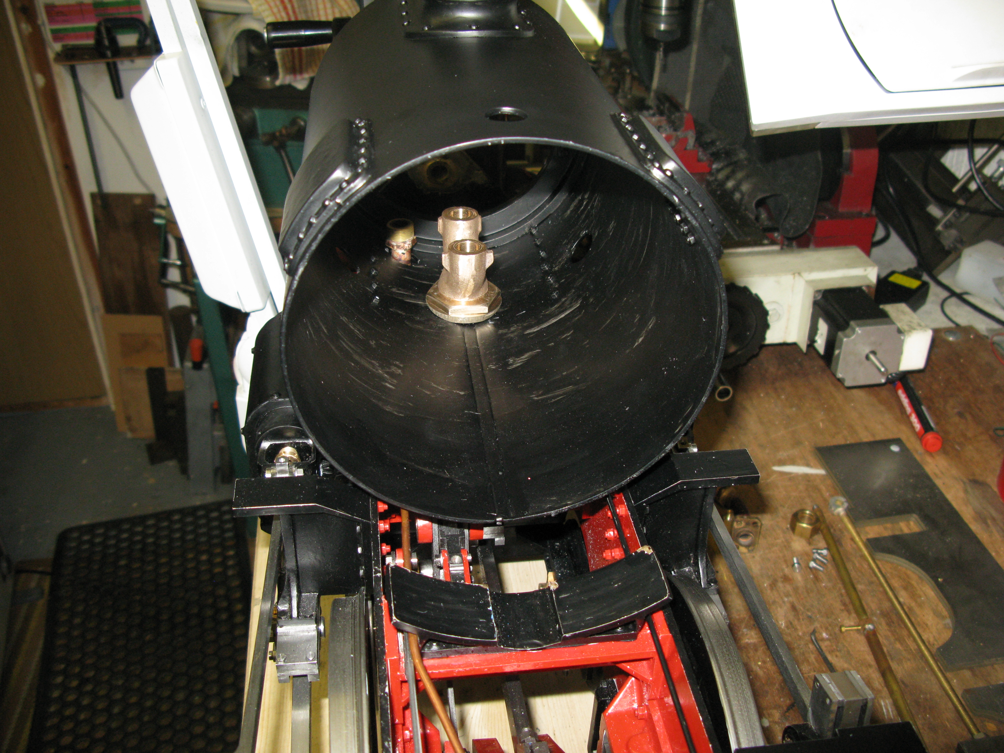
The smoke box is sheet metal 3/32″ thick and 6 1/2″ outer diameter. I could not source tube of that size and ended up having it rolled and the seam tig welded by a local firm.
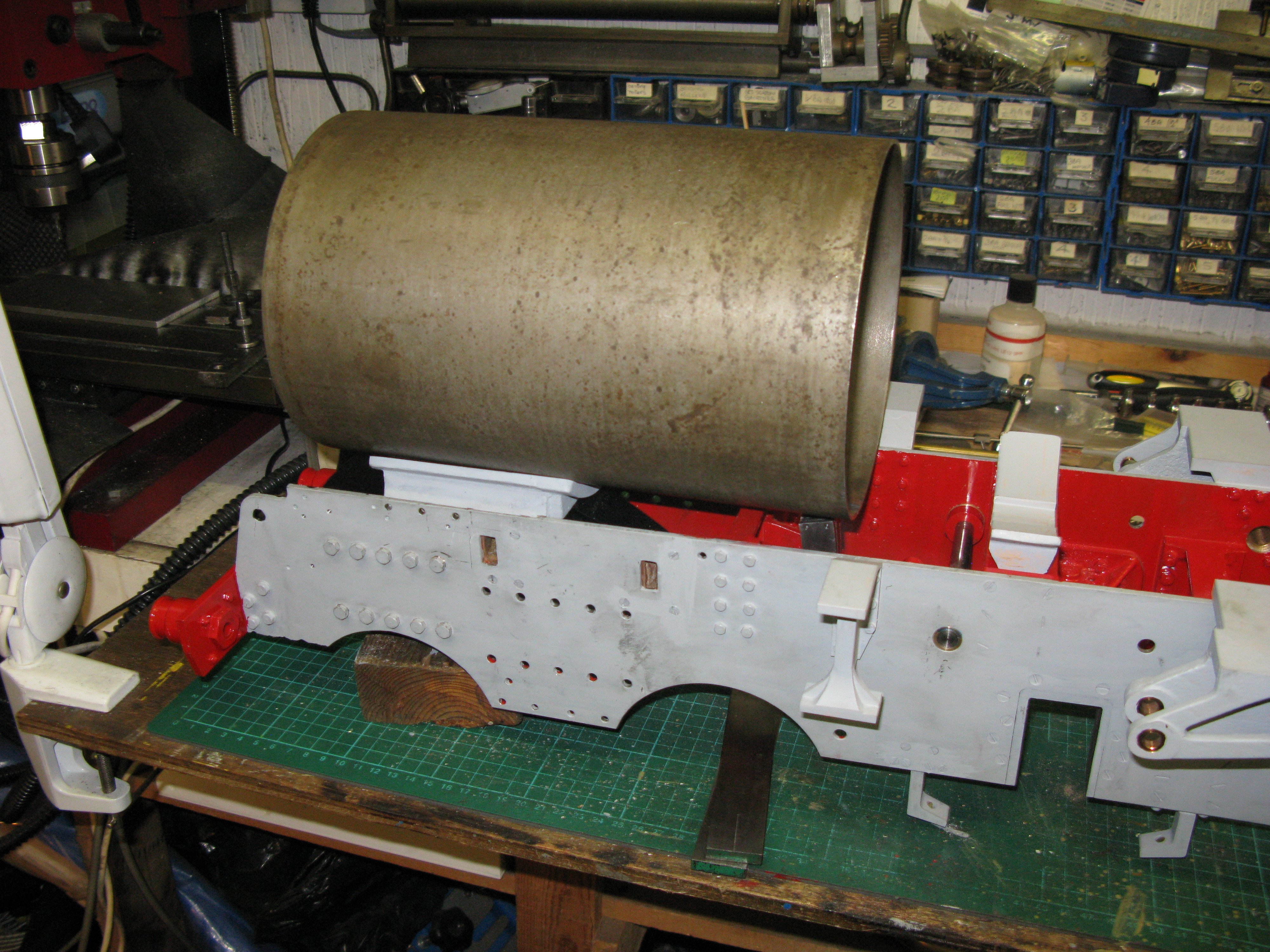
It fits the saddle neatly and just clears the expansion link as it should. (The smoke box saddle is described in the boiler chapter)
The steam pipe connections to the cylinders are my first real job in this section. They need to be made so I can connect an air supply to assist in setting the valve timings.
There is no dimensioned drawing of the steam pipes other than the flange that bolts to the cylinder and a note to use 7/16″ OD by 20g pipe. There is a general arrangement view of an end on front view of the cylinders that depicts the pipes and it shows the outside cylinder pipes vertical from the cylinder and then bent in through the smokebox and the inside cylinder at a very slight angle towards the right hand cylinder.
Looking at the full size A1 the outside steam pipes are encased or clad and the casing is at an even angle from the cylinder to the smokebox. I need to find out a bit more and decide if the pipes need to be as drawn or put at an angle direct from the cyinder.
The connecting flanges are made from PB and consist of an rectangular slab held in place by four 3 BA set screws to the cylinder block with a 1/8″ deep pip to fit into the cylinder block steam hole and a 7/16″ dia recess to accept the steam pipe silver soldered in place.
The connections inside the smokebox are a screwed union but there are no drawing details for their manufacture so I have to design my own. (post note: I did eventually find the detail drawn and it was virtually the same as the ones I made but marginally larger).
A couple of sleeps and a bit of thinking and I have decided that the steam pipes have to be made as drawn as to make them at an angle would bring them too low in the smoke box as the flanges are close to the frames. So to make the external steam pipes look similar to the full size the cladding will have to be made so it slopes at the right angle and encases the steam pipe. An added complication is the steam oil injection is at the back of the steam pipe so the cladding has to have a cut out to accommodate that. I can see lots of of paper/card formers being made!

General arrangement of steam pipes. On the right is my pencilled form for the cladding.
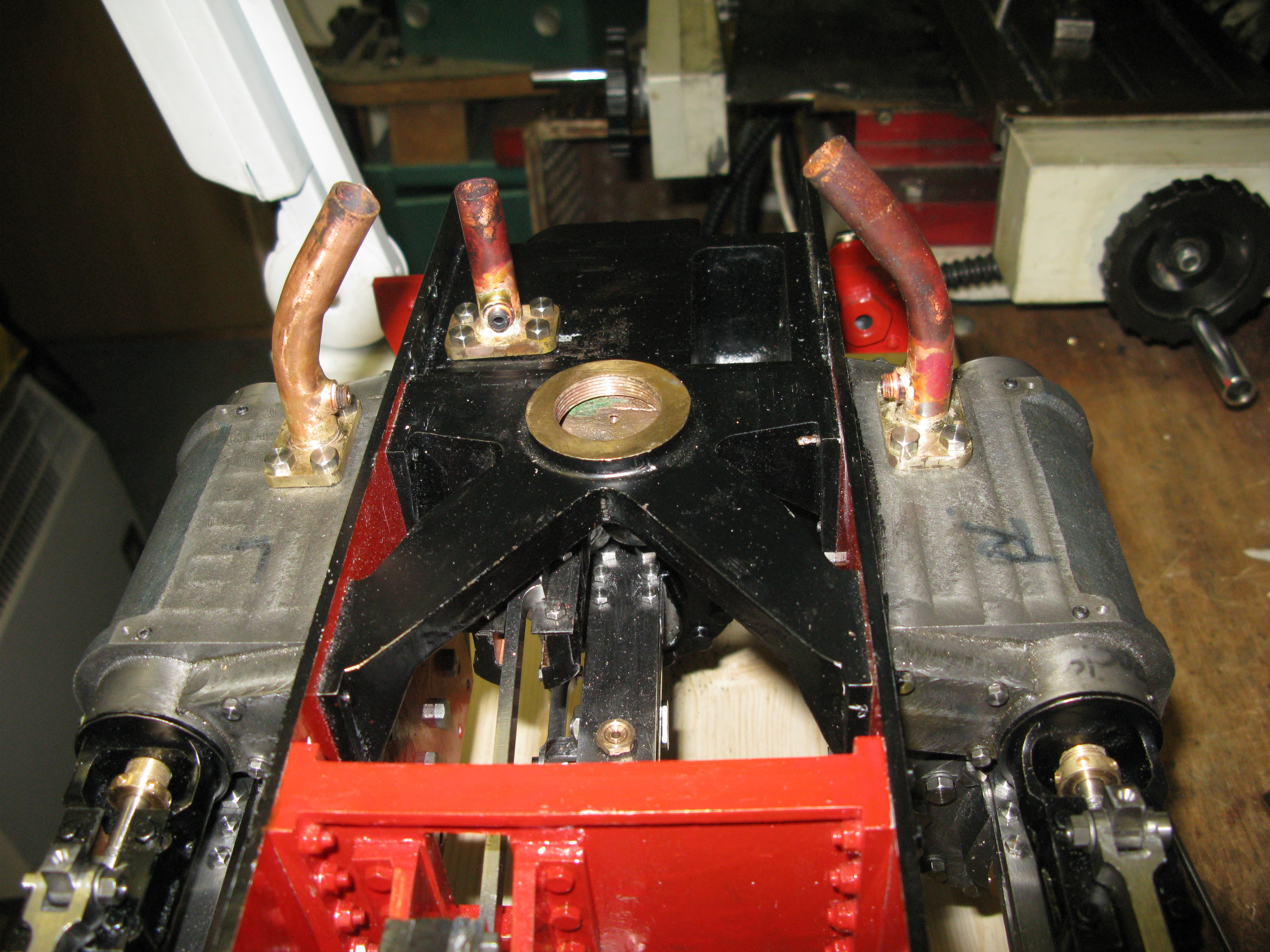
The three steam pipes temporarily fitted so I can blow air into the cylinders for timing.
The three steam pipes have been fitted temporarily and left too long for eventual fitting of the unions. They have now been used to blow air at low pressure into the cylinders to roughly set the valve timing by feeling the air coming out of the drain cock holes.
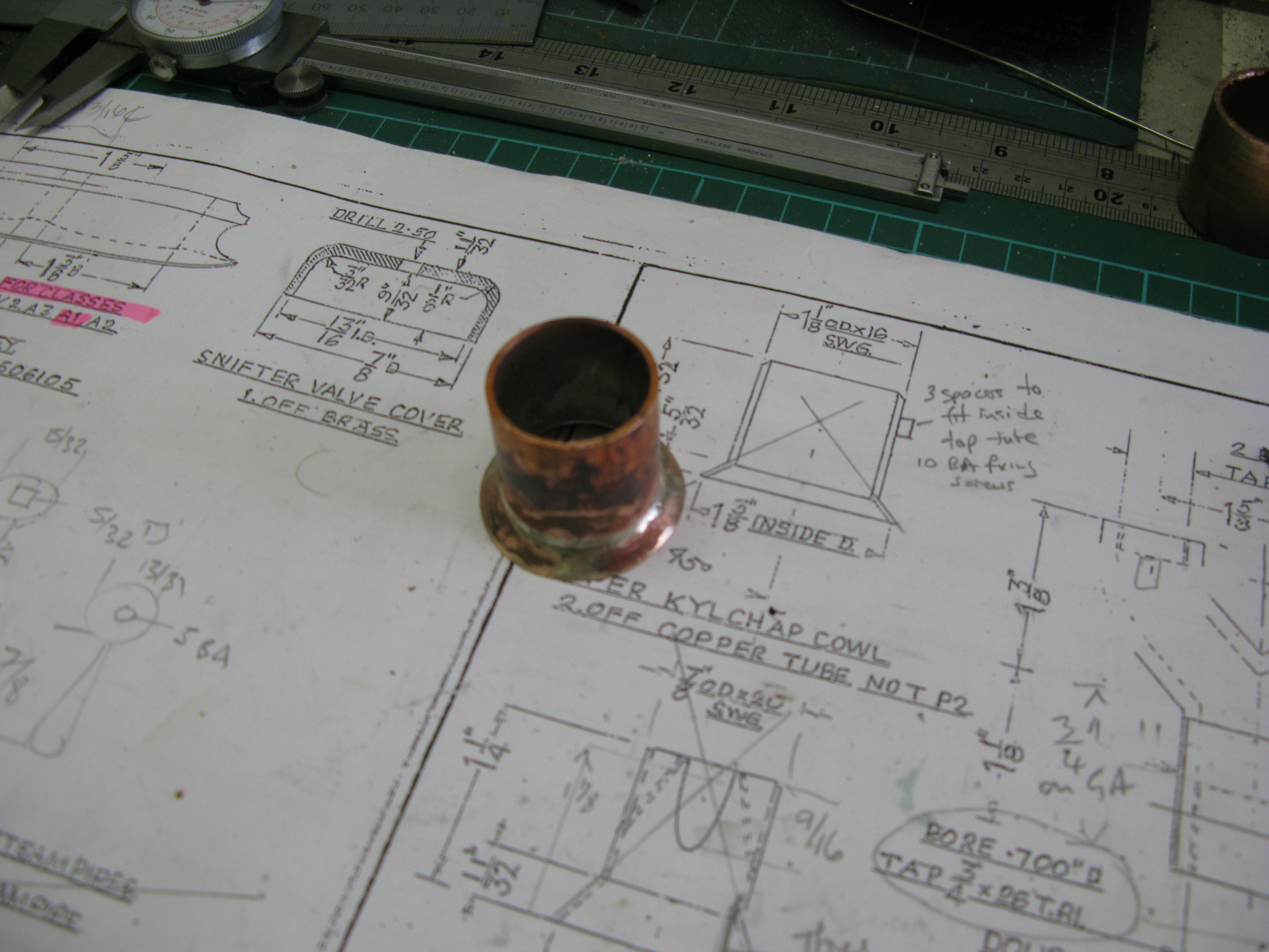
The steam fittings for the steam pipes have been made to my own design. Nothing clever here just the sizing and thread to use. The connection thread is 9/16″ x 26 tpi and all threads were screw cut on the lathe.
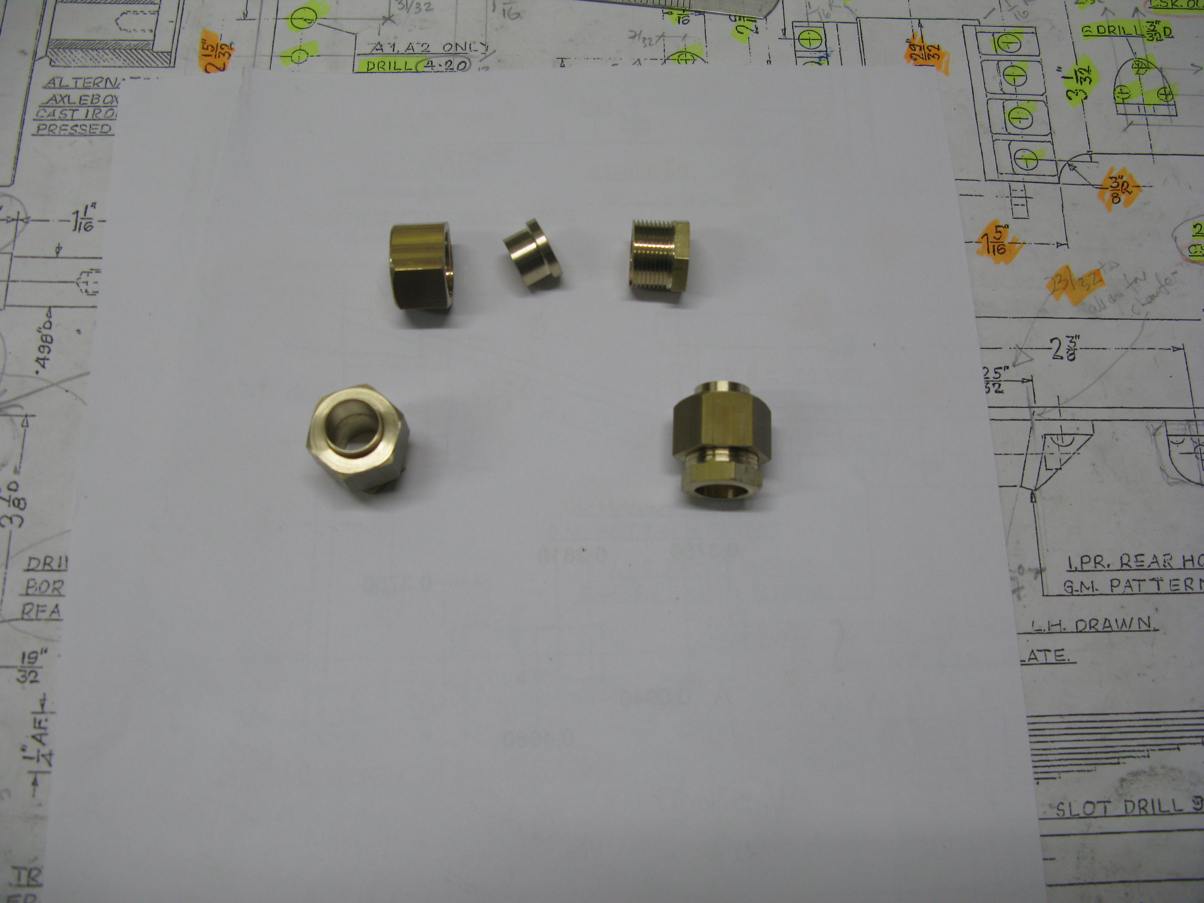
The but joint that occures between the mating parts will have a fibre washer to provide the seal.
Right hand item is silver soldered to the pipe connecting to the cylinder and the nipple to the pipe from the steam header.
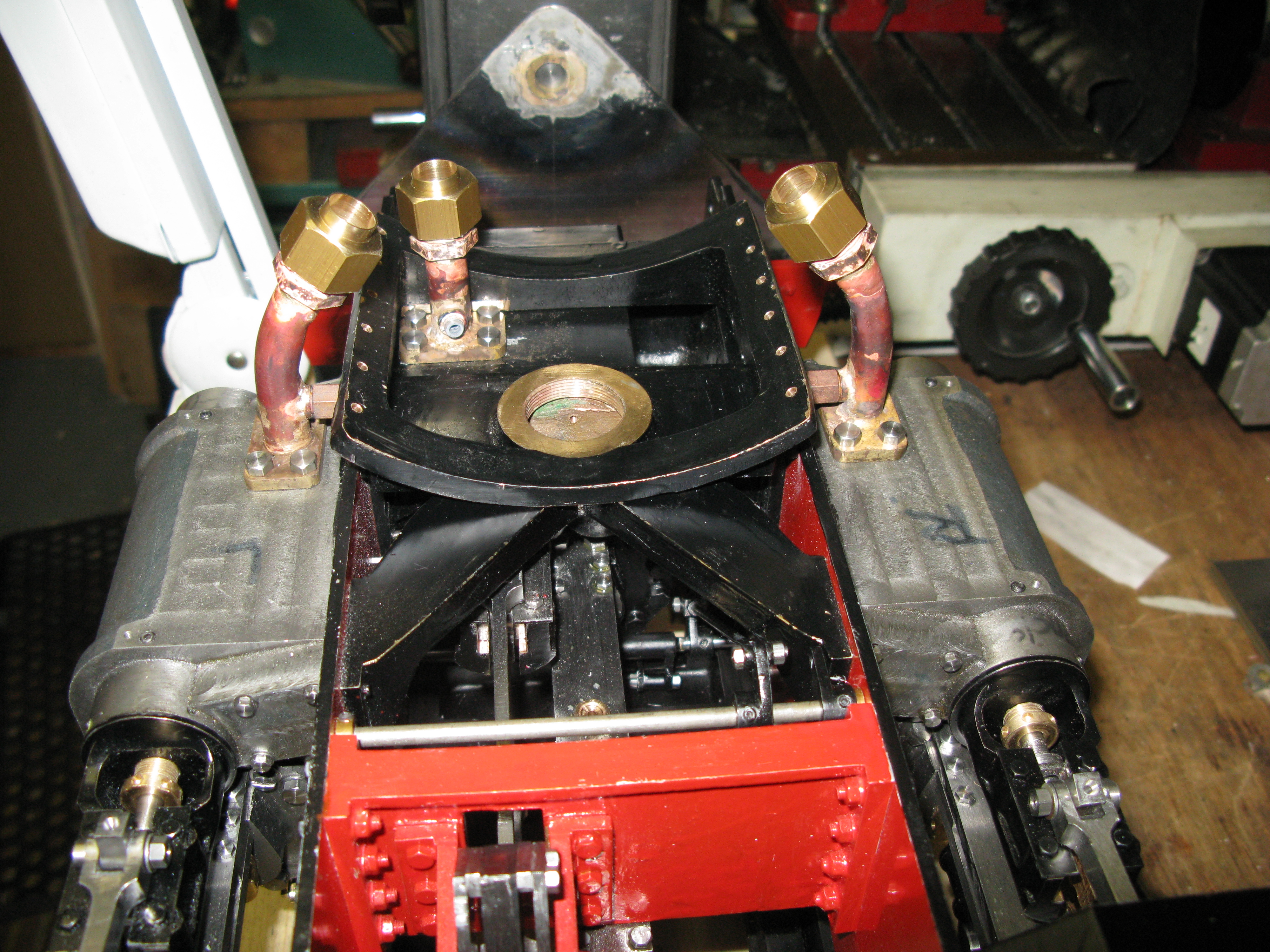
All fittings silver soldered in place
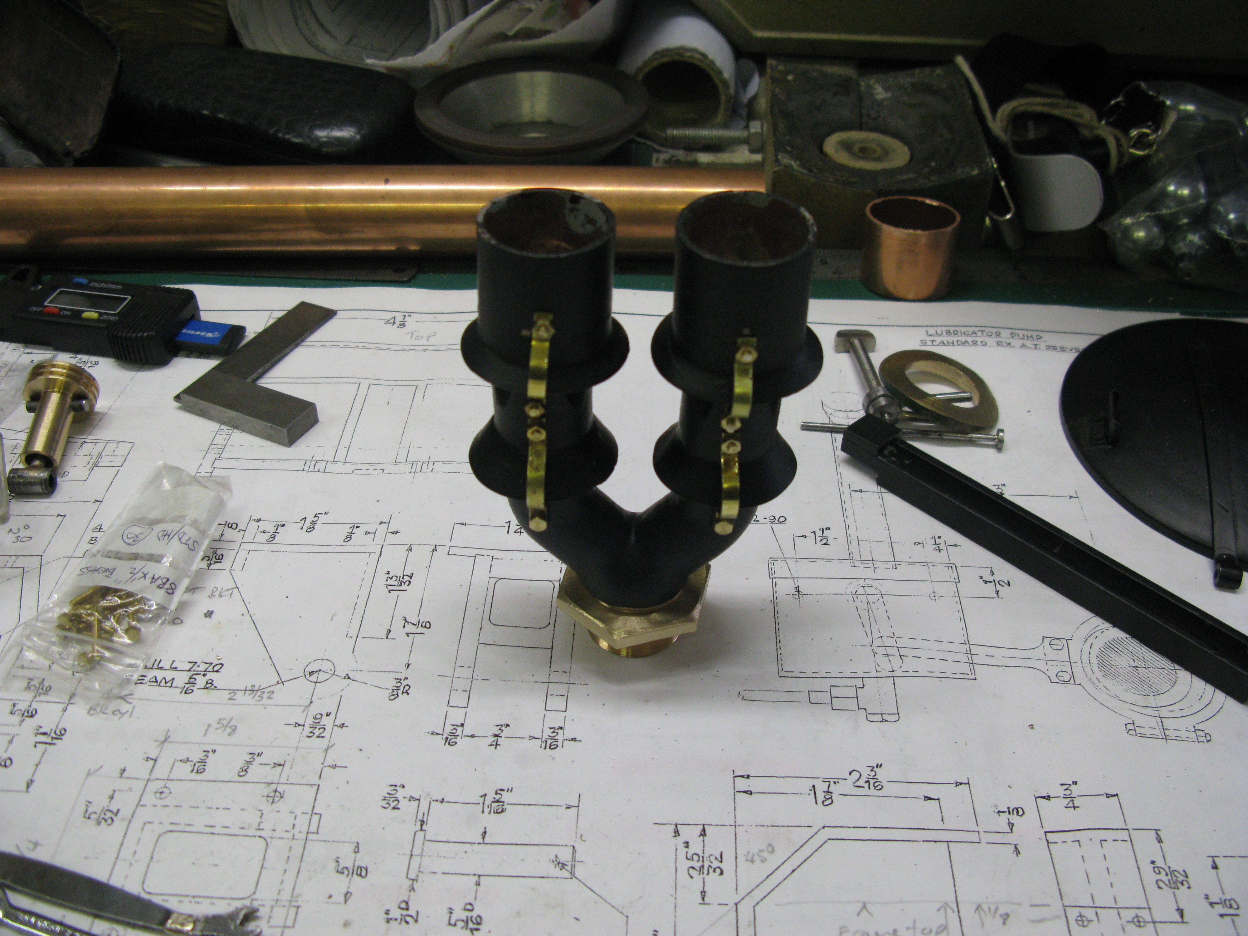
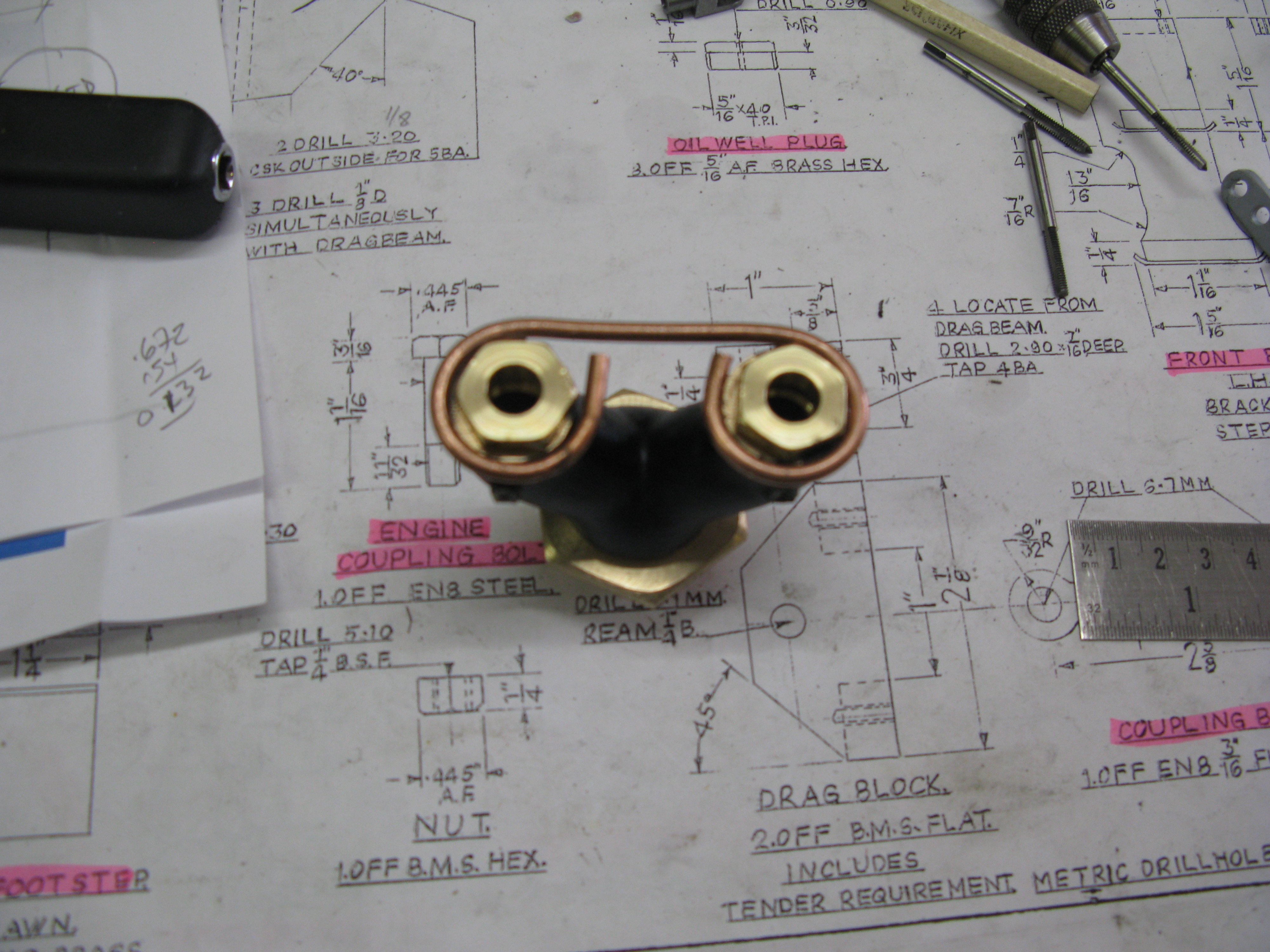
The next job is to make and fit the non return valves for the steam lubrication that fit onto the base of the steam pipes. The screwed nipples are just visible with caps on them at the moment (except the middle cylinder).
The drawing calls for the non return valve for the middle cylinder to be fitted on the steam pipe under the smoke box. I felt that this was potentially a problem if the non return valve failed for any reason as it would be inaccessible. So mine will be fitted in line further back in the pipework.
Details of the lubrication pipes are in the Lubrication chapter.
The time has come to drill the holes in the smokebox so I can then mount it on its saddle and jig drill from the saddle for the fixings. This will enable me to finally fit the saddle to the main frame.
The first hole to be drilled was for the steam exhaust which needed to be 1 ” clearnance and set back 2 15/16″ from the front of the smokebox.
To do this I set the smokebox up on the mill bed a clamped it down at each end at the smoke box bottom. To get the centre line of the hole to be drilled set at the top of the box so it was truly on the vertical I used the measuring jig as shown below.
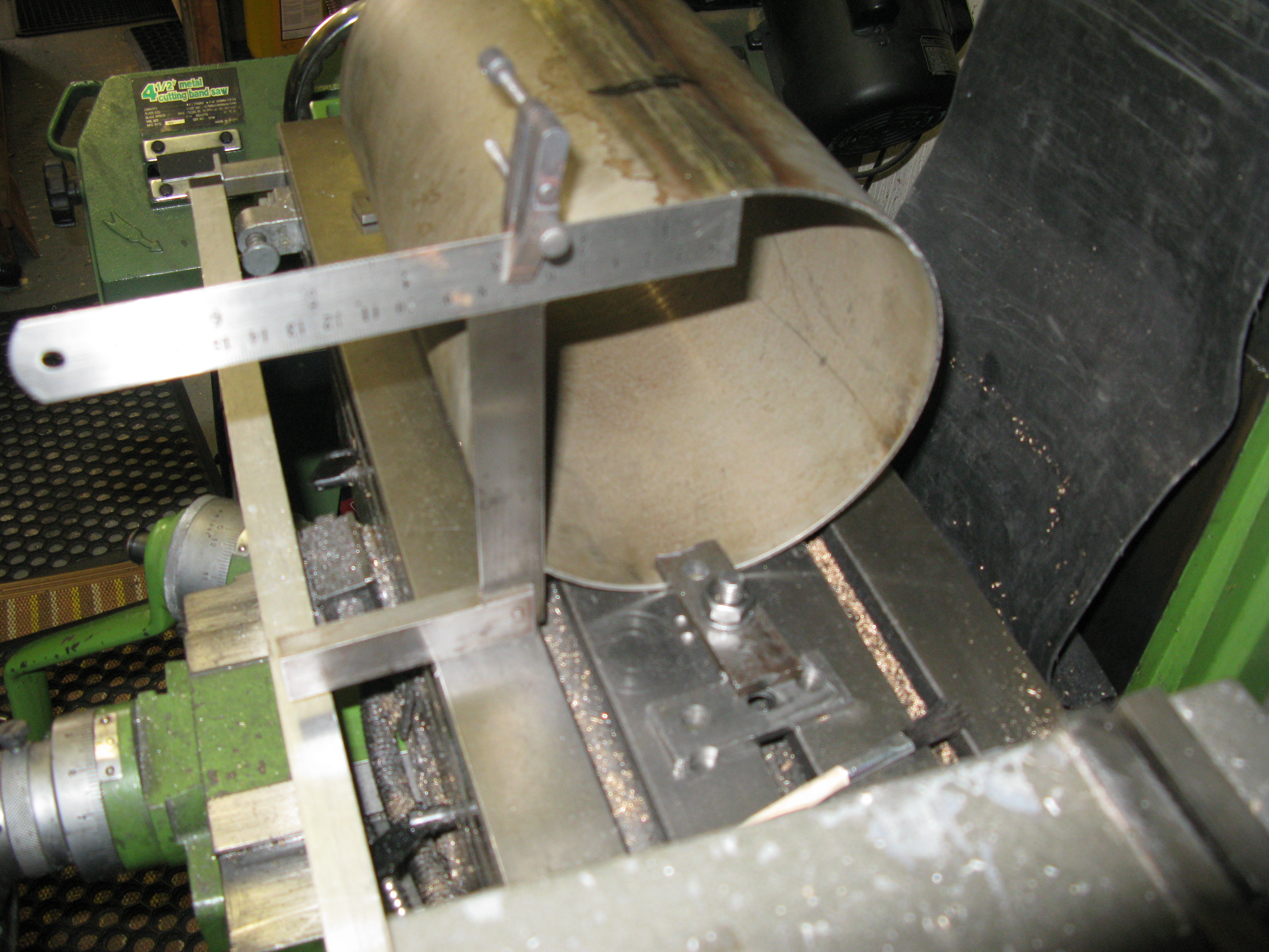
The square has the ruler set so it is clamped exactly at the smokebox radius and with the edge of the square aligned with the edge of the smokebox the centreline should coincide with the end of the ruler. This done the pilot hole was drilled.
I used sheet metal cutters to make the holes. These are cone shaped cutters and come in various sizes so for larger holes you just work your way up using the next size up cutter.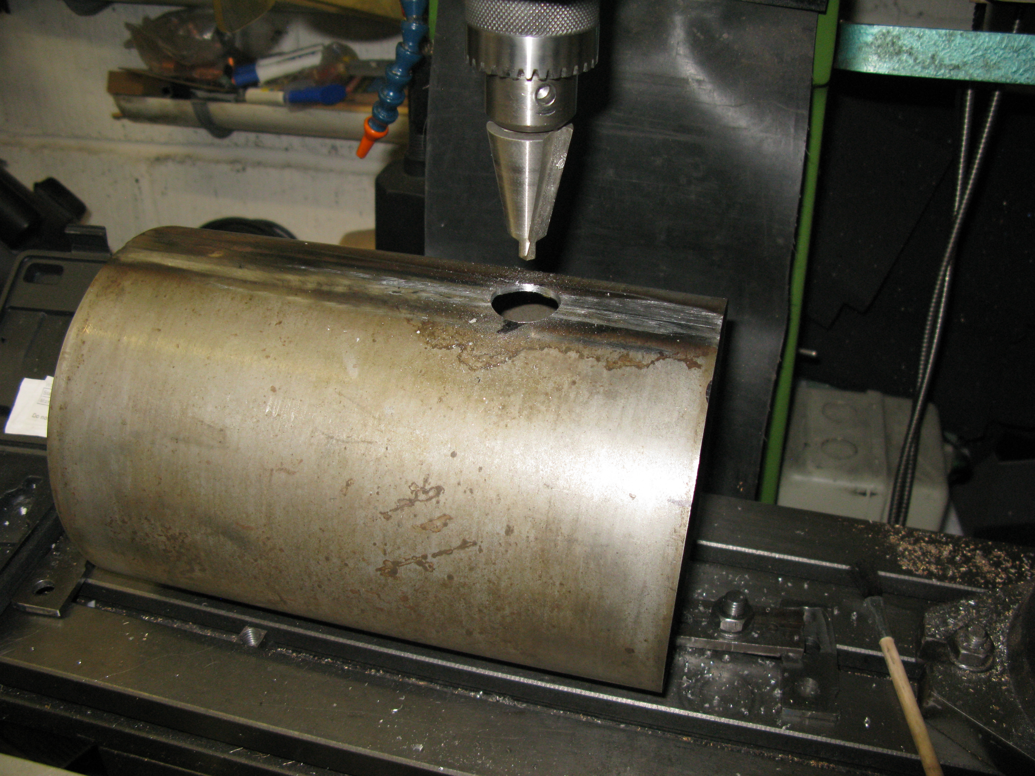
Here the final cut has been taken to get the hole diameter at 1″ clearance for the kylchap blast pipe to be screwed through into the boss in the K exhaust chamber.
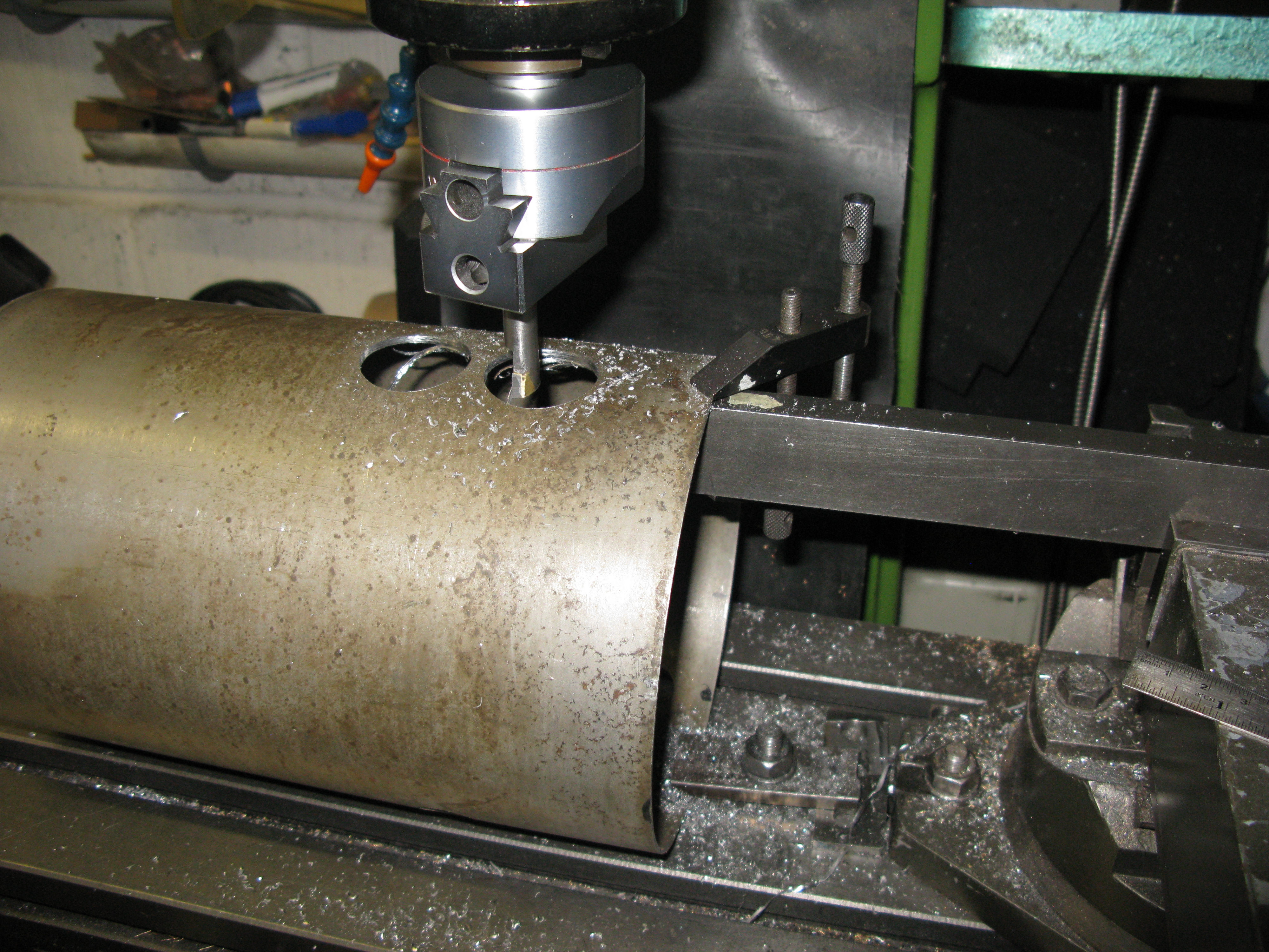
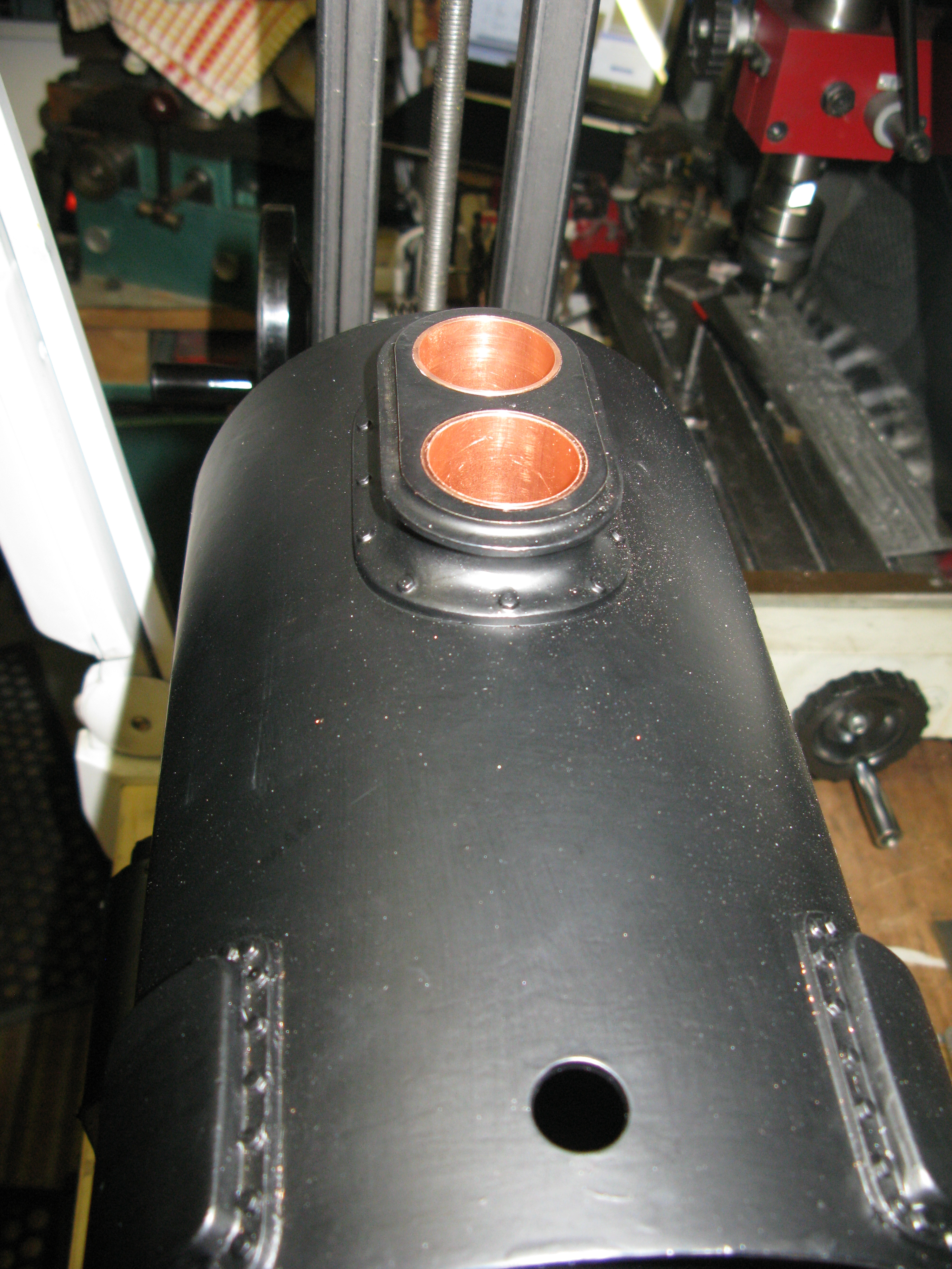
The holes for the steam pipes were similarly drilled.
However the holes for the double chimney required an additional maching operation as the cutters I had were not large enough to cut an 1 3/8″ hole so the final enlargement of the holes had to be done with the boring bar. Now this process has a whole set of different forces acting whilst cutting and the smokebox top was not sufficiently secured to prevent it moving. Cone cutters by their nature exert a self centering force so the other holes were OK.
To secure the top of the smokebox I used the machine vice with a stout bar clamped in it and under the top of the smokebox which in turn was clamped to it by a jewelers clamp.
This made it rock solid and the final boring could take place quite safely.
The next job was to jig drill the smokebox from its support saddle. In order to get the smokebox in the right position it was mounted on its saddle on the frames in the correct place and two jewellers clamps used to secure the two parts together.
It was then removed from the frames and onto the mill table for jig drilling with an additional clamp added at the rear of the saddle.
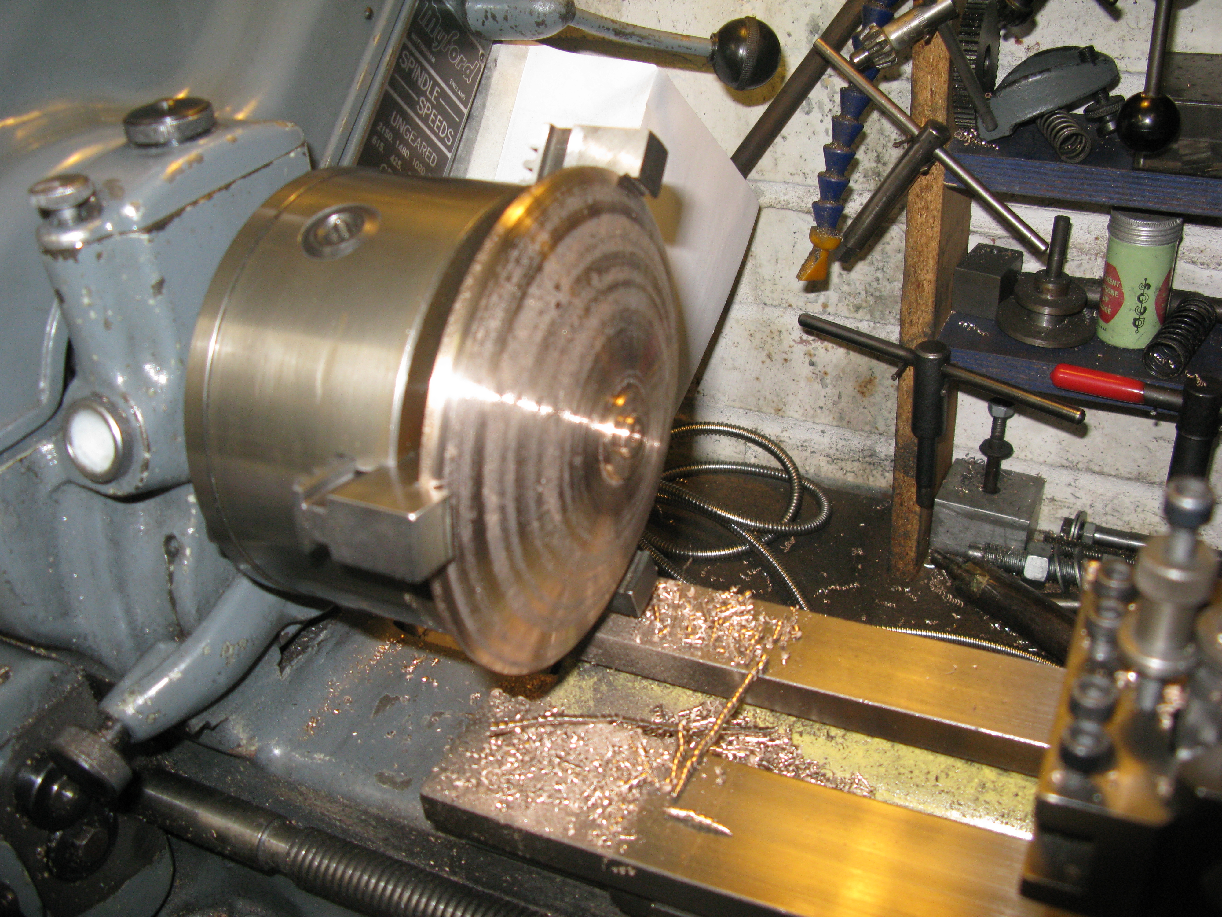
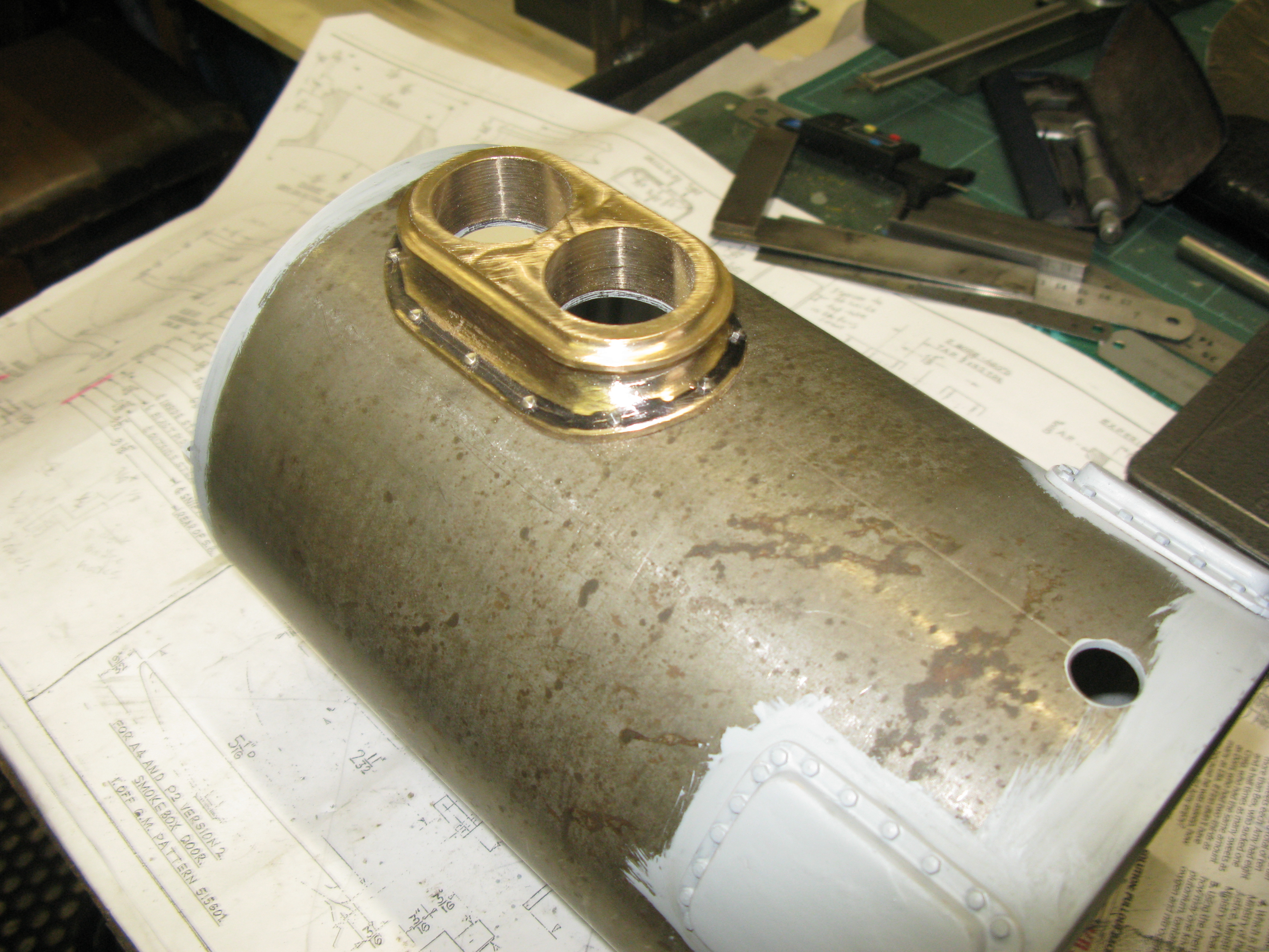
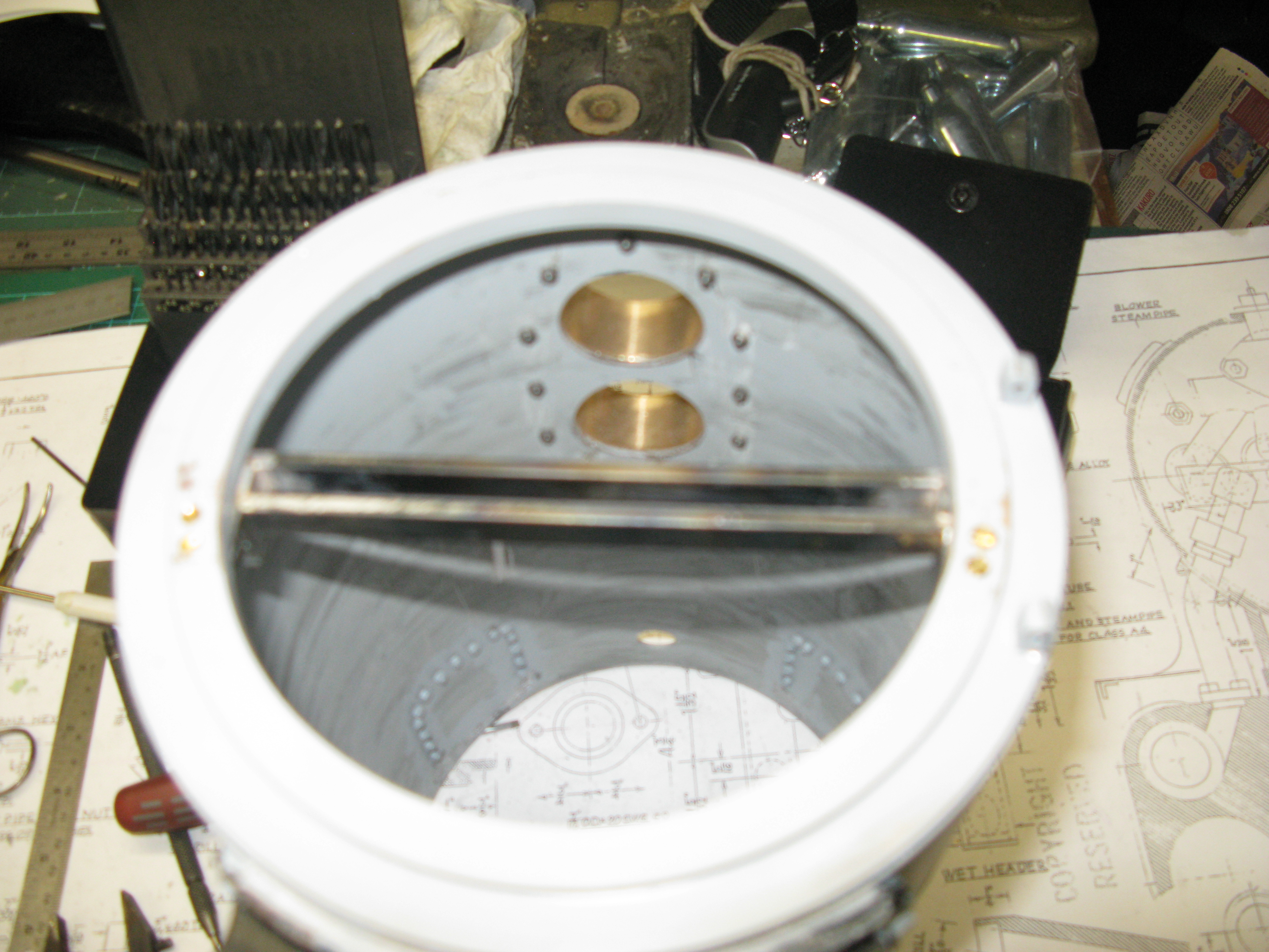
My next task was to turn the door ring. A gunmetal casting, and this was mounted on the lathe using a three jaw chuck gripping from the inside of the casting.
This eanble the front of the ring to be machined to the required dimensions and just a truing cut taken on the rear dimension. The inside bore was also not full depth as the chuck jaws prevented the boring tool going too deep. Having got to this stage the ring was turned around on the chuck to finish off the machining.
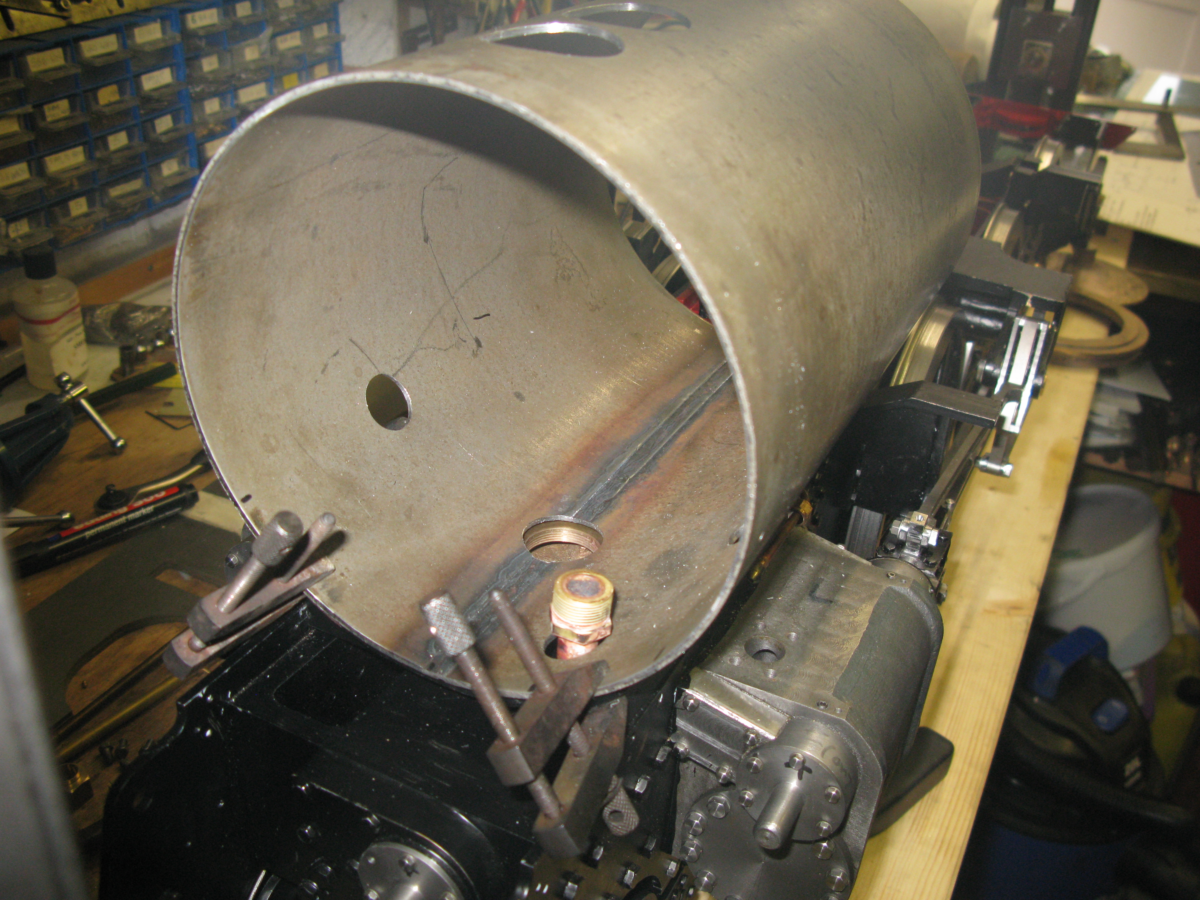
The finished ring was inserted into the smokebox and proved to be a good fit.
To fix the ring into the smokebox I ran some loctite around the inside edge so it could by capilliary action fill up the few very small gaps that were visible and three 7BA c/s screws were put in one on each of the centre lines of the chimney and steam pipes.
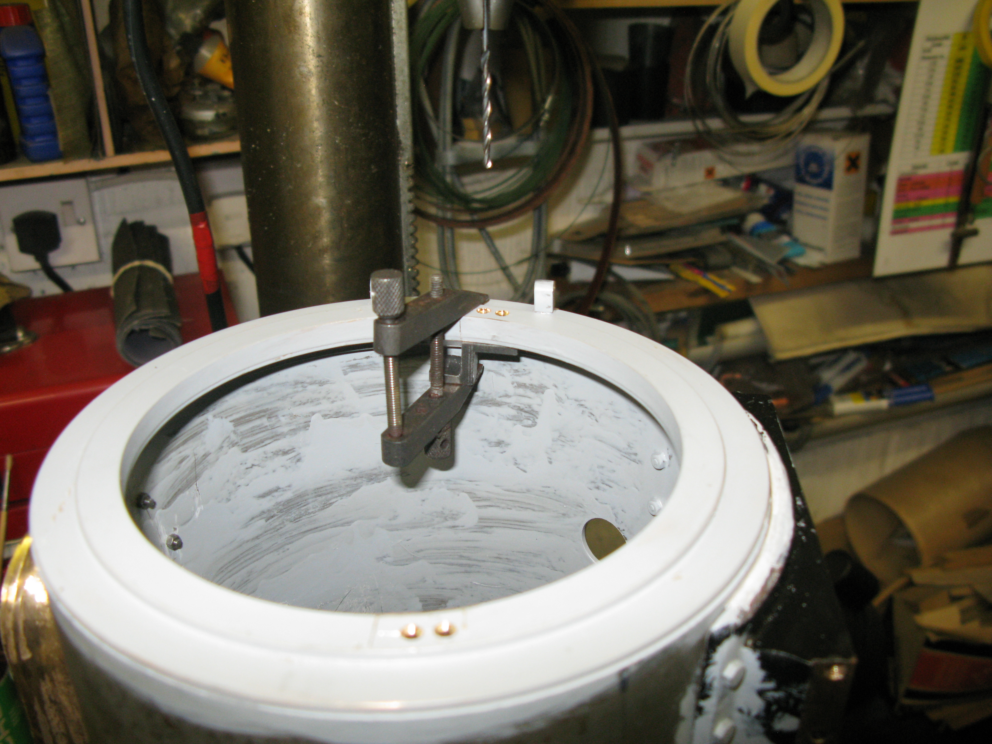
The door and its hinges presented me with a problem. First the position of the hinges as dimensioned proved to be impossible as the top hinge would have ended up right on the outer edge of the inner ring, the bottom hinge on the outer ring was OK.
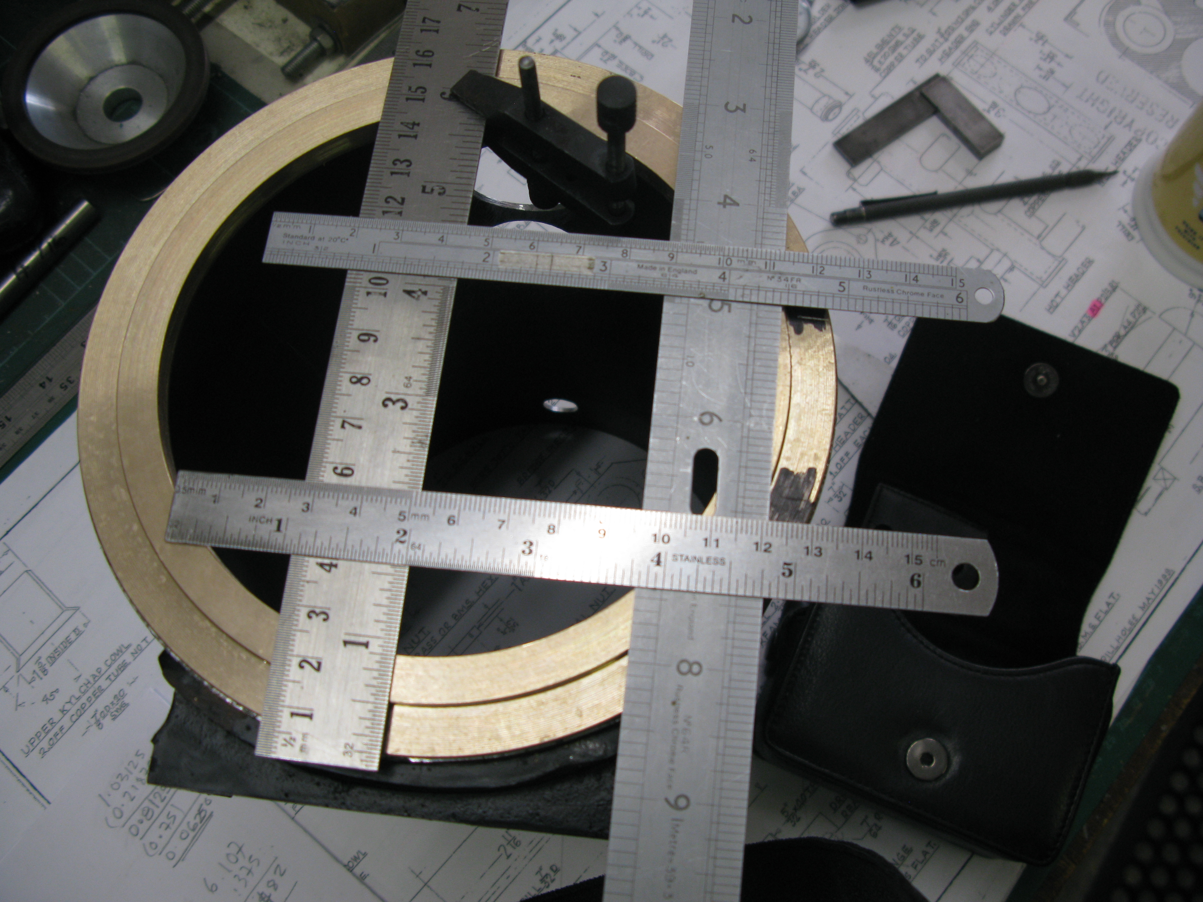
The intersections of the rulers on the right hand side show where the hinges should be according to the drawing.
My solution to this was to move the hinges outwards by an 1/8″ but it did bring the bottom hinge close to the outer edge. The hinges are made from 1/4″ square steel and they screw into tapped holes in the ring (although the drawing does not show this), this is inferred as the thread on the hinge is not long enough to go through the ring and put a nut on the other side. The dimension for the hinge cenre line away from the ring face as drawn is 3/16″. This would place the hinges on top of the inner ring as the door drawing shows the hinge 3/16″ from the door face. Again, this was not a feasable design so the hinge centre line dimension was made bigger so as to fit on the outer ring and still give 3/16″ from the door face. I decided to finish the door before proceeding to make the hinges.
Having made the decisions on the hinge arrangements I turned to machine the door. This is a gun metal casting with a boss to enable it to be gripped in the chuck for turning. The problem was that the cast boss was not true with the door and it was impossible to get the door to run reasonably true for turning. To overcome this I used a boring head in the mill and cutting the boss with the door casting clamped to the mill table flat and centralised under the quill to get the boss machine sufficently true to enable it to be clamped in the lathe chuck for eventual turning.
With this done turning the door diameter and facing it off was straight foreward. Turning the work around in the chuck using outside jaws on the door diameter enabled the boss to be turned away to give the slightly raised bosses for the dart clamps. The curvature of the door was a reasonable finish as cast so I just used a file to provide a smoother surface.
Turning the diameter and facing off
Cleaning up the door front and drilling for the dart
Back to the hinges. The straps that fit across the door are dimensioned at 7/32″ wide and 13/16″ away from the centre line. Now putting straight pieces of MS bar across a domed surface results in the outer ends coming closer together than at the middle, just like the lines of longtitude on the earth, they meet at the poles but are farthest apart at the equator. To overcome this natural effect I made the straps up from 1/4″ wide x 1/16″ MS flat. The straps were cut longer than required at this stage and then clamped in place on the door, drilled for 8 BA c/s screws and fitted in place. The straps were then filed so as to provide a parallel pair when looking straight onto the door.
The hinge bosses at the end of the straps were turned 1/4″ dia. with a 3/32″ bore and the hinge pin also made from 3/32″ MS rod with its 1/4″ x 1/16″ cap silver soldered in place.
The door was then offered up to the smokebox ring and centralised and the straps marked off were the hinge bosses needed to be placed to line up with where the hinge pins would be located. Having cut the straps to length the door, hinge bosses with a 3/32″ rod through them were aligned on flat faces for silver soldering. It has to be done on a flat face to simulate the door ring so the bosses are at the correct height so when the door is closed it finishes flush with the ring. Also the straps are at an angle on the hinge bosses due to the geometry of the curved door meeting a horizontal surface.
Silver soldering the hinges to the straps
The hinge pins were made from 1/4″ sq. MS with a 5/32″ x 40 x 3/16″ long threaded portion to screw into the smokebox ring. The actual total hinge height was measured by vernier from the top of the hinge boss on the strap to the surface of the door ring which then gives the measurement of where the hole for the hinge pin has to be drilled.
The hinge is then reduced to 7/32″ sq. and rounded off at the top to match the strap hinge boss.
Finally the holes to accept the hinge pin are drilled and tapped and the hinge pins fitted.
Place the door in position slide the hinge pin in and voila the door fits flush and opens nicely.

The fitted door.
There is more work to be done on the door but I am leaving that for now and moving on to do the superheater access covers and chimney.
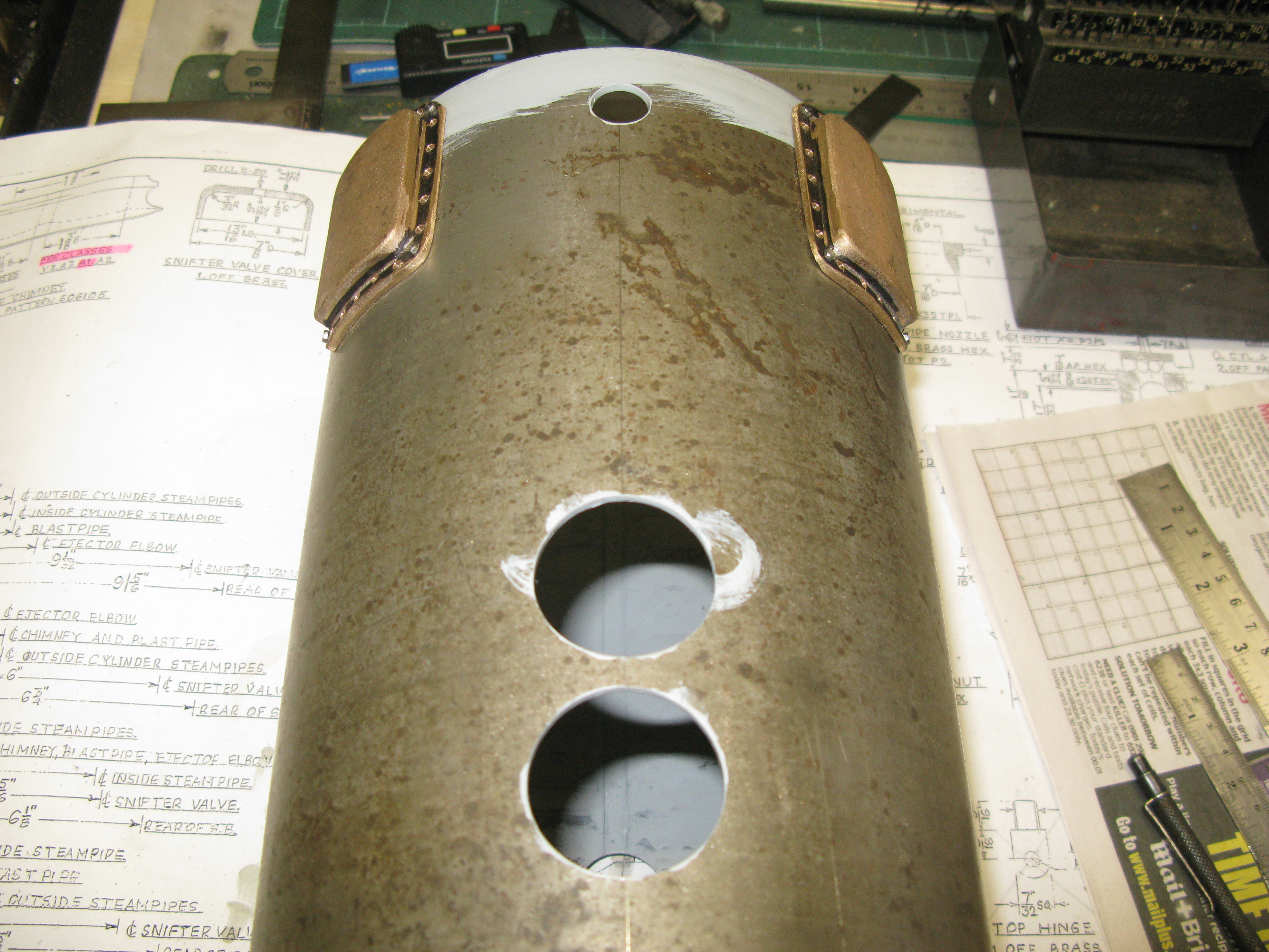
The superheater access covers are a gun metal castings. The casting requires the smokebox radius to be machined in order for it to fit. There are also 20 8BA (small head) bolts to hold it in place.
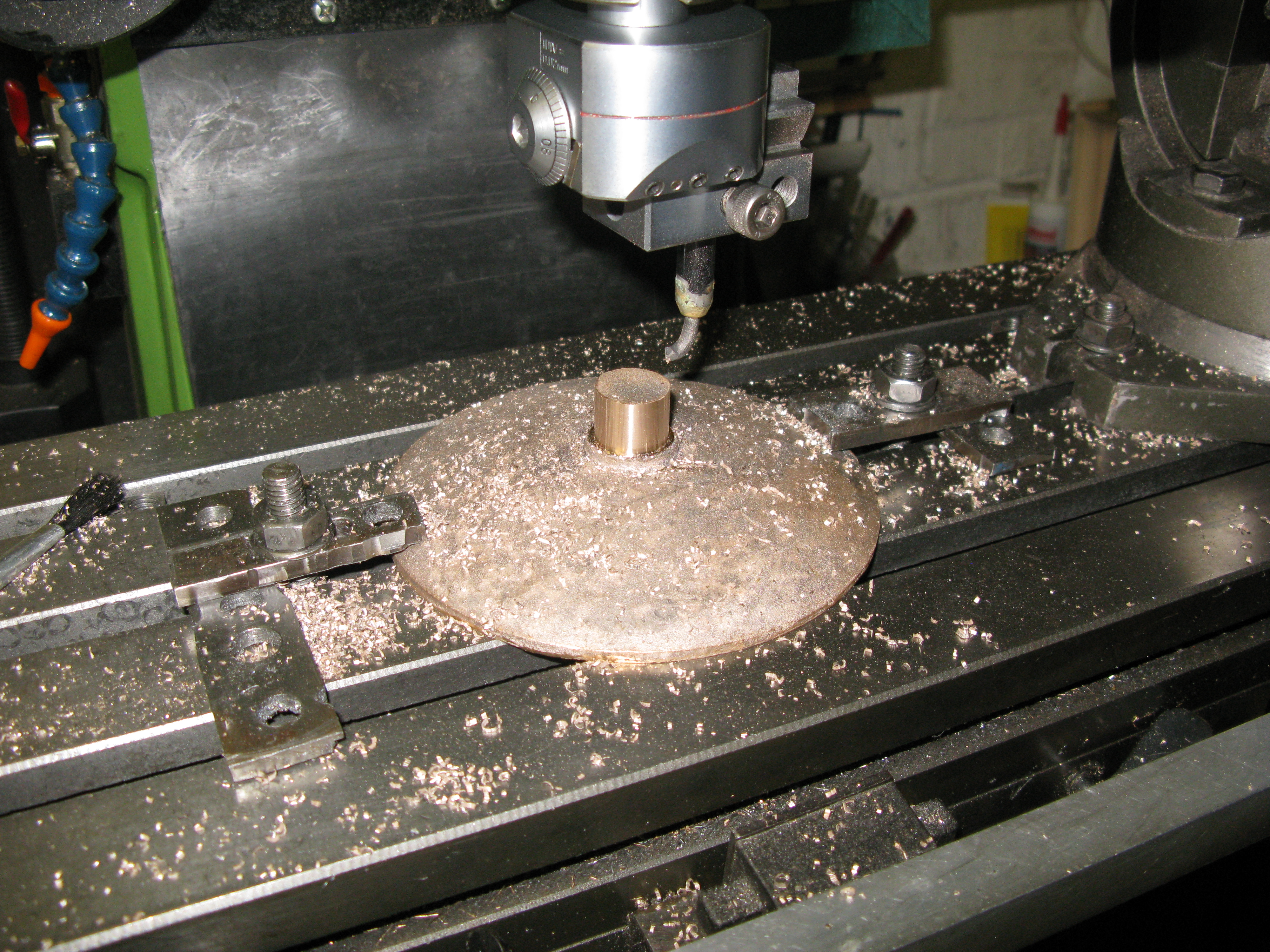
The radius was fly cut with the boring head as can be seen in the photo above after which the fixing holes were drilled and the smokebox jig drilled by clamping the cover in place.
The position of the covers on the smokebox is not detailed on the drawings. Its angle can be determined from a GA of the front view but not its longitudinal position. I resorted to looking at photos of the full size and determined that they were very close to the end of the smokebox so that’s where mine are fitted.
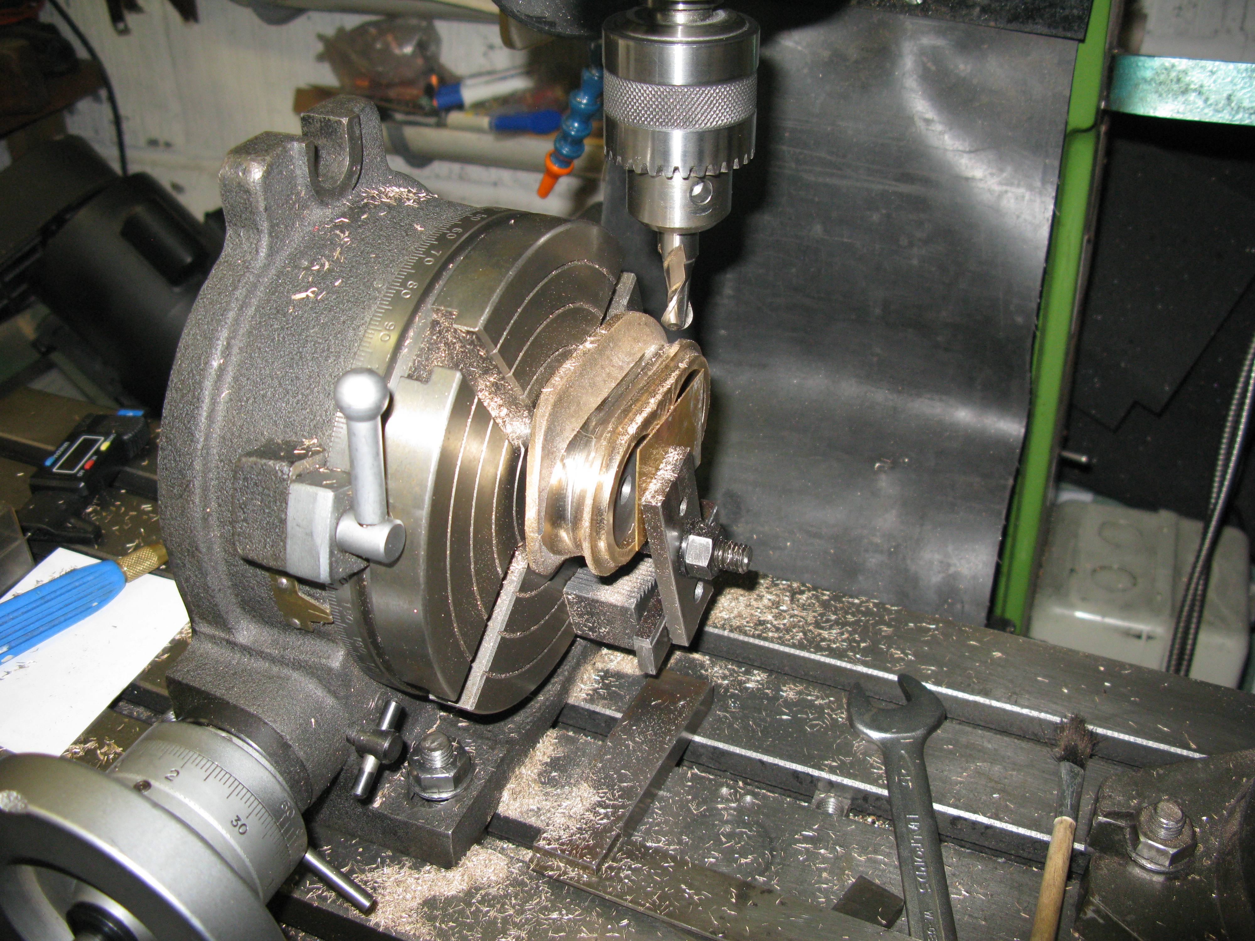
Next was the chimney. This too is a gunmetal casting but it has the smokebox radii cast in. The casting was a bit of a problem as the cores for the holes were not cast centrally with the mould line. After a bit of head scratching on which to use as a centre line I chose the mould line as there was plenty of material in which to make the bores but as the mould line also had more material on one side than the other there was clearly going to be some serous cleaning up to do.
The first machining task was to machine the bores.

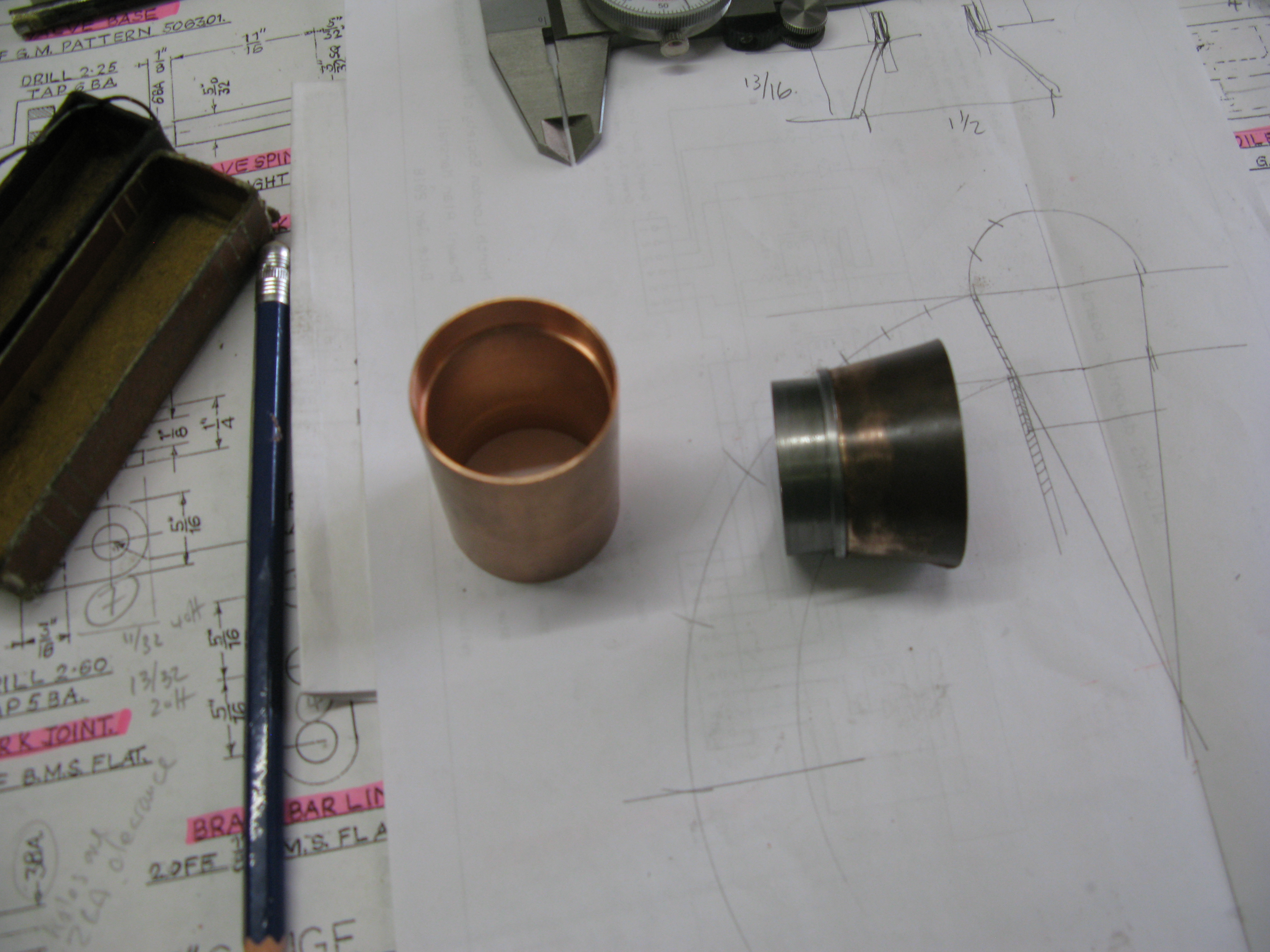
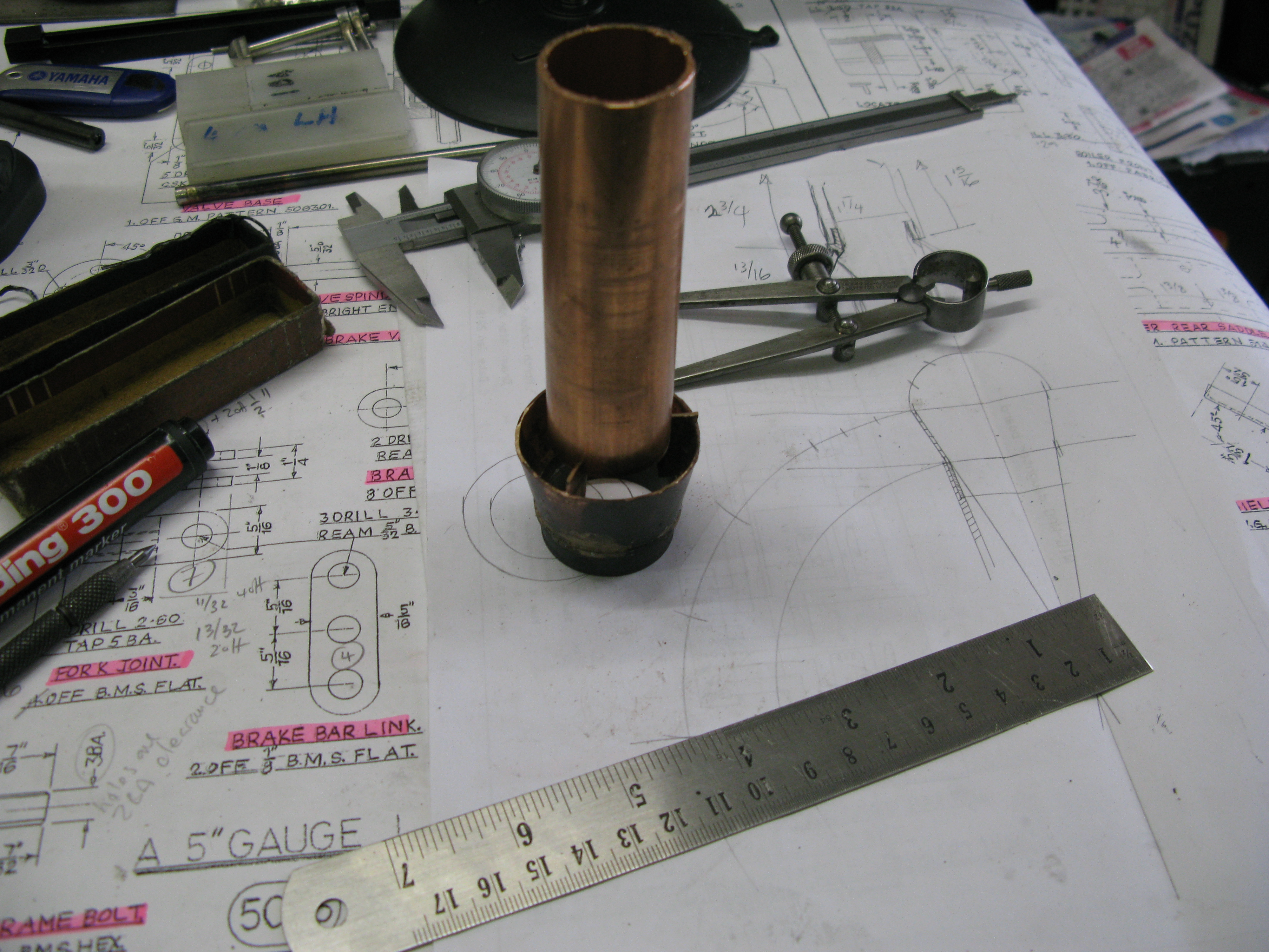
The bores are 1/38″ dia. and the Kylchap chimney top slides into them. I used a piece of copper tube as a check gauge to ensure the finished bore would enable the tube to slide in without being too tight.
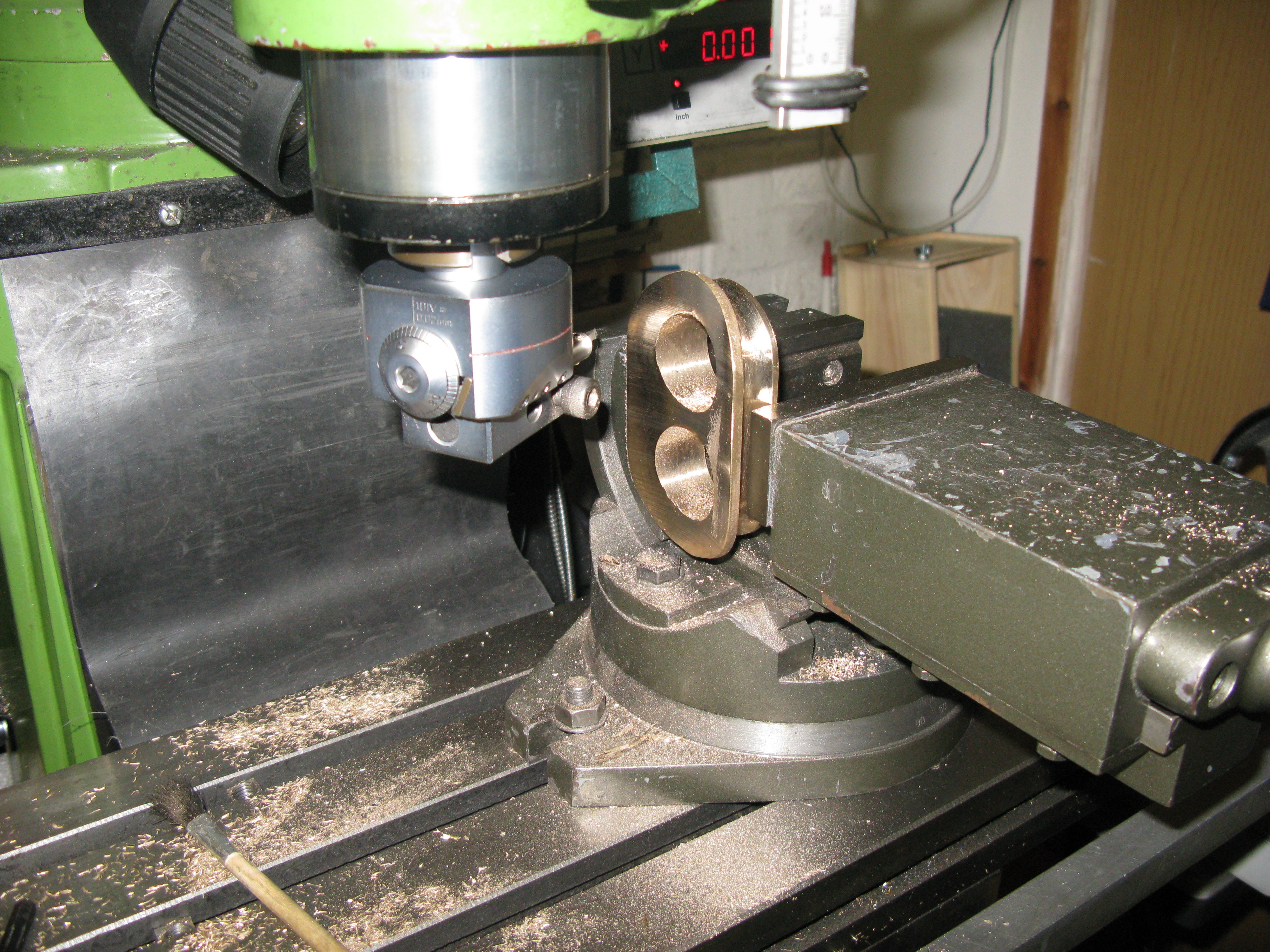
Following this the top was machined flat and the contour of the lip machined.
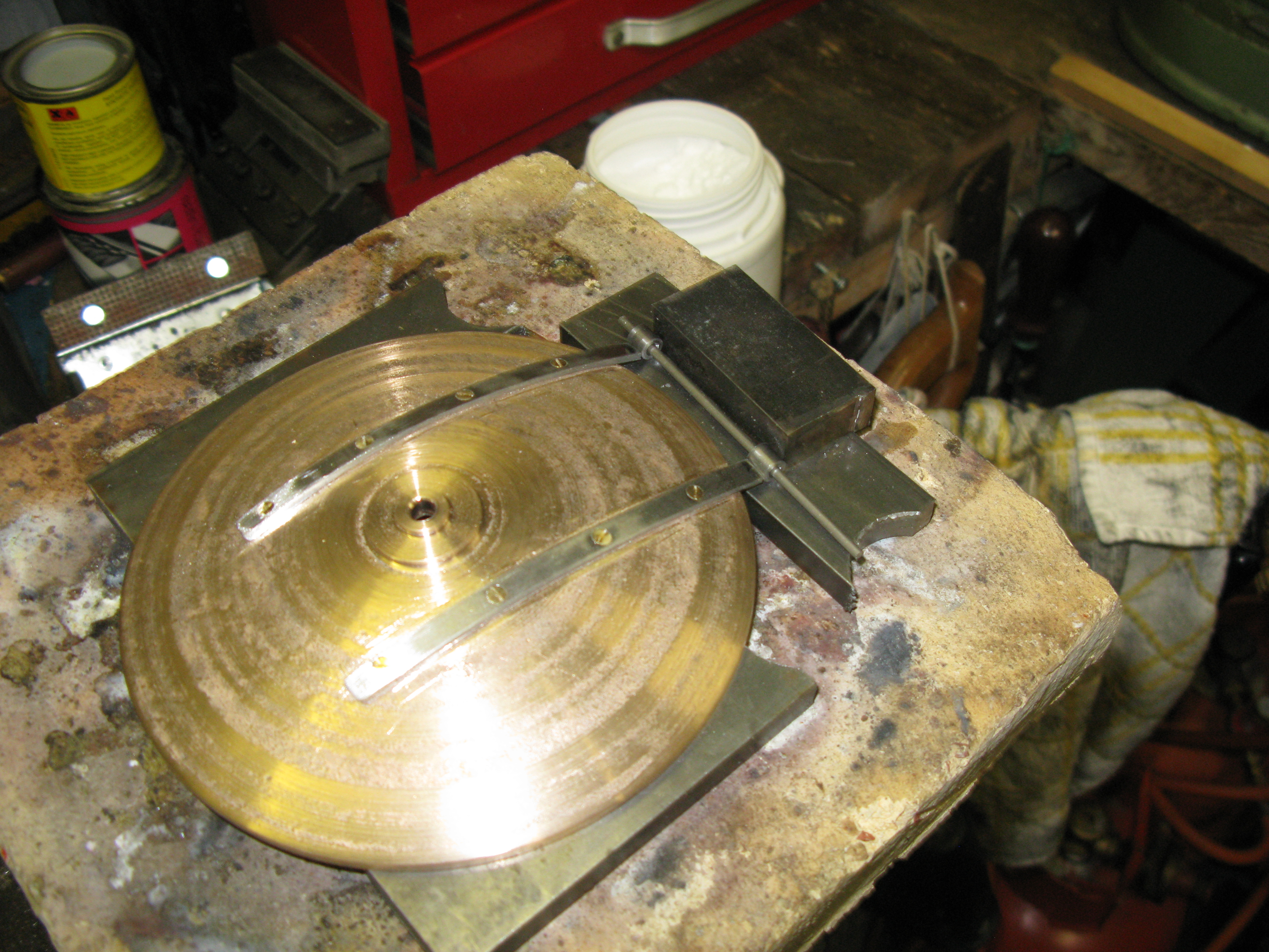
This entailed using the rotary table and to ensure the casting was centred correctly I made a jig piece to fit into the bore and over a central spigot on the table. The clamping arrangement of a single clamp enables one radius and one estraight edge to be machined. The casting is then moved to use the other chimney hole to do the other end radius and other side. The same set up is used to put the radius on between the top of the lip and top of the chimney using a ball end cutter.
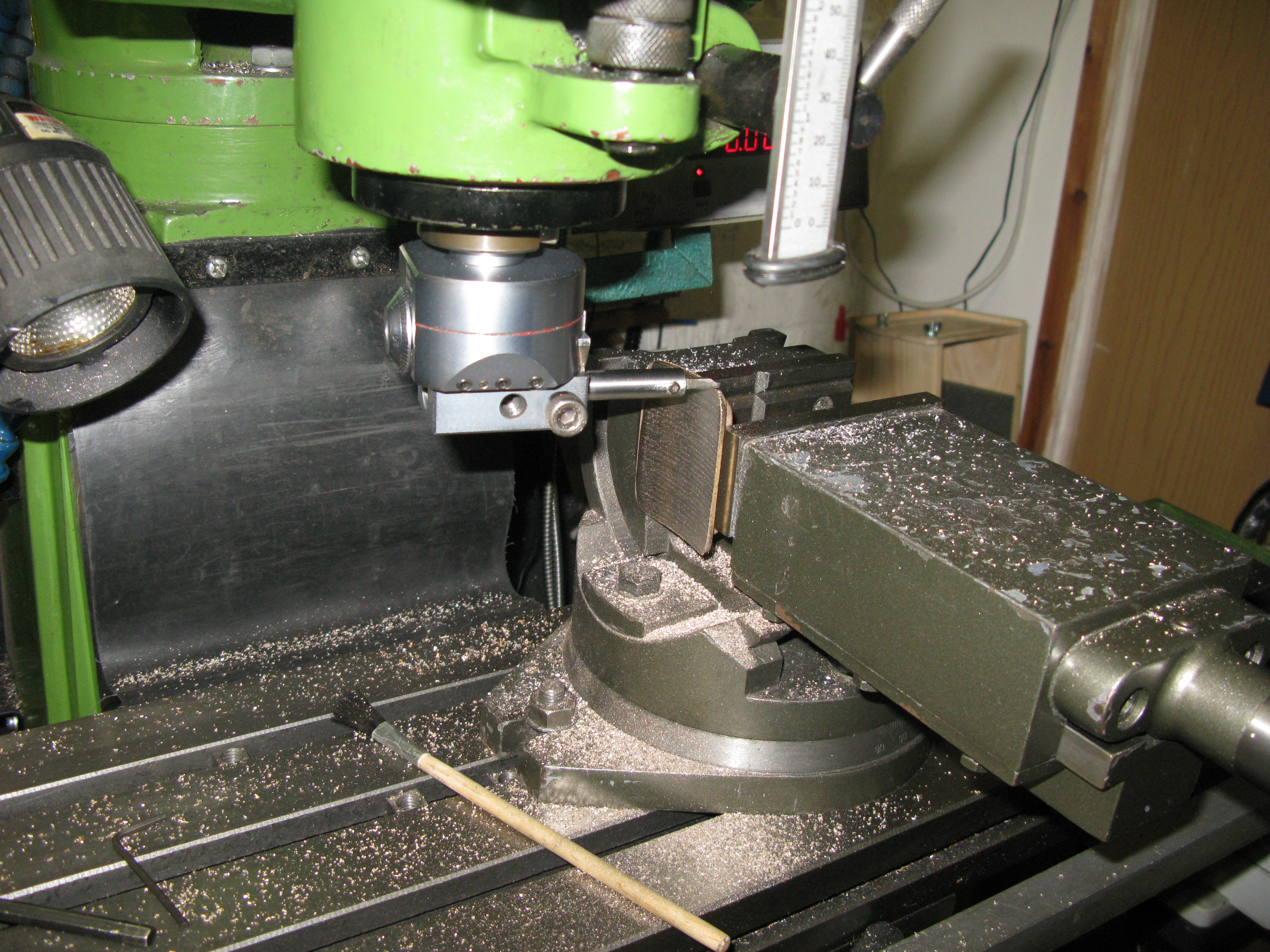
To do the underside of the lip required a different set up. The rotary table was set up on end and this allows the ball end cutter to put in the radius and do one edge. However the cutter had to be held in a drill chuck as the mill chuck fouled the rotary table. The drill chuck gave just enough clearance both up against the face of the table on on the top of the diameter.
The final machining operation was to flycut the smokebox diameter. At this point I found that there was no way the as drawn height of the chimney was going to be achieved as it would cut away much of the bottom of the chimney and would be undersize on width by quite a lot. As I had only taken a skimming cut off the top when machining the bores clearly the casting was never going to allow the as drawn hight to be attained. The drawings cover so many engines I wondered if the casting I had been supplied with was in fact the correct one for the A1. Anyway I decided to press on with what I had and machined the radius to what I thought gave a reasonable looking chimney.
The flycutting of the chimney had to be done on two stages as the overall length of the chimney is 4″ and my mill quill movement is 3″. The boring bar was set at the correct radius for the smokebox and the table moved forward to get the required depth of cut.
The casting was set square in the vice using the top chimney surface as the reference having previously set the vice square on the mill table. The flycut was then taken to the depth of quill movement and then the casting turned throug 90 degrees, set square again and the other end cut.
A lot of cleaning up with a hand file followed to get the radii blending from the base up to the lip.
There is no fixing detail on the drawings for the chimney so I looked at a nunber of photos of the full size and determined that there were 12 equally spaced fixing bolts as far as I could see. I used 8BA (small head) fixings matching the superheater access covers. The holes were marked out on the chimney and drilled then the smokebox jig drilled having clamped the chimney in place and using the same copper tube gauge in a bore to align the casting over the holes in the smokebox.
On a whim I decided to see how the smoke box and boiler aligned on the frames and discovered that my boiler is 3/8″ too long! Now this does’nt seem much but what it does mean is the fixings for the superheater covers at the ends near the rear of the smokebox now interfere with the boiler sliding into the smokebox. So nine fixings have to be removed and then the screws shortened so they do not protrude into the smokebox and then fixed in place with Loctite. There is also a knock on effect for the snifter valve as the hole for this is now too near the back as the header is now further forward in the smokebox. I will have to overcome this problem later.
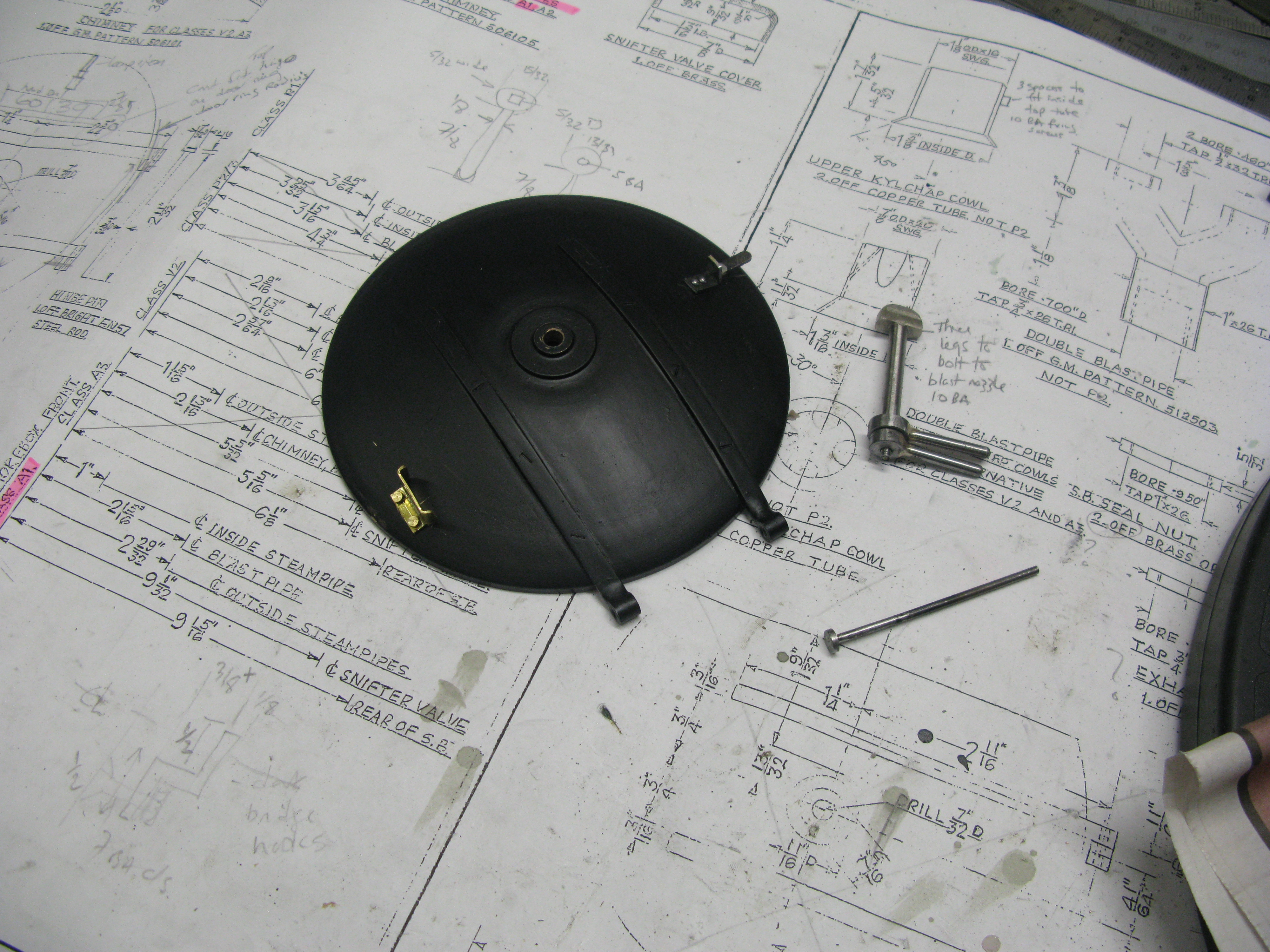
The bridge for the smokebox door dart is drawn as a bolted together part. Two 3/8″ x 1/8″ bars are seperated at their ends by 1/2″ x 1/4″ spacers and bolts put through all three parts. The end also has a hole through it at right angles to presumeably allow it to be bolted to the front ring but there was no drawing detail to show how it was mounted.
I was not overjoyed with the prospect of a fixed bridge as that was going to be inconvenient for cleaning out the smokebox after a run so I decided to have my bridge sit in a Z bracket at each end which enables the bridge to simply be lifted out. I saw no purpose in having the bridge a bolted assmbly so silver soldered the spacers in the ends.
The Z brackets are bolted to the inside of the ring using two c/s set screws. These are finished flush to ensure no leakage occurs with the door closed.
Jig drilling the Z brackets in place
The Z brackets were made simply by milling a piece of bar with two slots 180 opposite and offset.
The bridge sitting in the brackets …. sorry about poor focus.
The dart is made from 9/16″ round bar. It was first turned down to allow a 5 BA thread to be put on the end and then the rest of the bar turned down to 7/32″ diamter to slide smoothely into the door hole. The bar was then parted off leaving enough to make the dart head which was done by reversing the work in the chuck and using a ball turning device to put on the 9/32″ radius.
Finally the dart was moved to the dividing head on the mill and the dart head machined down flat to 7/32″ thick. The dart was then turned around and the square milled on the shaft for the turning handle to fit onto.
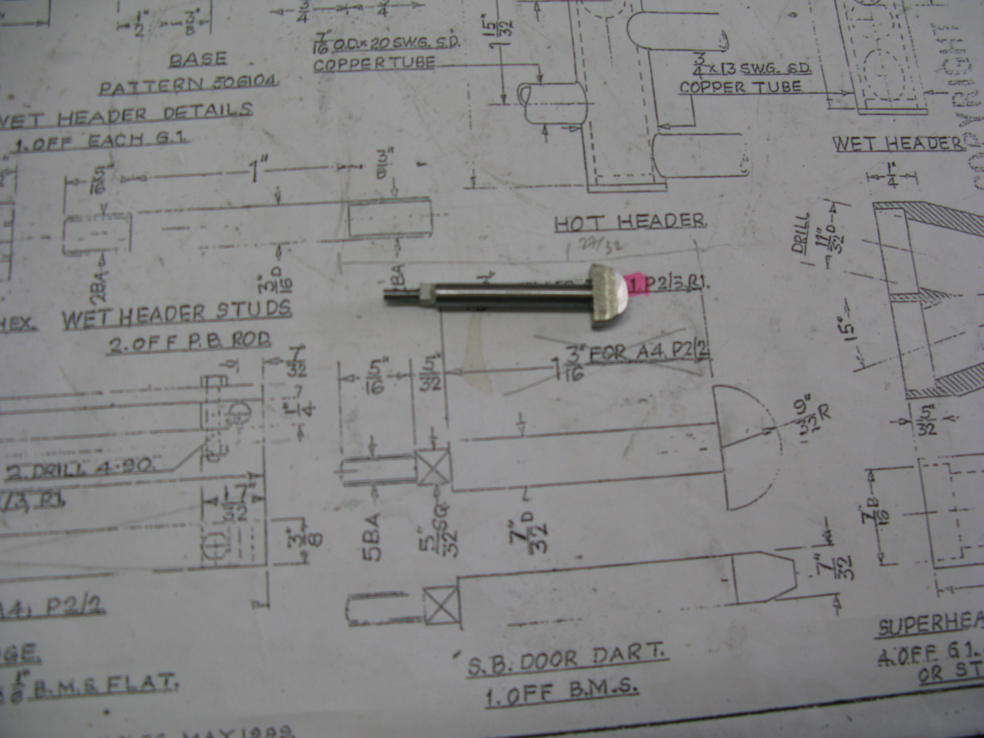
The finished dart.
With the door on and the bridge in place the dart was checked to be operational only to find the dart was 5/32″ too short! Yes, it was made to the as drawn length.
I had two options make a new dart or modify the bridge so it sat 5/32″ forward. I chose the latter as it was easier and quicker just to mill a 5/32″ step at each end. The knock on effect of this was the the bridge was now a sloppy fit in the Z brackets and if the dart was not correctly aligned it would just push the bridge back in the Z brackets and never enter the bridge. To overcome this I simply glued a 1/8″ spacer to the rear of the bridge to reduce the sloppy fit. The door and dart now work perfectly.
The door handles have one with the square in the centre to work the dart and the other a 5 BA tapped hole to lock the door firmly against the smokebox door ring. There are no details drawn for them so I just scaled the length of the handles of a GA drawing. These were drawn as parallel handles but I put a very slight taper on mine. The handles are silver soldered into the bosses at a slight forward angle. Again no dimensional detail drawn.
There is a small step on the smokebox door. There is no detail of this item so I judged the size from photos of full size and it approximate position on the door. The step is made from brass sheet and bent appropriately. It is fixed to the door by two 10 BA screws into tapped holes.
At the top of the door there is a lamp iron. Again no drawn detail so back to the full size photos to estimate its size and position. It is held onto the door with a couple of 1/16″ RH rivets held in place with loctite.
Step and lamp iron added …… hand bar, shed ID and number still to add.
Blast pipe
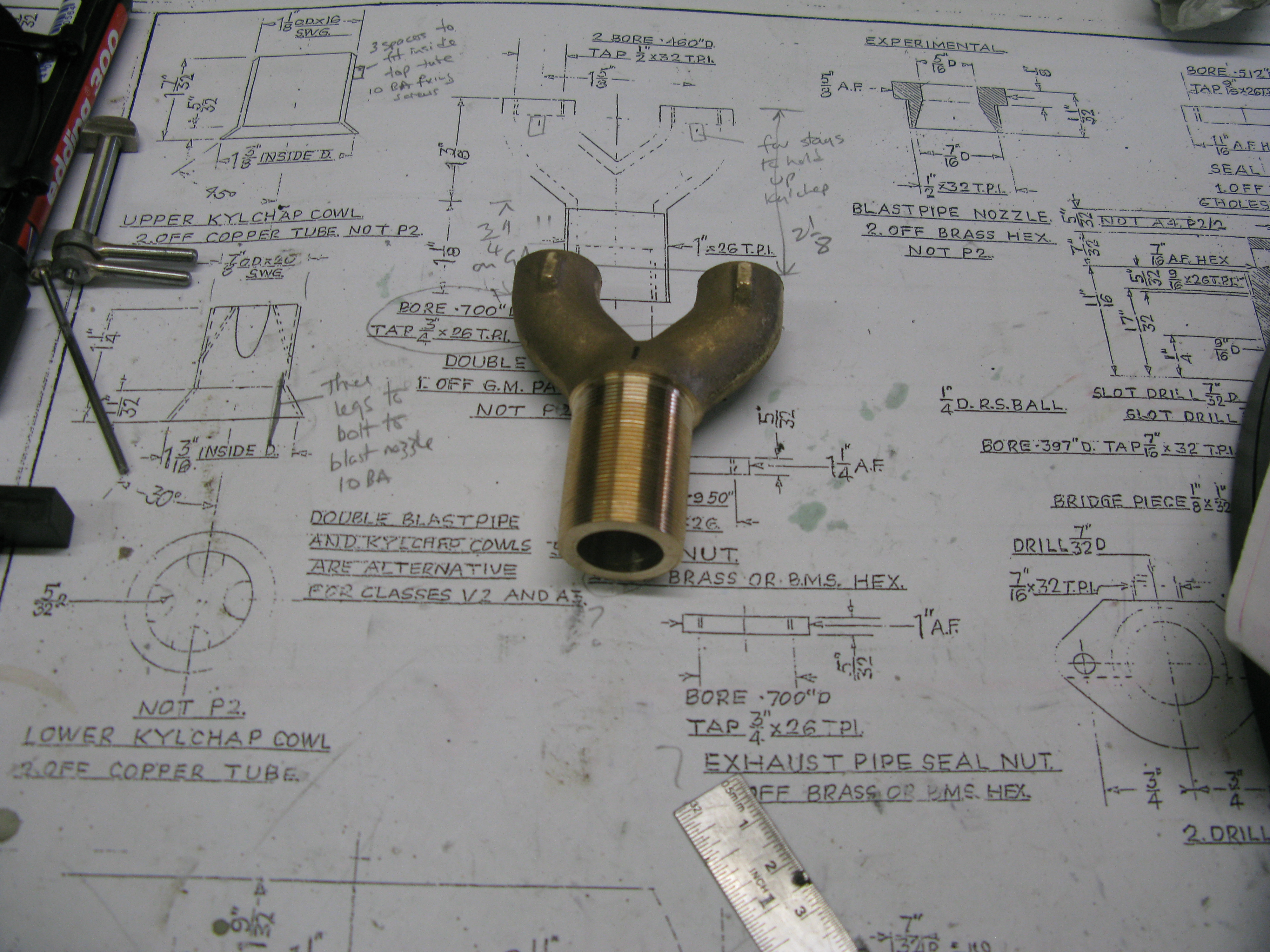
The twin blast pipe is a gun metal casting. Looking at the drawing anomalies were present. The overall length of the blast pipe part as drawn was totally different to that drawn on the cross section GA of the smoke box. It would appear that the GA is correct for the A1 and perhaps the part as drawn might be for a different engine. Also the part drawing has an internal thread at the bottom of the blast pipe. No idea why as it is not used on the GA drawing.
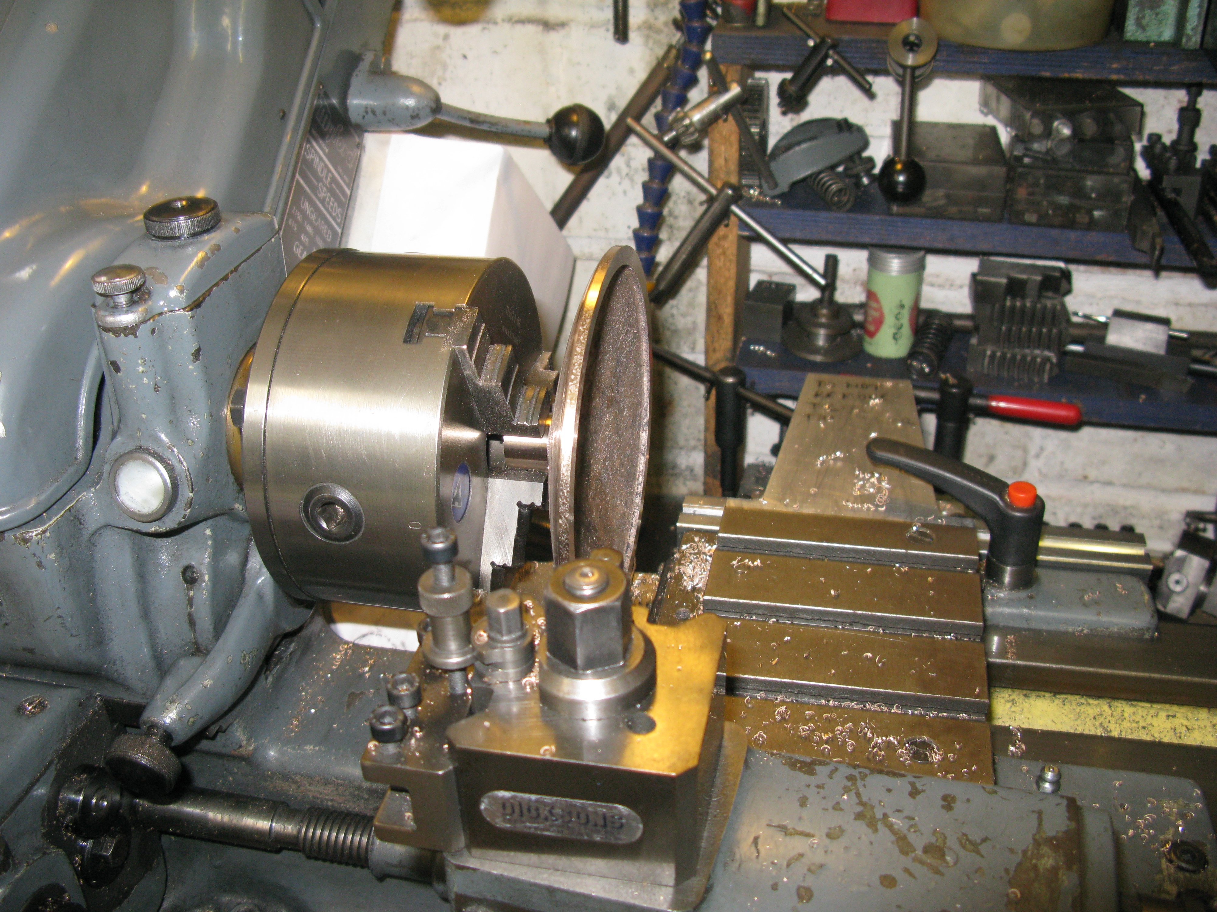
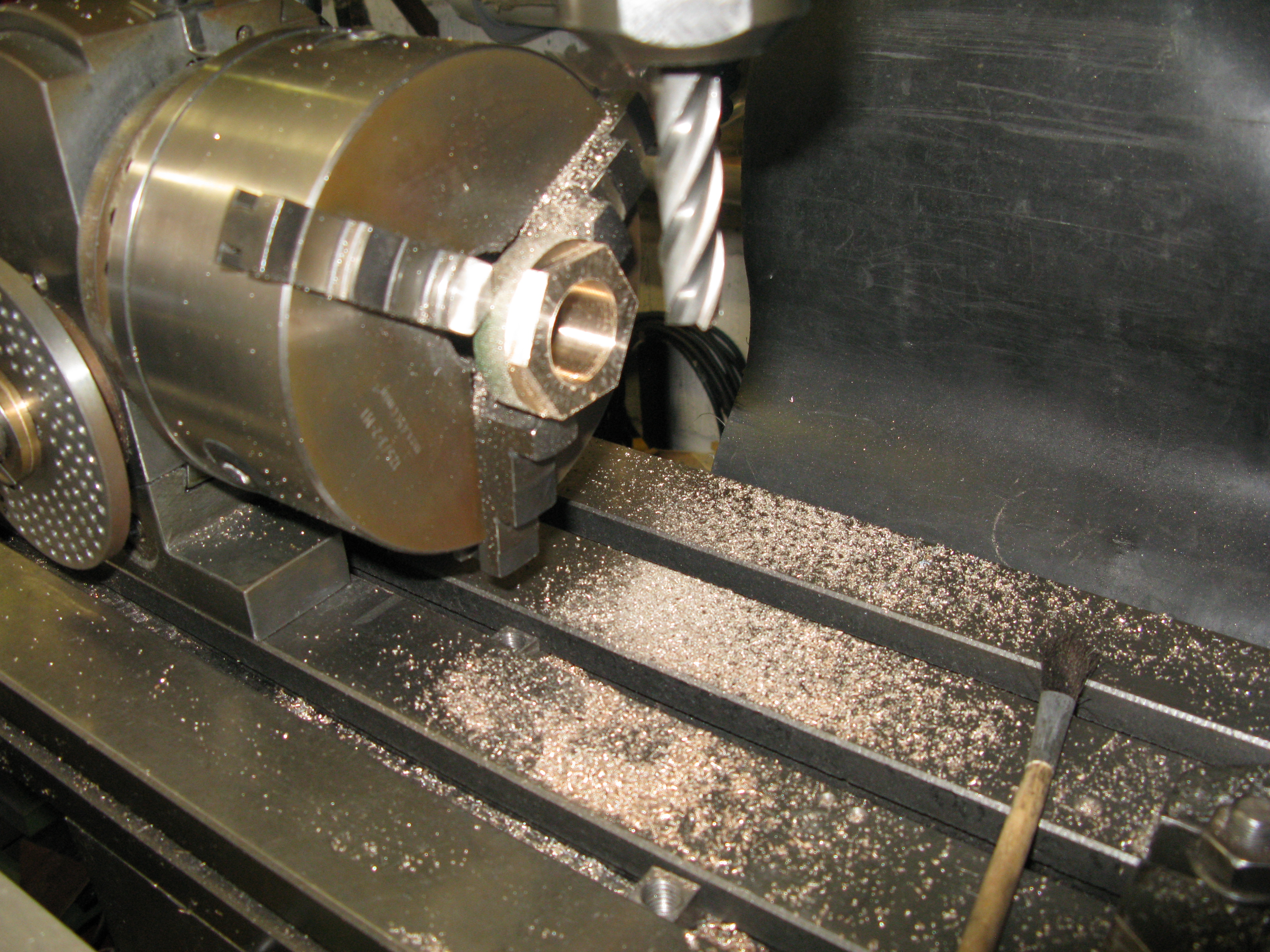
But onto machining. It is an awkward casting to hold but to turn the 1″ x 26 tpi thread on the bottom of the blast pipe the set up on the lathe is shown in the photo below.
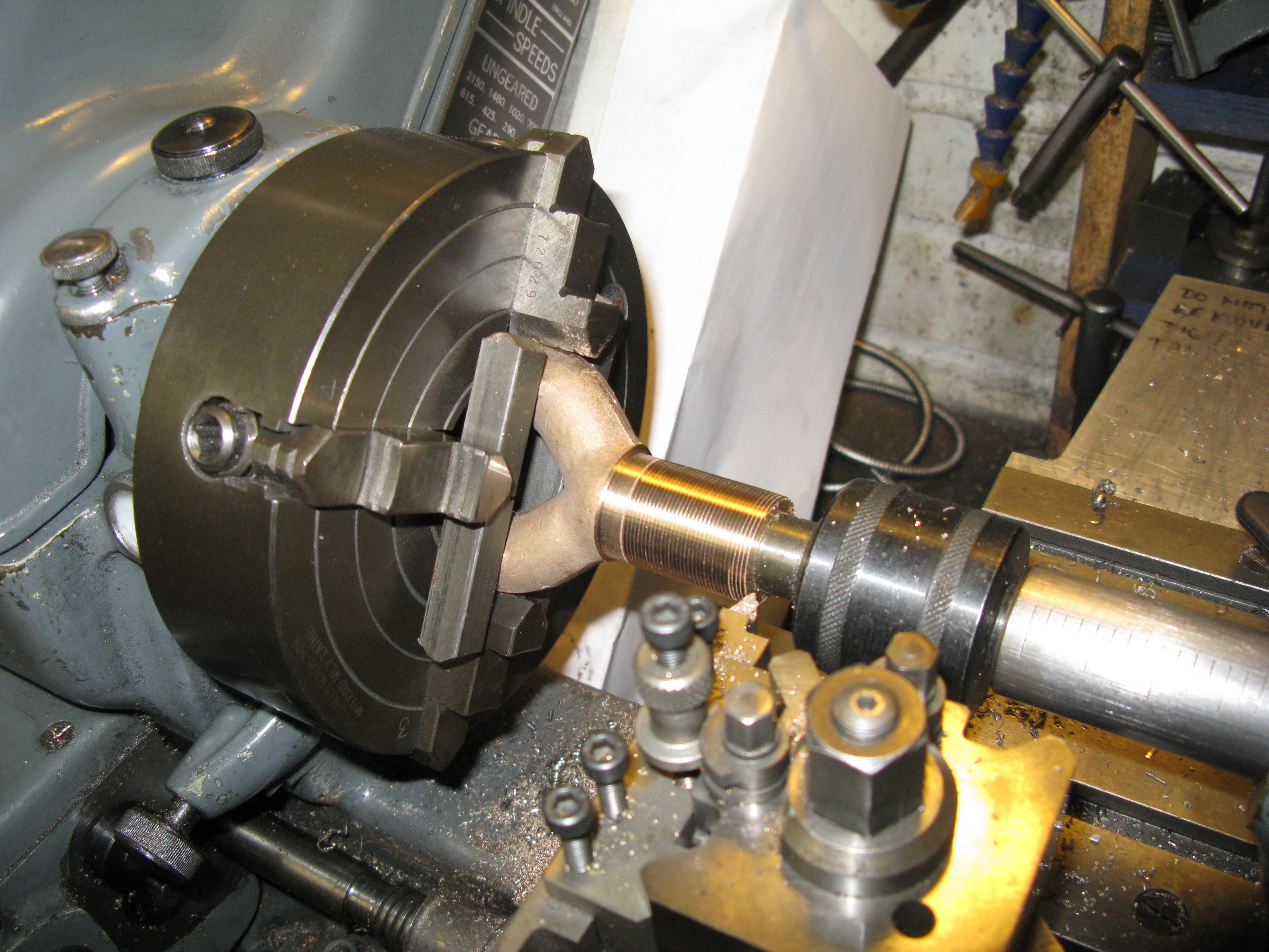
It took a little time to get it right as first of all I had to get a round hole in the bottom of the pipe for the revolving centre to locate in. This was done with care and a boring bar but only after much tweaking of the chuck to get the cast bottom part to run as parallel as I could manage. Once I had the clean hole and the centre set up the thread could be screwcut. I have to admit that the part was on and off the lathe three times to check that the thread would fit into the K exhaust. Each time it had to be recentred to run true. But all was well in the end with the pipe screwing into the K exhaust freely not to tight but no slop.
The next task was to machine the two top parts and here came another problem. The casting was not very good as the cores used to make the holes when cast were off centre and were too large to enable the machined holes to clean up to the correct size in order to tal 1/2″ x 32 tpi. Also the distance apart of the two pipes was such that it was impossible to get the centres of the pipes central on the casting as they have to be equidistant over the centre line of the bottom pipe in order to align with the kylchap cowles and chimney.
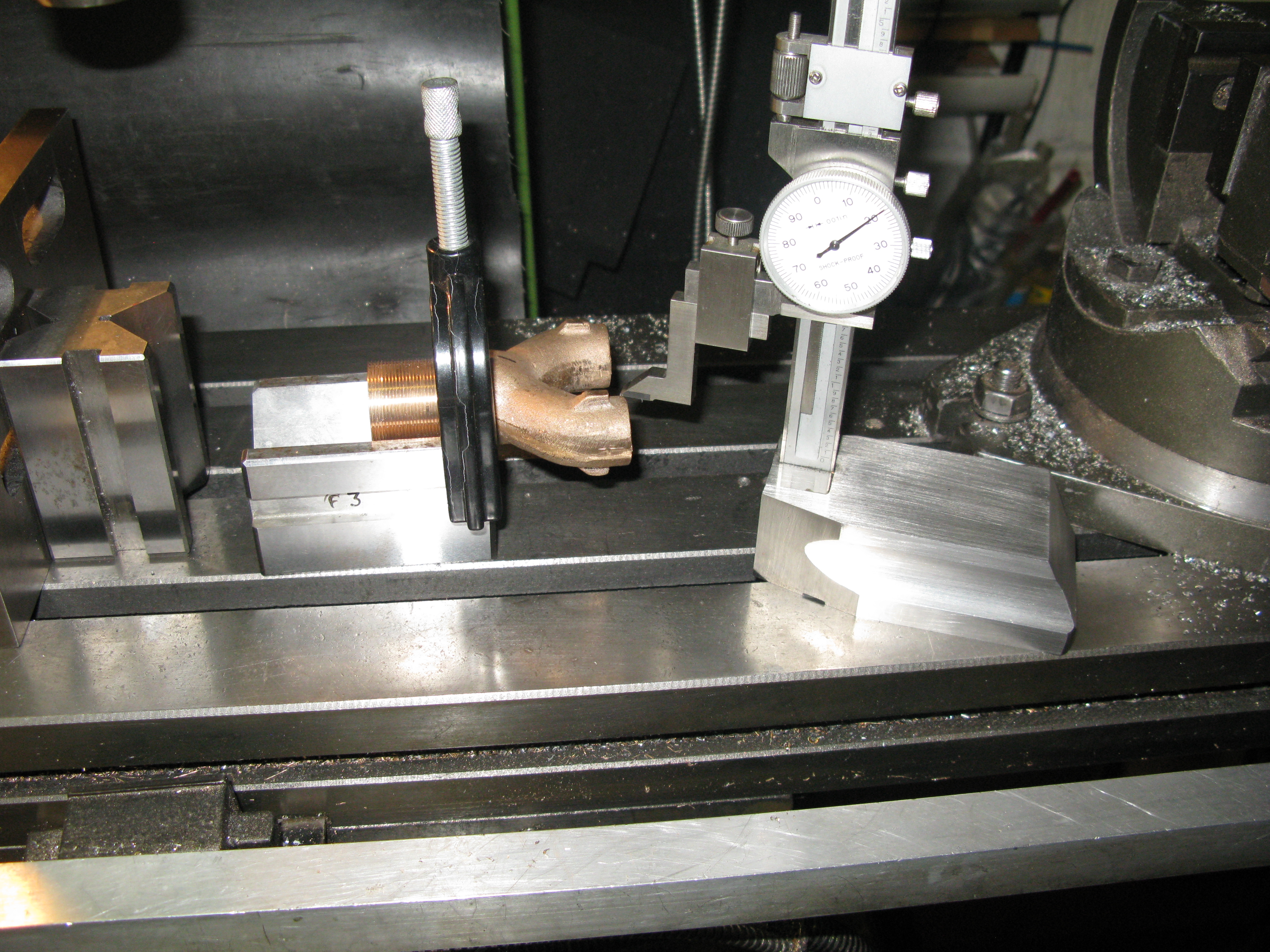
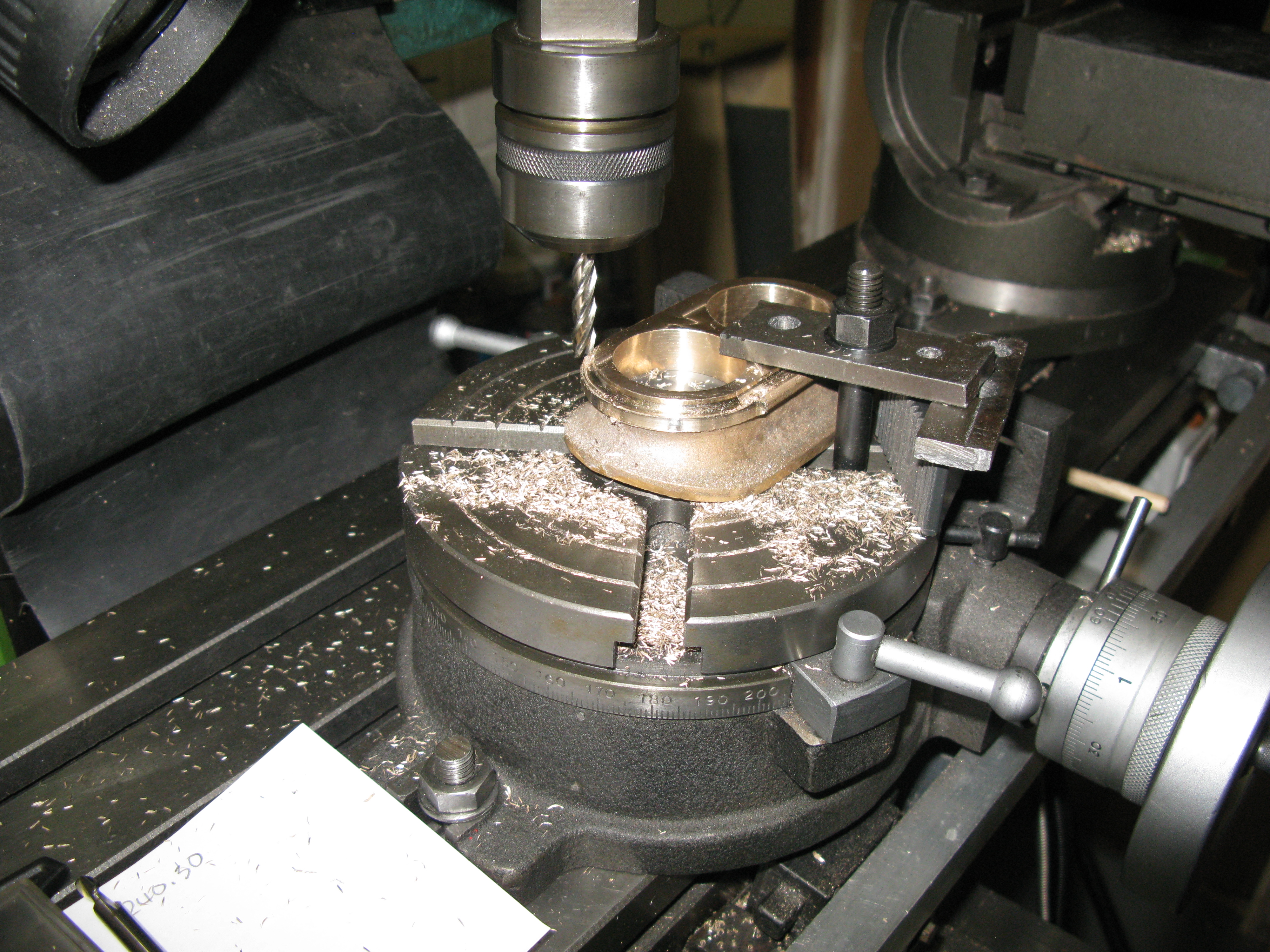
The centre line of the holes was marked on the top of the casting using the set up illustrated above. The machining set up is shown below.
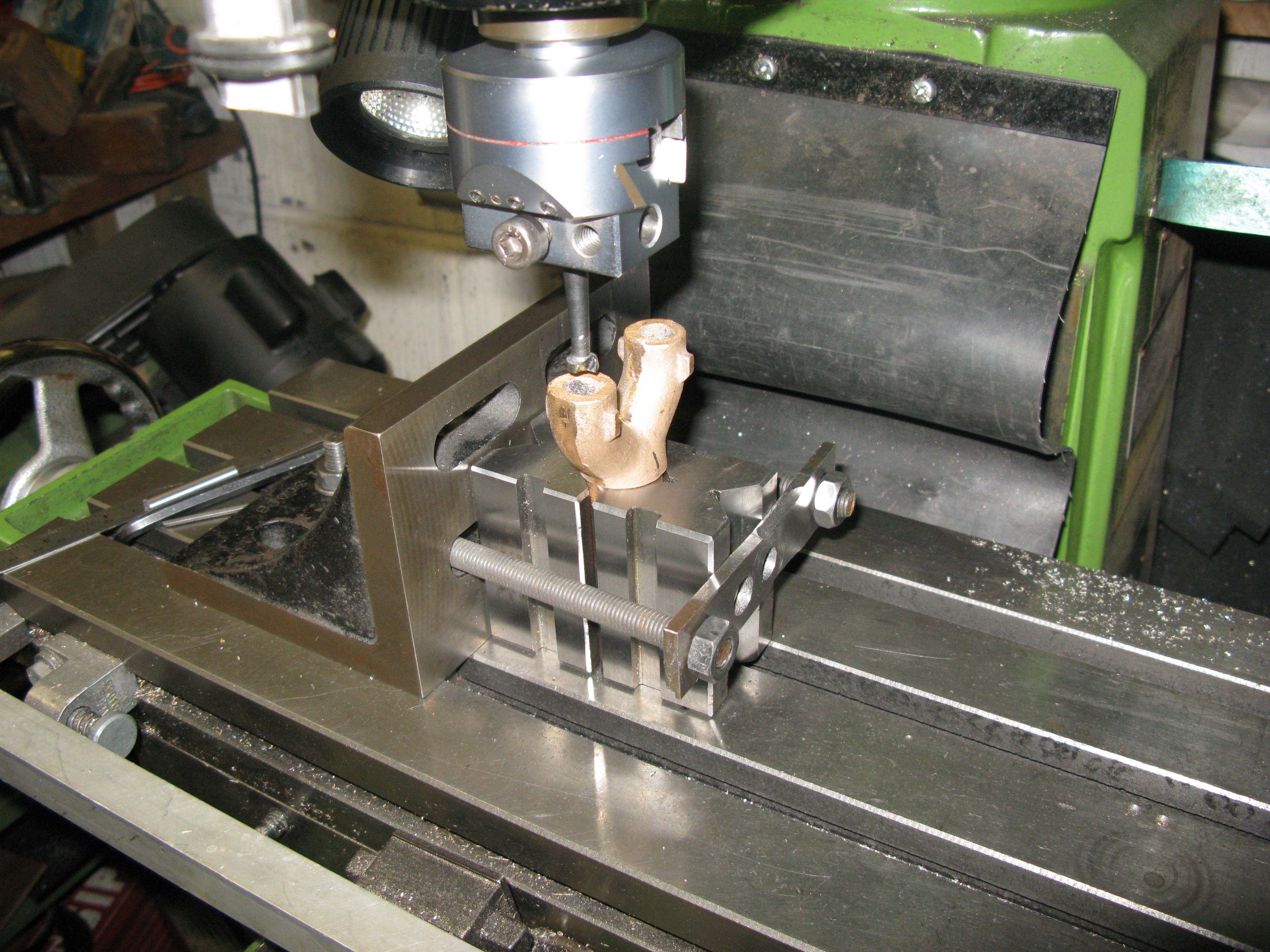
The two V blocks avoid damaging the machined thread and hold the work quite firmly for boring the holes.
As said earlier, the holes would not locate centrally in the pipes and were going to be oversize to get the holes cleaned up. This means they will have to be sleeved with a tapped sleeve to take the blast nozzle.
In case anyone wonders what the pips on the sides are for they are there to take stays to hold the kylchap cowles in place. However these are not detailed on the drawings. I will talk about these much later on.
casting machined but not yet cut to length.
The sleeves for the blast nozzles were made from brass turned down to fit the holes drilled and tapped and fitted in place with loctite.
The fixing holes for the lower kylchap cowel were drilled and tapped 8 BA in the two pips on each pipe.
The locknut for the blast pipe was made from gunmetal drilled and bored and screwcut 1″ x 26 tpi. The chuck was then transfered to the dividing head and a hexagonal machined to accept a spanner.
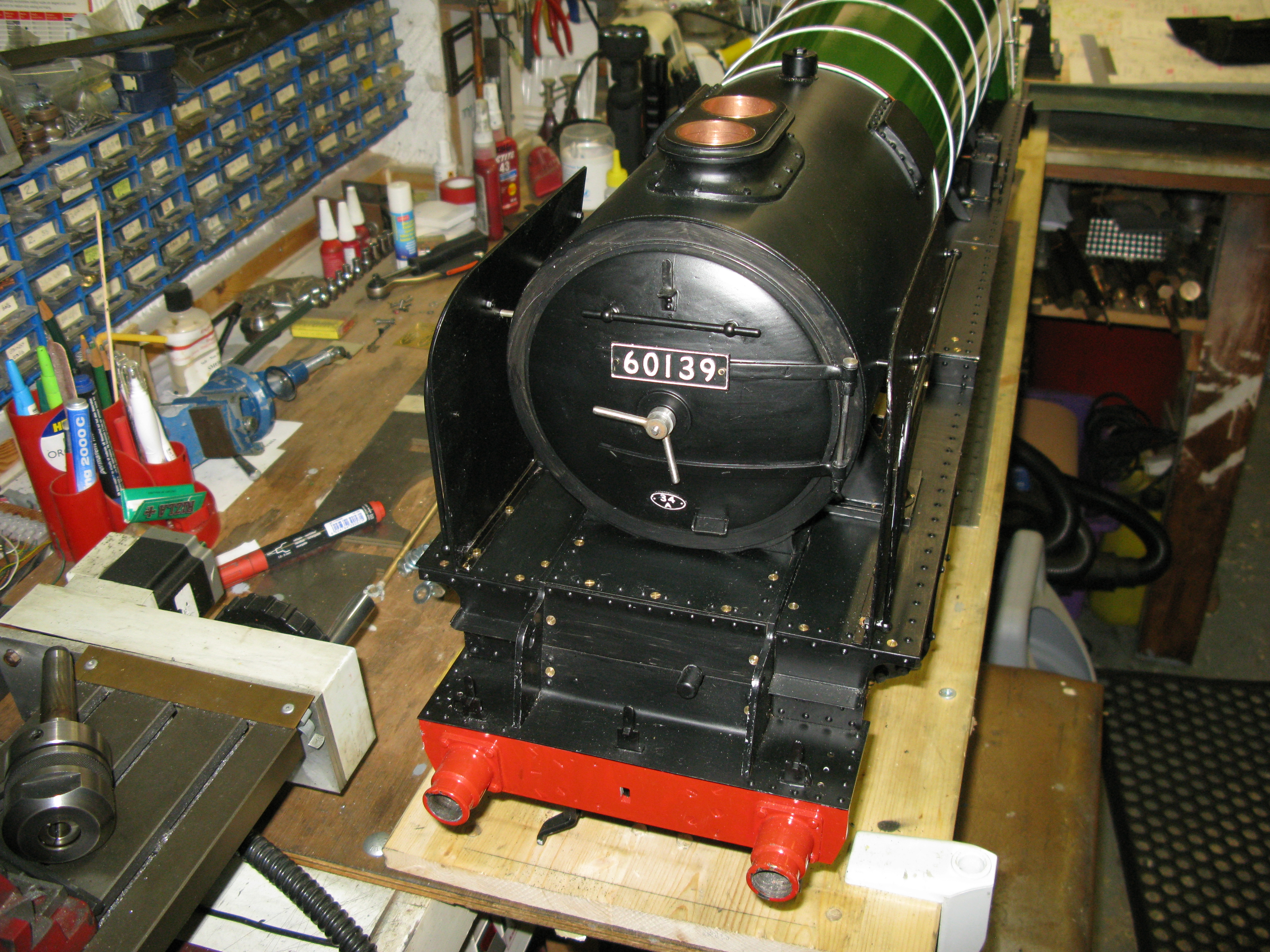
The sealing washer that fits between the locknut and the smoke box was also made from a piece of gun metal filed to give the radius of the smoke boss and then bored to give 1″ clearance and turned to a thickness that just left an edge at the thinest side. This will when fitted be sealed underneath with high temperature silicon sealant and the locknut tightened down. Lastly the blast pipe thread was shortened to the correct length and the blast pipe painted.
Trial fit of the blast pipe
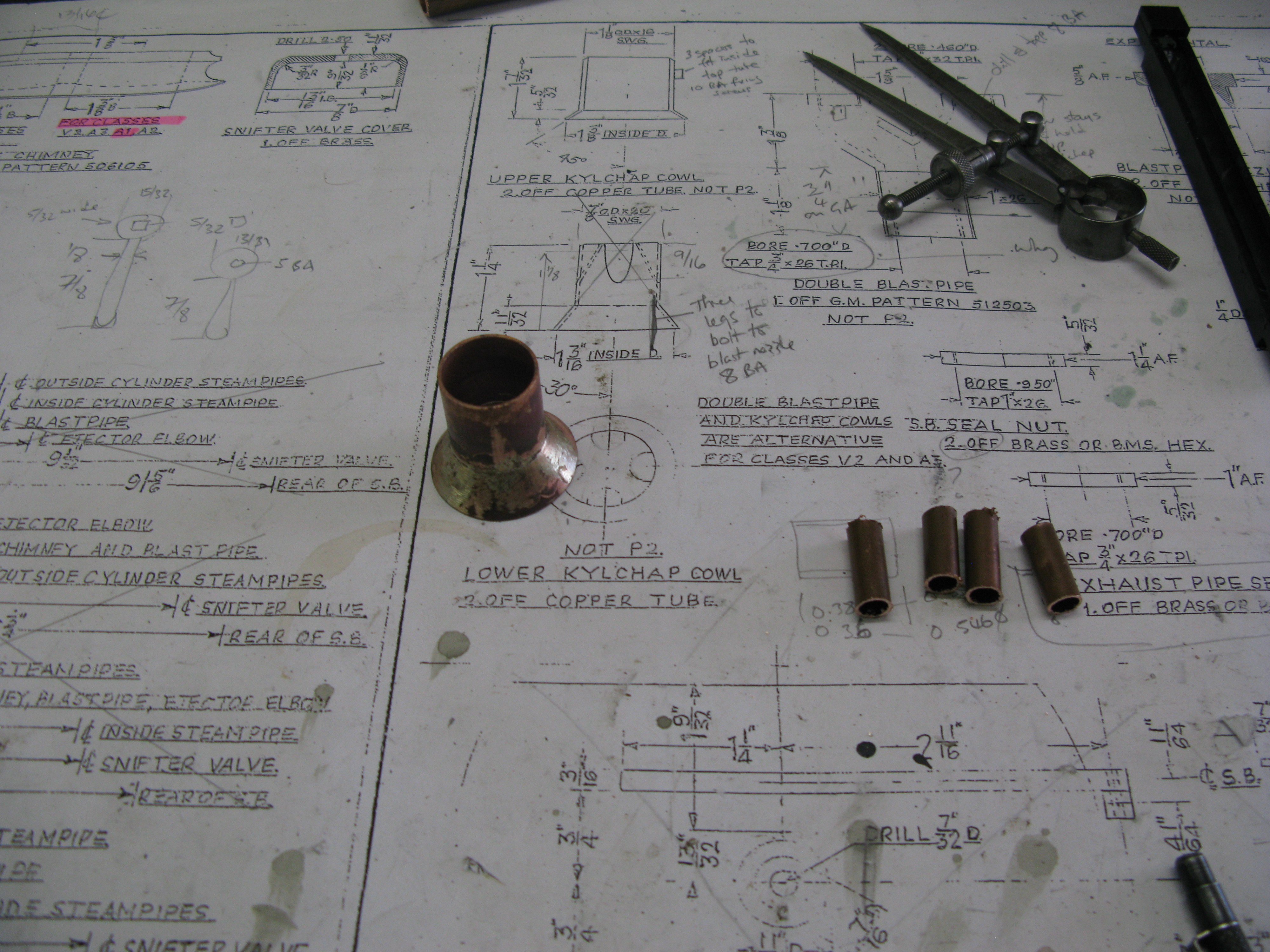
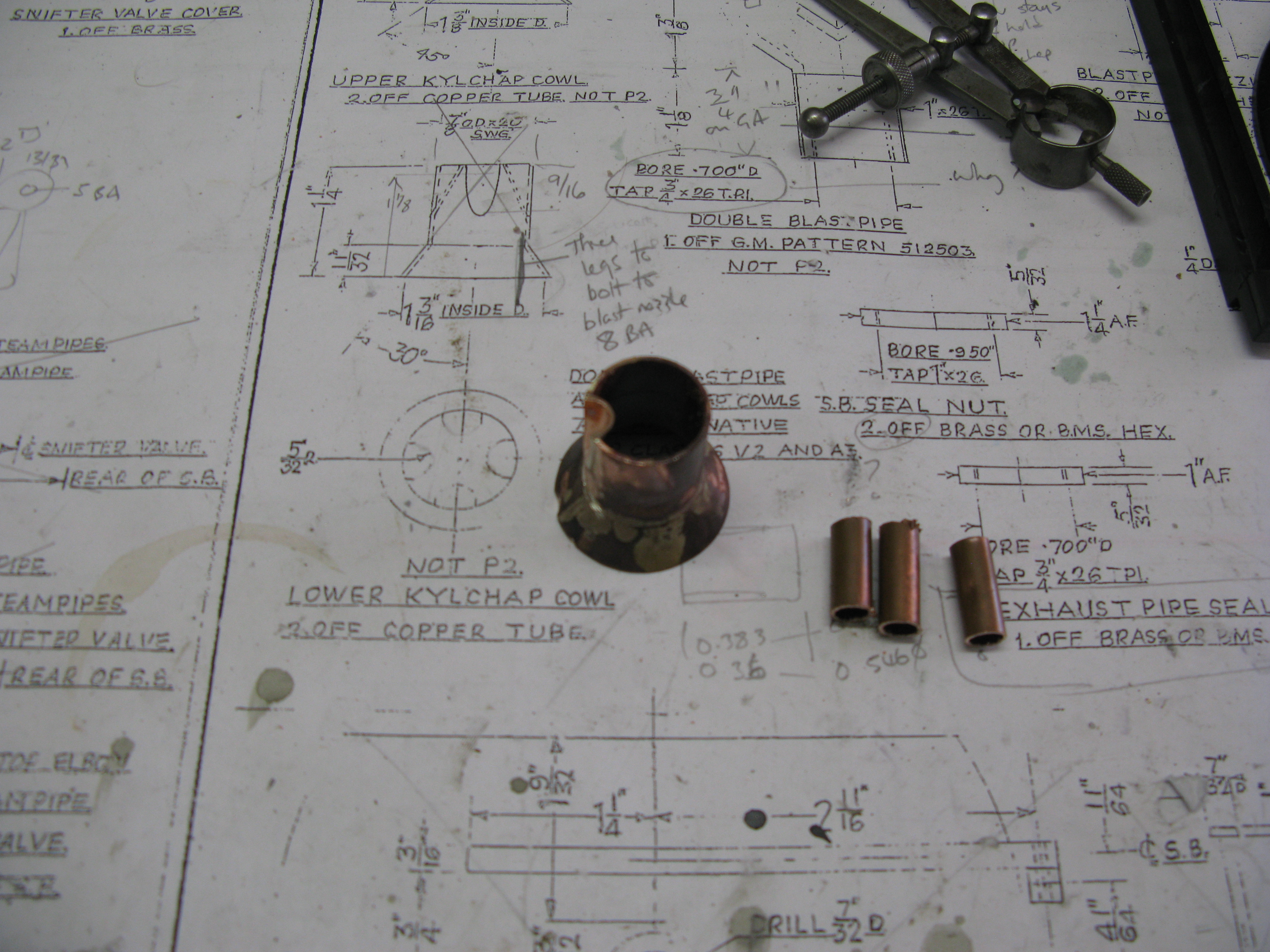
The lower kylchap cowl was next on the to do list. This is fabricated from a piece of 7/8″ OD copper pipe with four pieces of 5/16″ OD copper pipe let at an angle to form the venturi and a petticote skirt silver soldered to the bottom.
The first job was to make the skirt. The developed 2D shape for the skirt is from a cone frustrom. This was scribed onto 20g PB sheet and cut out. It is then carefully bent around the 7/8″ copper pipe to form the skirt and silver soldered in place.
A round 5/16″ dia. groove is then filed in the tube at and angle so the centre line of the 5/16″ pipe aligns with the edge of the tube. A piece of 5/16″ pipe is then silver soldered in the groove and cut back to form the semi circular hollow.
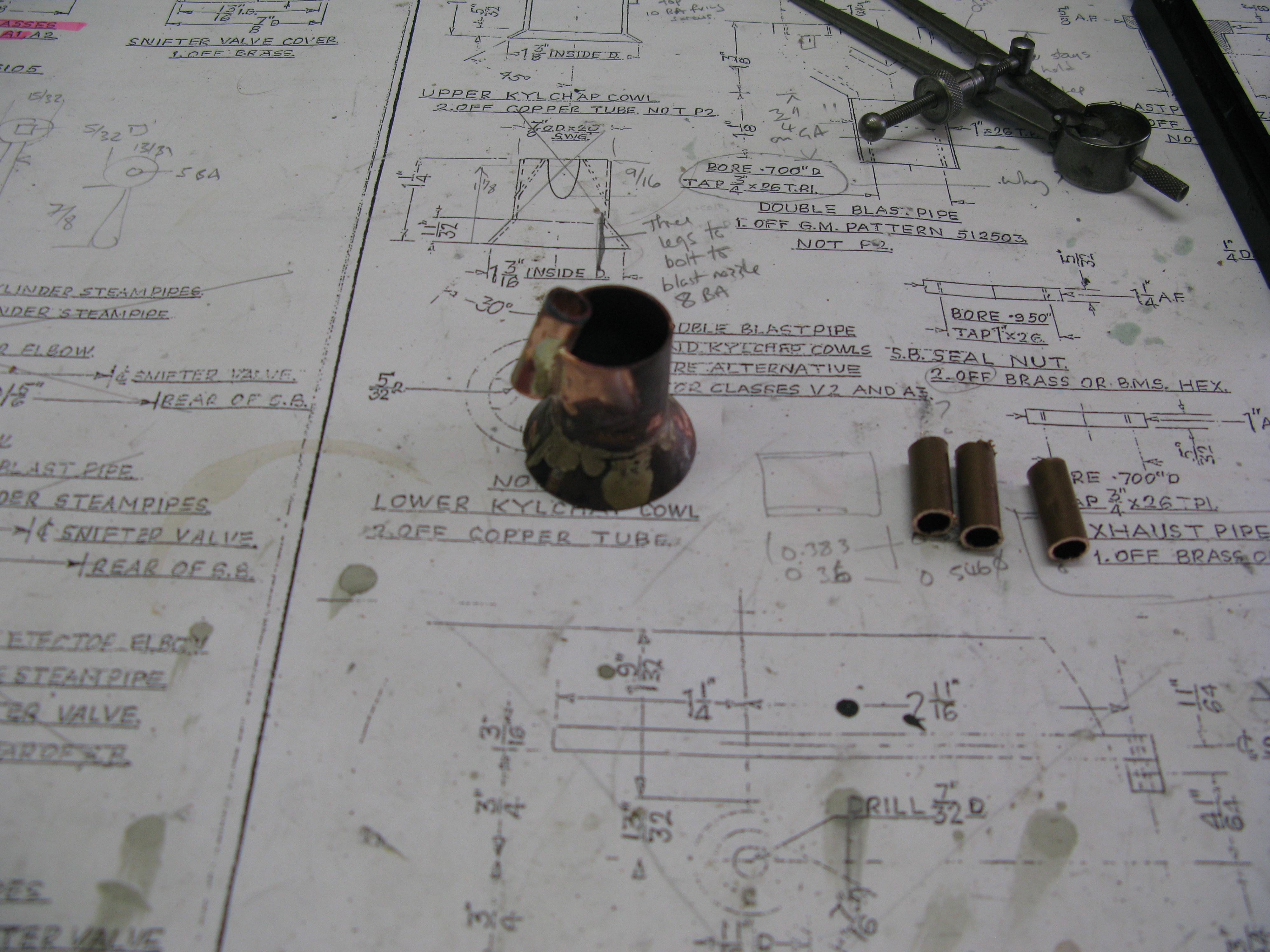
The remaining three pipes are then individually done one at a time as to do otherwise risks the main tube becoming too flimsy.

A finished lower kylchap cowl.
The middle cowel is simpler as it does not have the semi circular inserts otherwise the skirt is done the same way as desribed above.
A trial assembly of the blast pipe and the next two cowls has been tried having been given a coat or two of paint. The side supports are made from 5/32″ wide brass strip and each support needs to be bent to clear the bottom skirts. The fixings are 8 BA.
Trial assembly of Kylchap cowls
This is a very fiddly job to get the supports bent in such a way as each cowl has to sit centrally over the blast pipe. At this stage this is done by eye. First the bottom two clips are made then the cowl offered up to determin the position of its fixing holes. Next the upper clips are made and fixed to the cowl and then the upper cowl offered up to determin its fixing holes.
As the fixings are 8 BA brass hex head screws with the head inside the cowel they are likely to create interference with the exhaust steam flow making it turbulant. So I soft soldered the heads to the cowel and then ground the heads down as far as I dare to get a smoother exit path for the steam flow.
The final cowel fits into the chimney and it has a skirt as well but at a much shallower angle and longer. However the full size has this cowel shaped as a venturi not a parallel length on top of a skirt. I have to decide which way to adopt. The bottom of this cowl sits on three angled brackets fixed to the cowl beneath it on the full size. On the drawing it relies on the fit in the chimney to stop it falling down. I shall be putting brackets on similar to the full size whichever version I adopt. The advantage of the brackets is that they will help with the eventual alignment in the smokebox.
However the blower ring has to be donew before the final assembly of the kylchap cowles can be done.
There is no drawing for the blower ring, just an indication on a GA cross section that it is 1/8″ pipe around the blast nozzles, so I had to design my own.
The idea was simple, a piece of 1/8″ copper pipe bent into two rings to fit over the blast nozzles. Attach a block for connection to the steam supply and drill a few holes in the rings.
The pipe bent to form the rings around the nozzles – just needs nipping up a bit.
To attache a block to form the connection toi the steam supply I used some 5/16″ square brass and machined the pipe connection on the end 1/4″ x 40 ME and drilled it 3/32″ to a depth of 1/2″. A 1/8″ slot was the milled to the depth of the 3/32″ hole so the 1/8″ pipe would fit in the slot and be central to the 3/32″ hole.

A piece of brass was the cut to fill the slot and the assembly silver soldered together.

The brass bar was then cut off to give the finished assembly and the 3/32″ hole drilled into the copper pipe. A few 0.030″ holes were then drilled around the circles.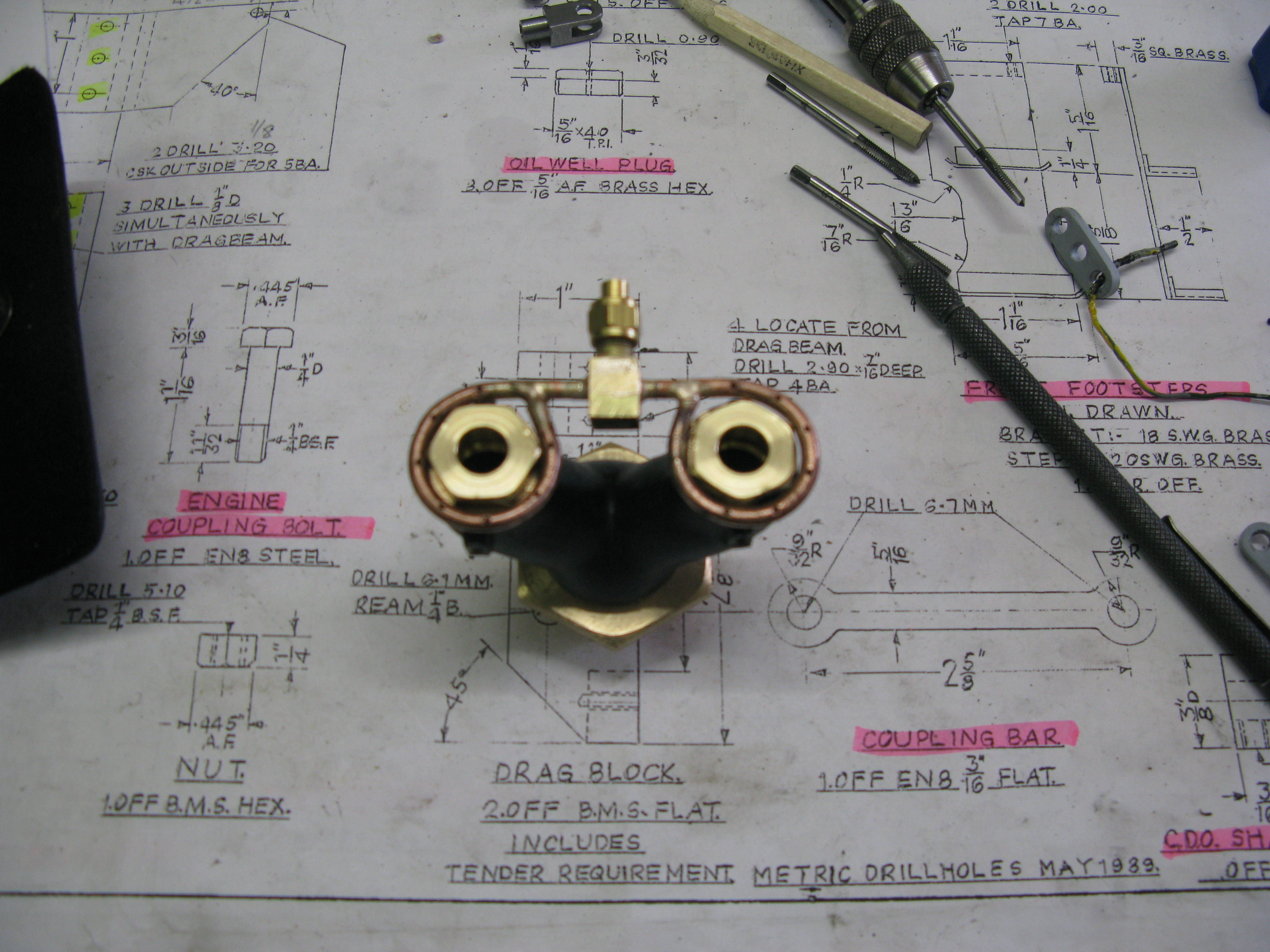
The finished blower
In drilling the blower holes I found on one circle the silver solder had wicked up the pipe which prevented a full circle of holes being drilled in one blower. I thought this was not going to be an operational problem as when raising steam only one chimney is used anyway.
Now the final cowl. I decided to make the top kylchap cowl as drawn, i.e. no taper above the skirt. This I have to admit was partly due to laziness as I did not fancy having to cut out a large piece of 20g sheet to make the taper. and also I was not happy with the fit then being reliant on the top few thou to hold it in place in the chimney casting. So a parallel top part it was to be.
I have mentioned before that I intended whatever shape the top cowl took the skirt had to have brackets which would locate over the top of the next cowl down and centralise the whole assembly. In order to ease the whole assembly when fitting it in the smokebox I also decided to modify the top cowl so it was in two pieces. This would enable the bottom kylchap assembly to be screwed into place and sealed and then the top cowl added afterwards. The modification took the shape of three pieces; the parallel chimney with the bottom turned out to give a 1/32″ recess for 3/8″ into which fits a joining piece having its internal diameter the same as the top chimney and a lip onto which the skirt is silver soldered, and the skirt.
The three piece top cowl – the skirt fitted to the joining piece but not yet silver soldered.
The brackets on the shirt to hold the lower cowl central to the upper cowl were simply made from 20g sheet and three were silver solderd in place.

The cut outs to fit over the lower cowl were centralised by putting the cowl in the lathe chuck and marking off the brackets at 1 1/8″ diameter and then filing the cutouts to get a snug push fit of the lower cowl in place.
The brackets were checked out using a spare piece of 1 1/8″ tube from which the cowls were made and spun in the chuck slowly to veryify all was centralised.
The final fitting ……. The blast pipe assembly and the two lower cowls were screwed in place on top of the shaped washer to match the curvature of the smokebox with high temperature (300 degrees C) silicon sealant underneath and tightened up. The upper cowl was placed on the top ensuring it sat on top of the second cowl seated in the brackest and then the top pipe slid in from the top onto the top cowl and hey presto the whole assembly is solid as a rock.

A completed Kylchap double blast chimney.
Snifting valve
The snifting valve actually fits into the superheater wet header but O have included it here as it is within the smoke box environment.
The valve had to be redesigned from the as drawn version as the position had limited space between the boiler and the pre drilled hole in the smoke box. This meant its diameter had to be reduced.
I chose to make it from 3/8″ AF hex brass with a 3/16″ SS ball as the valve. It has three components to it, the main body screwing into the wet header, the valve portion containg the SS ball and the external cap.
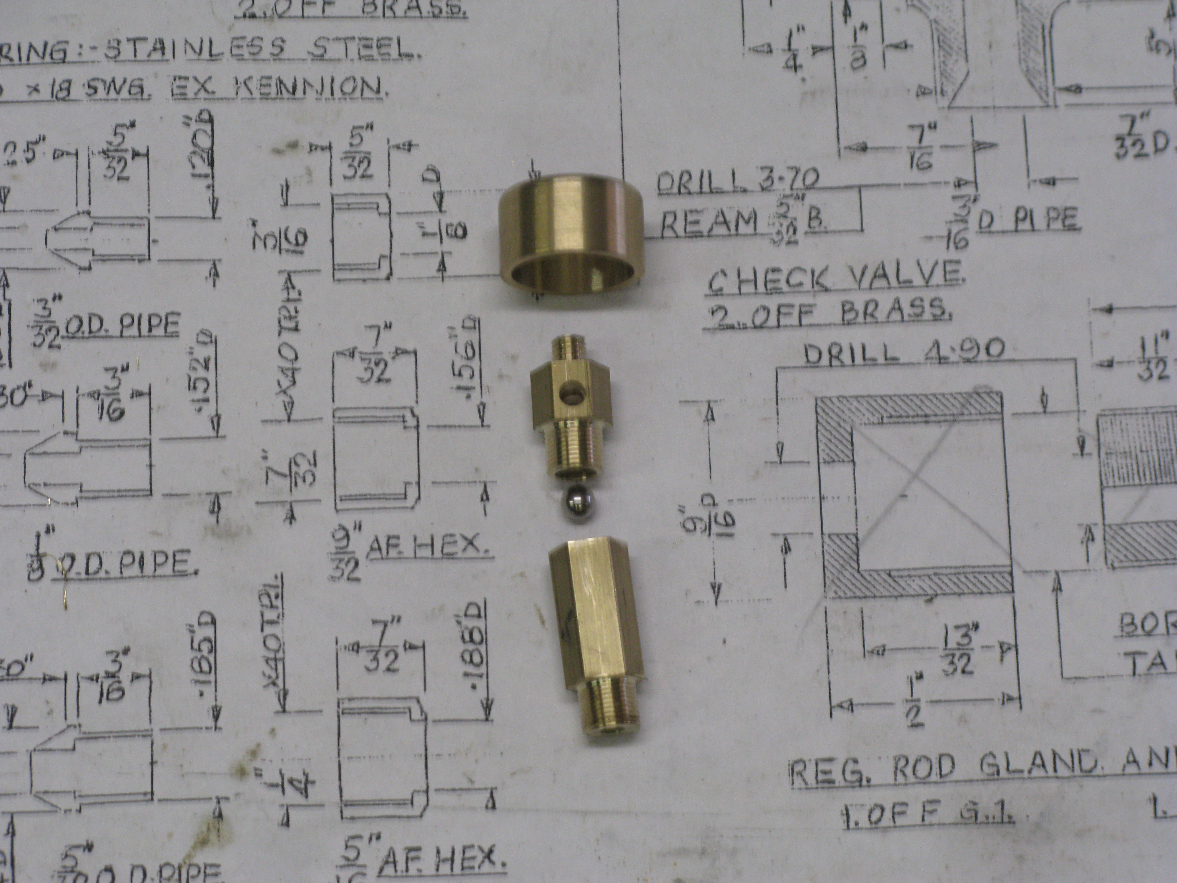
Snifter valve components
The valve once fitted has to be sealed around its periphery where it exits the smoke box. This was done with a brass plate and high temperature silicon sealant.
Smoke deflectors
The smoke deflectors are made from 20g brass with a 3/32″ half round along the top and front edges. The top is laso rounded to a 6″ radius to follow the line of the smokebox when mounted 5/8″ away from the centre line. The bottom has a piece of 1/4″ angle soldered on which bolts to the running board.
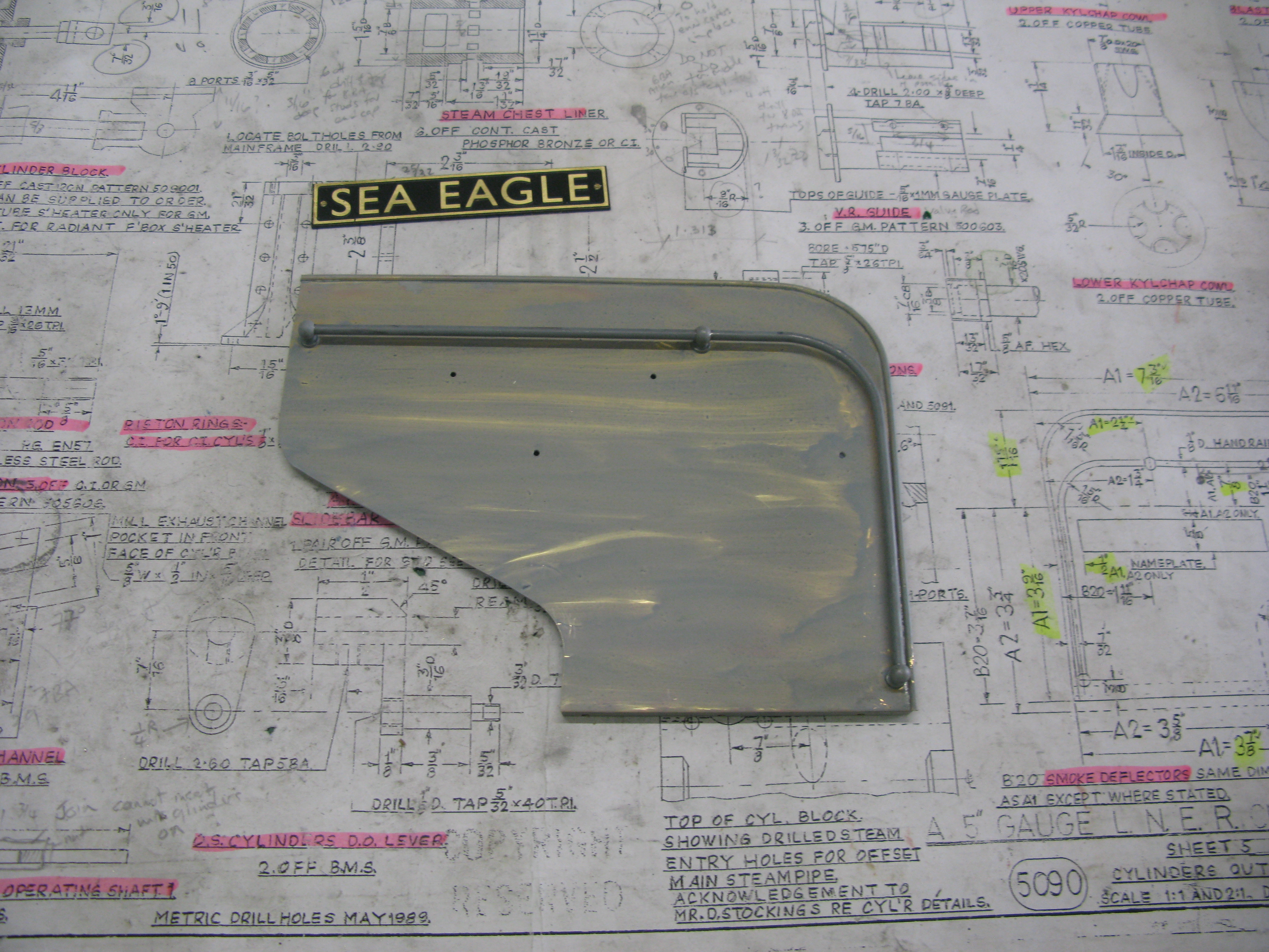
An etched primed smoke deflector
The grab rail has blind end supports and is 1/8″ diameter MS rod. The rail supports are commercial items.
The top two holes that can be seen are for the standoffs that screw in to the smokebox. The standoffs are 1/8″ diameter rod with 10 BA threaded ends giving a 5/8″ spacer.
The bottom two holes are for fixing the name plate.
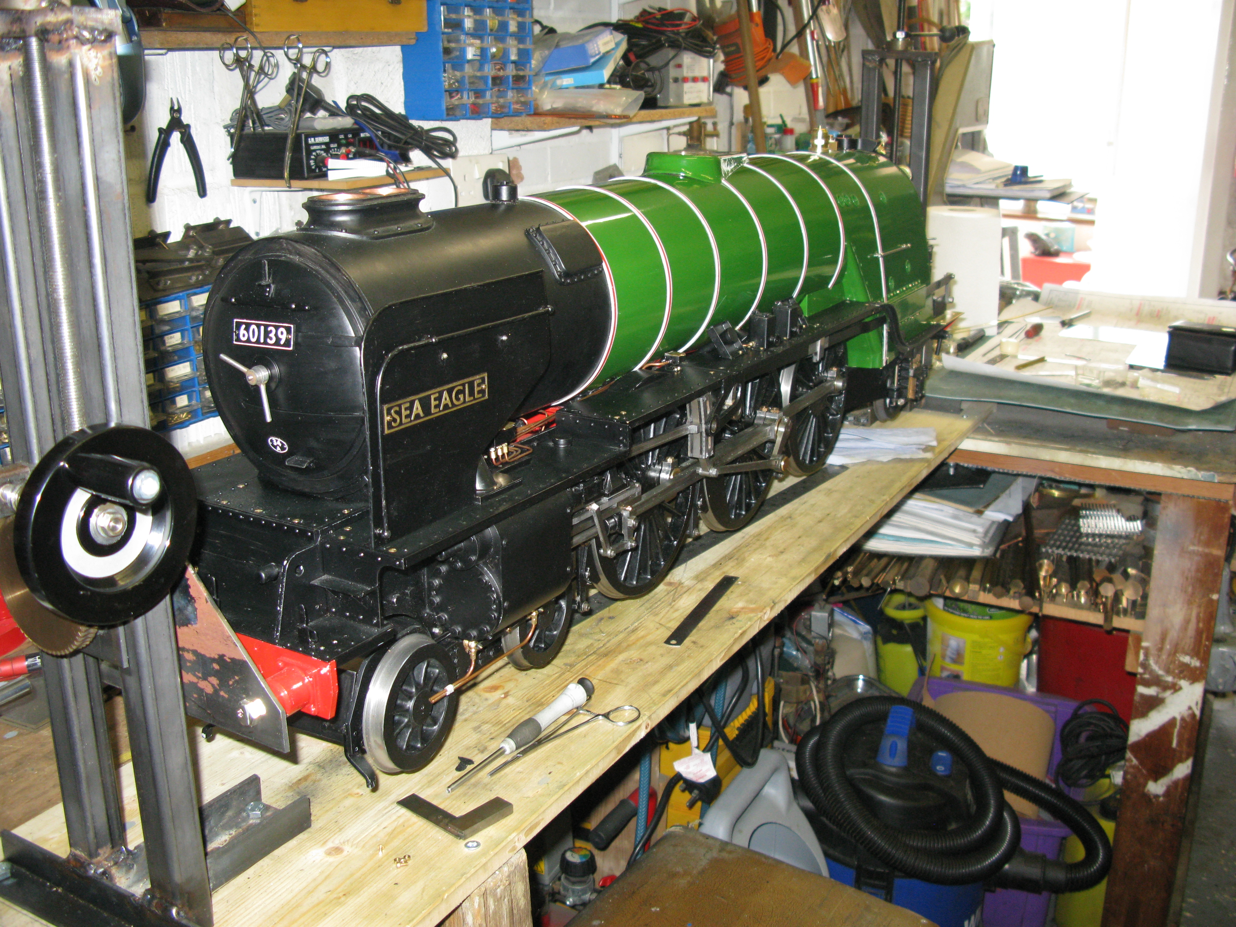
One smoke deflector fitted.
The loco name is chemically etched and they have been done by a model engineering supplier together with the number board, shed plate and manufacture plates. The loco name is bolted in place by 10BA HH screws as is the number plate. The shed plate is epoxy glued in position.
Both deflectors fitted.
