Although work on the smoke box is not finished, I await material, I decided to make a start on the braking system.
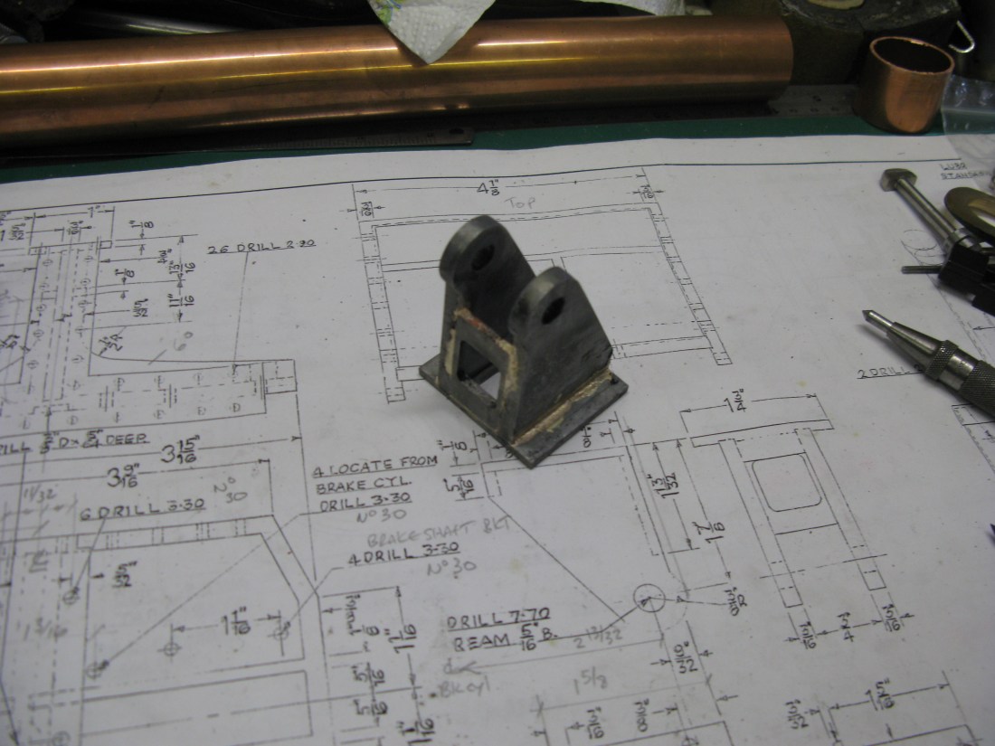
The steam brake is the first job. It is made from two castings, the main body and a cap. The body needs boring out to form the cylinder and the base, which is a square, needs machining flat.

Maching the base square was done on the mill with the work in the dividing head.
The boss at the side is for the steam entry and is drilled and tapped 7/32″ x 40 ME
The cap is just a straight forward turning job.
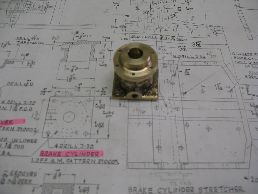
Once turned it is put in the dividing head (mounted vertically) to drill the six fixing holes for 7 BA (tapping size) which in turn are used to jig drill the base for tapping. The cap holes are then opened out to 7 BA clearance.
The piston is made from brass and has two ring slots.

Its stem is drilled 5/16″ to accept the connecting rod which is held in place by a pin at the top.
The connecting rod has a ball connection at the top with a 5/32″ hole through for the connecting pin and a boss at the bottom also drilled for a 5/32″ pin to fit into the operating lever. However the as drawn piston shows the pin hole centre line going through the piston bottom edge! clearly not the best place for it so I moved the centre line down so the pin clears the underside of the piston.
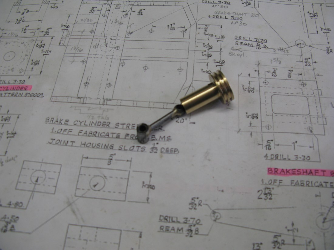
Piston rod and piston

The assembled rod and piston above and its top retaining pin has a potential problem as the pin can float from side to side and thus rub on the cylinder wall. I intend to put a small securing pin either side through the small end pin held in place with loctite. There is no drawing detail of this small end pin.
I will not use cast iron rings on the piston and will simply use graphited yarn when assembled, there is no drawing or mention of any metallic rings anyway.
I was puzzling over how the piston would return when steam pressure was released as there is no mention of a return spring on the drawing. Eventually by chance I was looking at a GA drawing of the cross section of the chassis and on there is depicted a return spring on the piston. So problem solved.
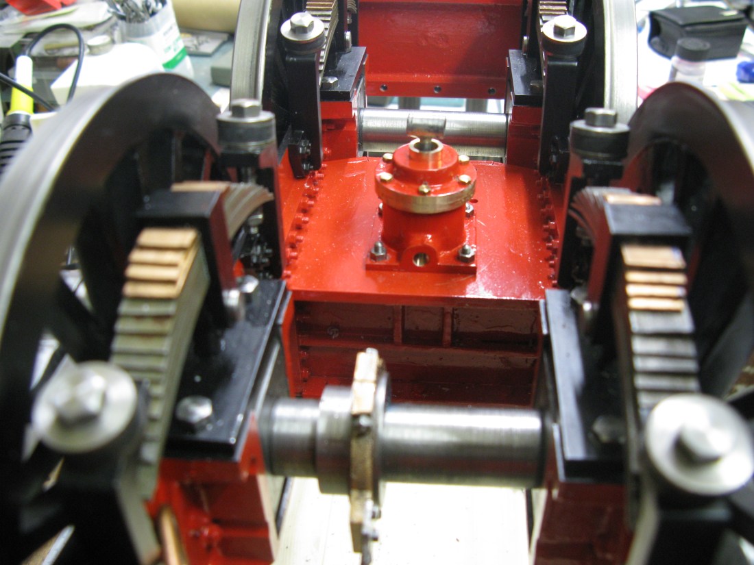
The final assembly of the piston, top cap, piston rod and spring has to be done in order. The spring has to be put on the piston then the top cap over the piston shaft then the connecting rod has to be put in place and finally the small end pin slid into place. This whole lot can then be put on/in the cylinder and bolted down.
The brake operating lever is mounted in its own bracket which is a fabricated affair. It is made up of five pieces which have to be silver soldered together. To assist assembly the base has two slots to accomodate the sides in the right position then the front and back pieces can be slid into position and the whole held together with a a temporary rod through the holes in the top and a jewelers clamp at the top ready for silver soldering.
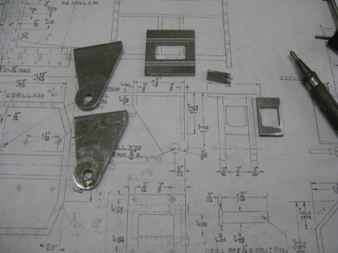
componant parts of the bracket

Silver soldering waiting to be done
All done …. just to be painted.
The brake lever itself is also fabricated from three pieces. The bell crank sides were cut on my little CNC machine. They are held apart by a single bush and to facilitate the silver soldering operation I chose to make the bush with a shoulder onto which the sides could fit. It is unclear from the drawing whether this was intended or not.

Checking all the holes line up before painting the bell crank
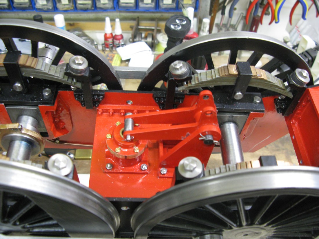
The assembled bell crank brake operating lever
As is often the case when making something to fit, it doesn’t when painted! The bell crank suffered this problem as can be seen by the scraped paintwork. However with much working backwards and forwards and a drop of oil it now rotates freely.
Lots of bits next to make. Links and bars, rods and forks and then of course the brake blocks themselves.
The first bit of the brake assembly is the adjusting link seen above (the bar is upside down at the moment for ease of putting the opin in). It gets a bit more complicated…..
The first brake bar trial fitted, everything the right way up with split pins underneath. Pins not set as it all may have to come adrift again. The brake bar goes inbetween the long links, there is one top and bottom. In fact all the links are double ones. The compensating links eventually connect to the first pair of rods up to the next bar.
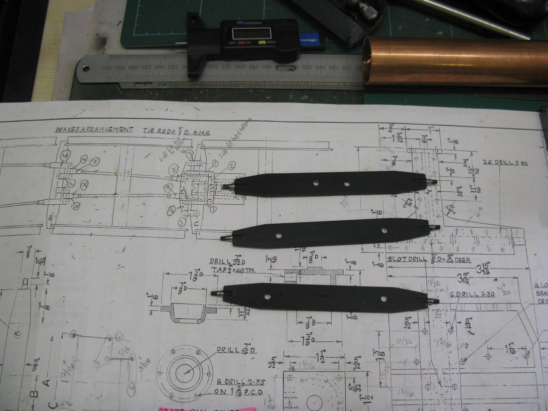
The three brake bars were made by taking the 3/32″ thick bar and angling the ends by hand saw and file, then a 5/32″ slot was cut in the ends and the 5/32″ ends silver soldered in place.

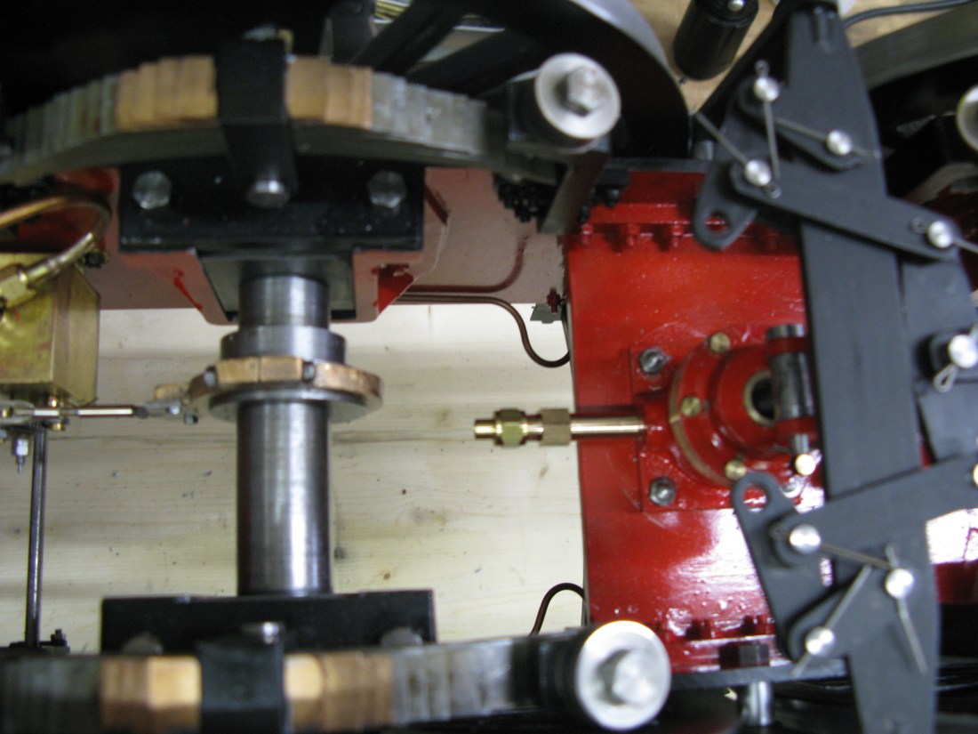
The brake hanger shown here is just to indicate how tight it is for space between the wheels. The brake hanger does not sit as shown but 3/8″ away from the chassis frame and thus brings it out to the centre line of the wheel tread.

Assembled brake hangers showing the spacers to get them to sit on the wheel tread centre line.
Now, the drawing shows a drain plug on the steam entry to the cylinder. It’s simply a block with a cap head screw in it. I could not see it ever being used as it was really inaccessible even with the loco in a steaming bay and the drain would only empty the condensate from the pipe as the piston fits flat to the top of the cylinder anyway so there would be little water in the cylinder. I decided not to fit it. Instead I just put a longer pipe connection in its place.
Steam entry pipe instead of drain plug.
The pipe has to be as it is as there is insufficient room to leave the hex form and turn the unit into the threaded hole.
Moving on to making forks for the rods that connect the brake bars together. A time consuming job. Fortunately I did notice that the was a problem with the drawing as one set of forks was not drawn at all and another set had dimension incorrect as well as the actual as drawn fork not tallying with either the notated dimension or the actual requirement.
To make the forks I first had to mill down some bar stock to get the overall section of 1/4″ x 5/16″. Then the first operation was to saw cut the slot, then drill the hole for the pin and radius the end of the fork and finally in the four jaw chuck turning the end boss and drilling and tapping 5 BA.
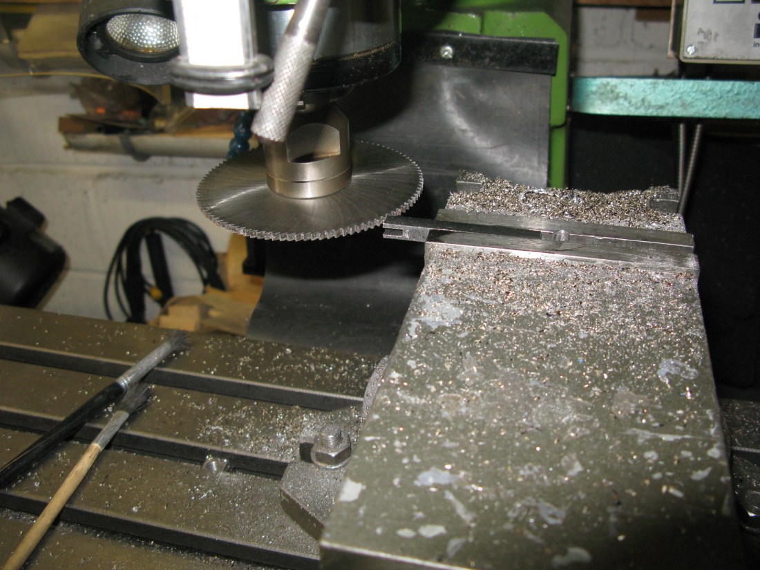
sawing the fork.

Turning the boss end and drilling.

short forks and a long fork waiting to be turned.
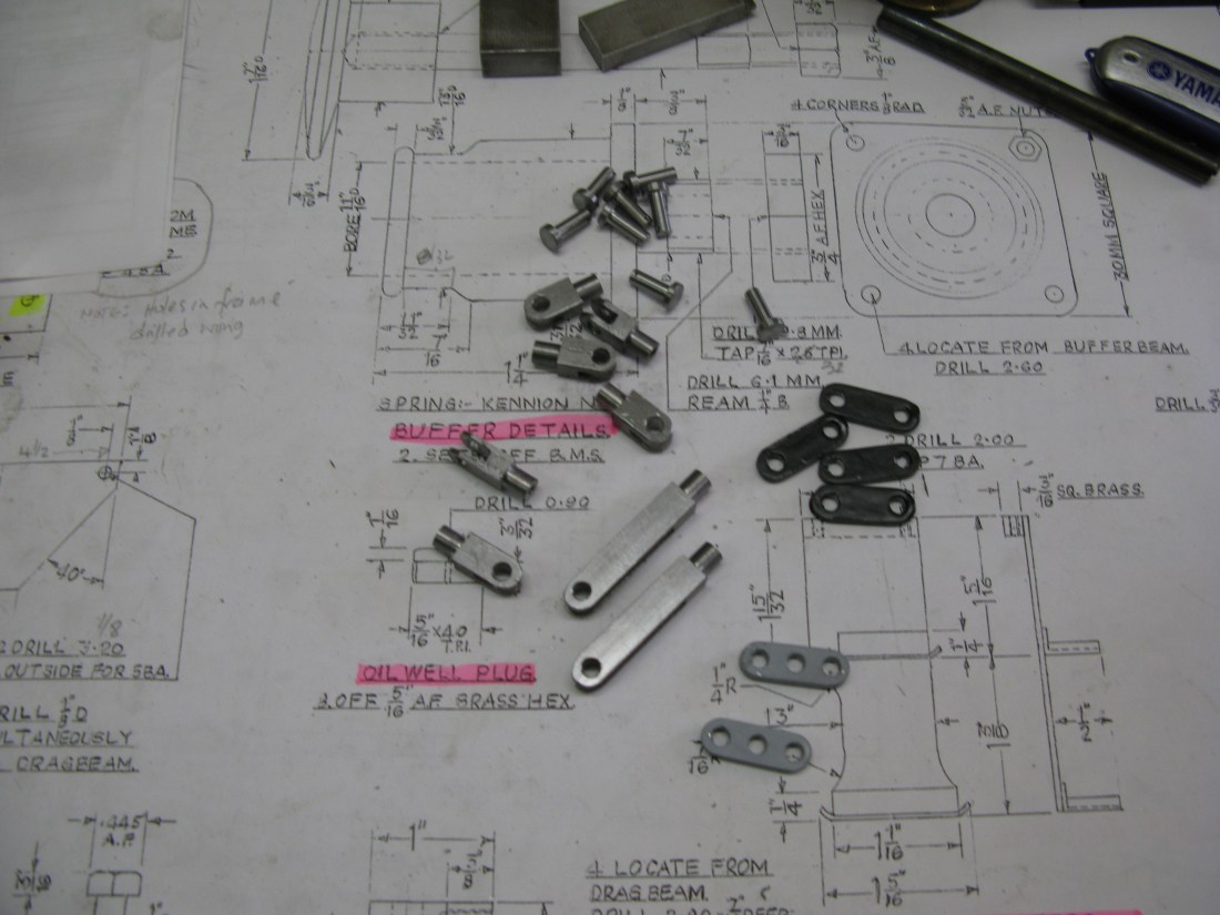
A selection of forks and links and pins
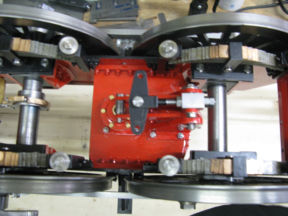
All the brake rods are finished and now fitted.

However the are are no brake shoes yet. The reason being that I am waiting to hear if the casting is still available. The shoes are cast in a ring which makes turning the wheel diameter easy. If it is not available each one will have to be made individually and I will use my little cnc mill to do them. So the slpit pins in the rods have not been clipped off as the rods may well need adjustment when the shoes are fitted.
Well after some weeks I have not heard about the brake shoe casting so I have decided to make them individually.
Each shoe is milled from a piece of 2″ diameter cast iron. They are 5/16″ thick. The hole for the pin is then drilled and finally the 1/8″ slot milled to fit over the operating arm.
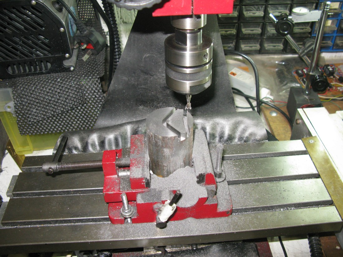
CNC milling a brake shoe
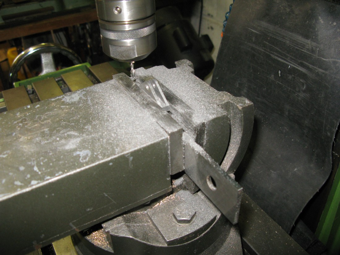
Milling the slot
A fitted shoe
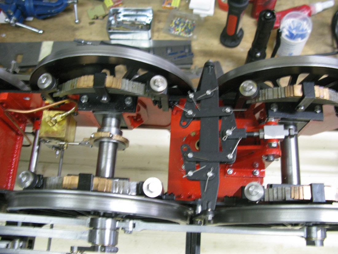
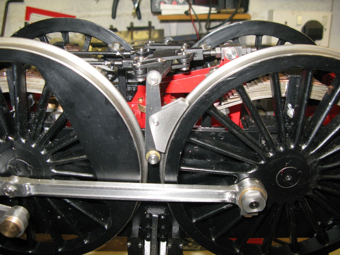
Once all the shoes were done they were painted and fitted and the brake rods adjusted to the required lengths to get the shoe just off the wheel rim.

Thye brake gear is now finished.
