The horn blocks are cast iron castings and they will need machining to fit the slot in the frame and finished to depth and then jig drilled from the frame. The holes are spotted at the rear to give a parallel finish for the fixing washer and nut.
The first machining task is to machine the face that fits into the slot on the frame. My machine set up on the mill was to put a fence in one table slot against which the casting could be clamped and then to use a couple of sheet clamps to take the sideways lateral load. Following a shallow clean up cut of the casting the top was machined down to a depth of 1/8″ leaving the outline ridge of the casting to fit the frame. The casting was then turned over and the back machined down to the specified thickness. The slot for the axlebox was left untouched at this stage as was the length.
To fit the hornblock to the frame it was clamped in position and jig drilled from the frame. The hornblock was then put in a vice on the mill and the holes spotted with an end mill to give a flat face for the washer and nut. Four of the holes are very near the inner edge of the casting and the end mill for spotting the holes will take a semi moon cut out of the side.
The horn block is finally trial bolted to the frame with 5BA C/S set screws, washer and nut.
With all the horn blocks fitted the frames are clamped together back to back. Using the drilled holes 4BA and 2BA screws and nuts can be used to clamp the frames securely once in line.
Using an angle plate on the mill table the frames can be secured upright against the angle plate making sure the angle plate is also parallel on the table. Further clamping arrangements are needed either side of the angle plate to prevent the overhang of the frames from vibrating.
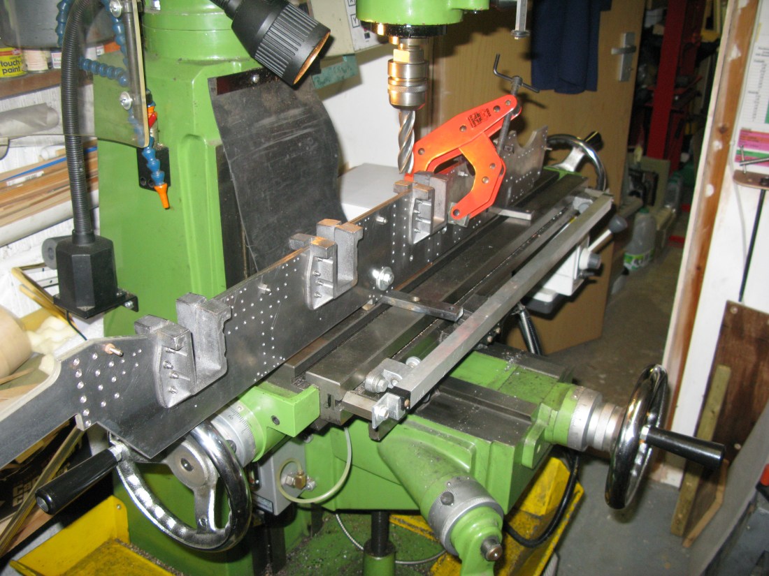
The packing under the frame is to clear the handles. The bolt between the front two horn blocks is attached to another angle plate.
With this set up the horn block pair nearest the large angle plate has the top milled down level with the frame. Once done the whole set up is moved along to do the next pair and again for the last pair.
The next task was to mill the horn blocks for the axle boxes. This entails an accurate measurement of the dimensions from the front of the frame and between hornblocks.
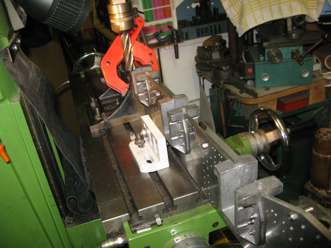
The frames were set up as before but this time a stop was set against the front of the frame and at right angles to them. This set the datum from which the first pair could be milled to size and depth. This can be seen in the photo.

The table is traversed by the required amount to start cutting the front edge of the horn block. In my case a 3/4″ long series mill was used for rigidity. Shallow cuts of 10 thou were taken to the finishing cut but not to full depth as I did not want to cut on the side and bottom of the cutter at the same time. Once the side had been machined the bottom was cut to depth just up to the rear edge to be machined next. The rear edge was then machined in the same manner to give an 1 1/4″ wide hornblock.

Having done the first pair the frames had to be moved along so the second pair were clamped against the angle plate. This time the datum was taken from the slot machined in the first pair. Likewise the last pair were machined having again moved the frames along with the datum being taken from the second pair.
With all maching complete the frames can be seperated.
I mentioned earlier that the frames could not be bent until the horn blocks were machined, well now they are machined the rear set in the frames can be done. The set is inward to give a 5/16″ offset.
The first bend is the worst to do. It is only 1/4″ away from the centre line of the holes that the rear outer frame bolts too and of course the bend will occur at the weakest point which happens to be the hole centre line, unless of course you have access to an industrial machine bender that can clamp over the holes very firmly. Not a facility I have. I have a small plate bender that fits in the vice but the overhang of the frame is too long for the bender clamp mechanism to fit over the holes as the workshop wall is in the way, so the bend was put in with the rear of the frame clamped down but as expected the bend took in the holes as well. As the bend is shallow the bending of the holes is not severe and the rear outside frame will still bolt to it satifactorily. The next bend is 3.265″ away from the first and it must be at right angles to the frame top/bottom. This will give a distance between the bends of 3 1/4″ as drawn. To make this bend I used a vice mounted bender of traditional design i.e. a blade forcing the work into a V slot. The bender (available as a proprietary item) is magnetically held in place in the vice jaws. My 4″ vice exerted sufficeint pressure to make the bend satifactorily.
Check the alignment of the offset by placing the frame over the drawing as well as measuring the offset to be 5/16″.
Having done the first one I tried the vice mounted bender for doing the first bend and found it did the job without affecting the holes. Result!
The rear outer frames can be bent now and I used the vice bender to do the bend near the fixing holes having found out it would do the job OK. However the next bend is too far in and the clearance in the vice insufficient. Fortunately I have a 12t garage press and by using the V portion of the vice bender and a 1/4″ round rod placed on top of the frame the press made the bend OK. Why use the round rod? well the pointy bit of the vice bender is quite wide so box bends can be done and this made for a very unstable part as the press has a lot of free movement on the moving part. The round rod was set up against a scrap piece of sheet steel clamped to the frame to locate the rod on the cenre line of the bend. The press then bought down onto the rod. This worked very well. The bends are such as to give a gap of 1 3/8″ between the outer frame and main frame.
The outer frames are bolted to the main frame with 2 BA set screws. When bolted together the back of the outer frame and main frame should end up level as shown by a square against the frames. My outer frames turned out to be 1/16″ too long. Not sure why this occured as the measurements are to drawing. After pondering a bit I decided to elongate the outer frame fixing holes by 1/16″ with a slot drill which brought them into line.
Interestingly the fixing bolt for the rear frame is a drawn item but is drawn as a 3BA bolt yet the holes are dimensioned for 2 BA.
Cartazzie horns
The final pair of horns are for the Cartazzie axle boxes on the trailing frame. The Cartazzie arrangement is an ingenious way of doing away with a bogie at the rear. The axle boxes slide in the horns which are angled forward which allows the axle to effectively pivot as one side goes foward and the other side goes towards the rear. The axle is centralised by axle spring pressure on angled plates on top of the axle box that slope toward the frames thus the more axle ‘pivots’ the more pressure is applied from the spring on one side to return the axle to a centre postion.
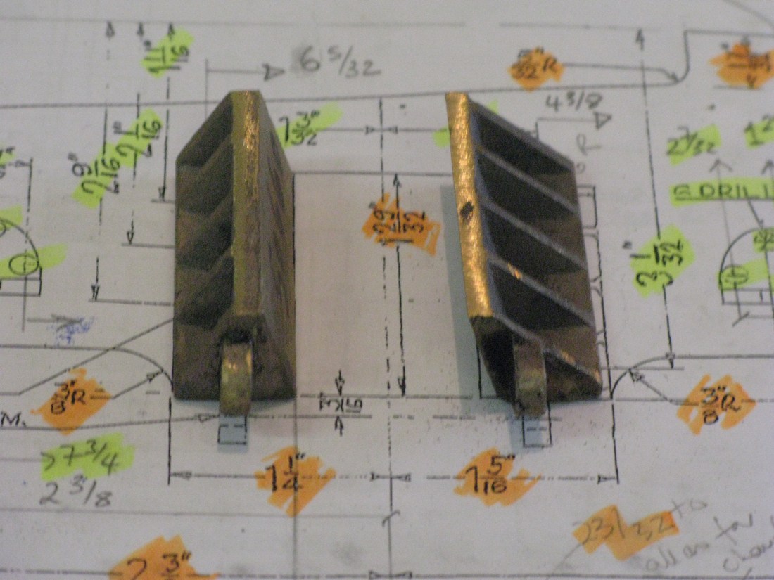
The horns are gun metal castings and have the angles roughly cast. The finished angle for the horn is 17 degrees. The horns come as a stick of two one stick for the front horn and one stick for the rear horn. These are just sawn in two to get the matching pairs.
Because of the angular nature of the horns thay are problematic to hold for any hand or machining work although the rear horn can be clmaped in a vice (with jaw protectors) for some work.
Each horn has a pip at the end which is for the axle box retaining rod.
The method adopted for machining took a bit of head scratching to work out what to do and when and also what to use as a reference. In the end I decided on what at first sight is a suprising reference namely the hole in the pip for the axle box retaining rod. The reason for this was it is dimensioned as being 3/16″ away from the frame and thus gave a reference to machine the face that abuts the frame. So the centre of the hole was marked out and centre punched, the pip cleaned up with a file and the horn casting clamped in the machine vice between its two ends which have just enough material to give a secure clamping surface. As the pip is at right angles to the frame it was a relatively easy matter to set the horn in the vice with the pip on the top of the jaw vice which then set the face to be machined in the vertical plane. Using a long series end mill the face was cleaned up so that it finished 3/16″ from the centre line of the hole in the pip. This was done for all four horns.

The angled face was tackled next. There is no means to clamp the horn at 17 degrees in the machine vice in such a way as the face can be machined across its full length so I resorted to clamping the horn with jewelers clamps to a piece of flat bar and the flat bar set at 17 degrees in the machine vice. An advantage of this was that the dimensioned height of the horn of 5/8″ could be machined using a bit of trigonometry once the face was cleaned up.
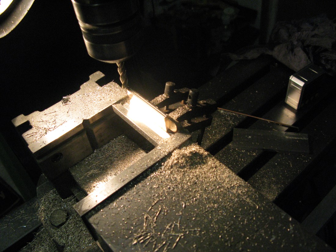
Using a 1/4″ long series end mill the flat bar was first machined across its width in front of the face of the horn block to allow the end mill to reach the full depth of the horn block when machining the face. This took a few shallow cuts as an end mill is not designed to plunge. Once this was done the face could be machined to clean it up. There was no specific dimension to achieve here as the face would be set in its correct position on the frame by positioning of the fixing holes. Having cleaned the face the cutter was raised to 0.654″ and the top of the casting cleaned up to form the right angled edge that is to sit 5/8″ above the frame.
The matching horn had to have the flat bar angle reversed as the jewelers clamps got in the way otherwise, but with that done the matching horns were also machined.
Pairing up the horns following maching showed the angles were almost correct so a little hand filing was employed to take off the small amount on one horn to get its face matching perfectly with its mate. ( makes me doubt the accuracy of the digital angle measuring device).
To fit the horns the trailing frame was taken off the main frame for ease of drilling the horns having clamped each in turn to the frame. Here came a problem as I could not get the horns to align with the frame holes and clear the webs sufficiently for the fixings. I could at best manage three to fit but not the fourth, so I resorted to fitting the three and drilling from the horn through to the frame for the fourth (the top hole) which left an elongated hole in the frame which would have to be “repaired” with the tried and trusted metal repair epoxy. I did check the frame drawing and the holes were in the right place and it appears the casting web for the top hole is misplaced.
The fixings for the horns were 4 BA HH headed screws with the head turned down to resemble a rivet head and with nuts on the inside of the frame.
The first horn to be fitted was the rear one as it could be lined up with the frame edge. Once fitted in place the frame edge was filed flush to match the angle of the horn. The front horn was then fitted using a piece of 1 1/4″ flat bar to give a parallel gap between the horns and the frame edge filed flush and then backed off on the rear to give a parallel edge to the front face of the horn.

The gap between the horns is supposed to be 1 1/4″ but as the axle box will be made to fit the horn any slight deviation will be taken up with machining of the axle box.
