There are two eccentrics to machine, one for the inside valve motion and one for the oil pump. The inside motion eccentric mounts on the left hand side of the crank shaft and the oil pump eccentric mounts on the axle of the middle driving wheels.
The inside motion eccentric is a cast iron casting but the oil pump is machined from bright mild steel.
I made the inside motion eccentric and its strap first.
The eccentric casting was first measured to determin the centre of the shaft and the centre of the throw to ensure enough material surrounded them to machine off. As it turned out it was a bit tight on the overall diameter. The centres were centre popped.
The first machining stage was to use a four jaw chuck to turn the boss which was the centre of the crank axle. The work was centred in the chuck using a point wiggler against the centre pop. The boss was turned to size and width and then drilled and finally bored to fit the crank axle.
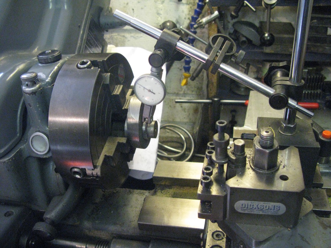
The work was then turned around in the four jaw chuck and now I had lost the centre pop for the eccentric centre as a) I had turned it off and b) it was on the other side anyway even if I had’nt turned it off. In order to get the offset for the throw I employed a DTI on the cross slide and a dummy pin in the axle bore against which the DTI could rest. By finding the high spot by turning the chuck so the dummy pin was nearest to me and zeroing the DTI and then moving the work 180 degrees to find the low spot with the DTI on zero the movement of the cross slide gave twice the offset. This took a little bit of fiddling to adjust the chuck and then doing the measurement time and again to get it just right. Once done the outside diameter was turned down and to get a clean face it had to be slightly undersize but it still left sufficient wall depth for the strap to fit into. Using a parting tool the slot for the strap was turned and then the whole faced off to the required width.
That completed the eccentric except for the method of fixing it to the shaft. The drawing shows a simple allen screw through the boss onto the crank axle which seeded to me to potentially be a problem should it allow the eccentric to move. A dimple on the shaft would secure it better but a better solution was to put in a key. At this point I was undecided.
A further difficulty was where the eccentric centre should fit on the shaft in relation to the crank pin as the drawing gave no information at all. Looking at Walshearts gear it seemed that it should be 90 degrees after the crank pin when in forward motion. However other references indicated that whilst it is about 90 degree the actual position is dependent upon the line between the bottom pin of the expansion link and the centre of the crank axle and the eccentric centre has to lie on a line at right angles to this line which could make a degree or so away from the 90 degrees. More checks are needed as there is no drawing where this line can be established. So the eccentric fixing is in abeyance.
With the eccentric put to one side I decided to make its strap. It is a gun metal casting and using a three jaw chuck with the jaws inside the casting one face was turned flat. The strap was turned around on the chuck and the other face turned flat and to width so it just slid into the eccentric slot. With the strap off the lathe a centre line was scribed where it was to be cut in two.
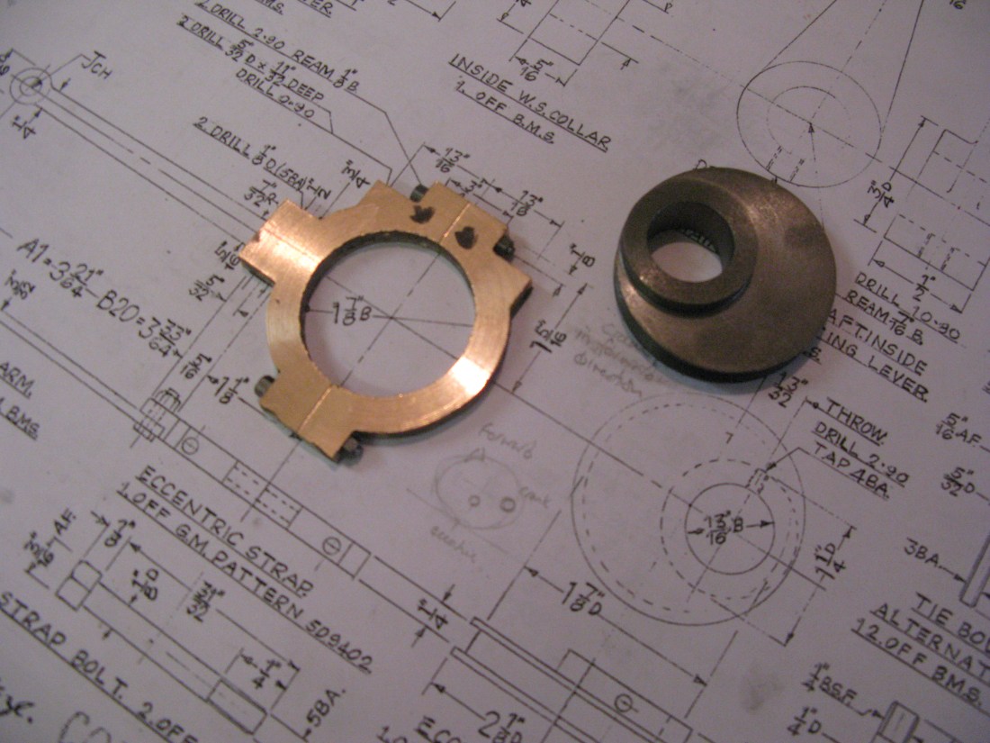
The finished eccentric cam and the part machined strap
The next task was to drill for the two clamp bolts and this was done in the mill with the strap in the vice set level by reference to the centre line scribed to take advantage of its DRO to get the two 1/8″ holes in the right place.
The eccentric was cut into two with a slitting saw on the mill and two machine bolts turned up from 3/16″ AF hex BMS with a 5 BA thread. These fitted into the strap to hold the two halves together.
The strap had another centre line scribed at right angles to the split and using these lines as reference the strap was centred in the four jaw chuck to turn the bore to match the eccentric cam.
Back to the mill to drill the two oil well holes 5/32″ for the well and 1/16″ to feed the strap. This leaves the remaining machining to do which is to make the recessed flat for the strap arm to bolt to.
I had another browse of the drawings and found the general arrangement and longitudinal section of the boiler had the centre cylinder motion work drawn but not dimensioned. From this it could be ascertained that the eccentric follows the crank by 96 degrees to an accuracy of the drawn items and my protractor. This has led me to leave any fixings for eccentric until all the motion work is in place and then it can be adjusted by reference to the valve events.
Back to finish the strap and I machined the recess for the strap arm attachment only to find I have done it on the wrong side!. It is not a major problem and just means the eccentric rod will have to have a slight set I suspect to get it to line up with the expansion link. Alternatively the eccentric might be moveable on the crank shaft. I will make the motion work and leave the eccentric rod until last so it can be measured and aligned by whichever method is available to me.
(Much later !) Having made the motion work the eccentric rod was made with a set to align with the pin on the expansion link as the eccentric and strap were up against the web of the crank.
To position the eccentric at the right place relative to the crank I set the assembly up on the mill table in the dividing head. The DTI (set at centre height) was used to establish the top dead centre of the big end and the angular measurement noted on the scale.

With the angle noted, 96 degrees was added and the crank turned in the forward motion and the eccentric turned to a position where it too was at top dead centre.

The top dead centre line can be seen marked on the ecentric
The two grub screws holding the eccentric were then tightened followed by the eccenric boss and axle being drilled to take a silver steel pin loctited in position.
Pump eccentric
The pump eccentric is made from BMS bar and turned down in the four jaw chuck and its slot machined and then offset in the chuck using the same technique descibed earlier. The boss is then turned drilled and bored to fit the axle. The eccentric is clamped to the axle by a grub screw in the boss But I am leaving that for the time being until I know exactly where the pumps is going to fit on the frame so the eccentric arm can be aligned with the pump ratchet mechanism.
The strap is a gun metal casting and after cleaning up the flash it was faced in the four jaw chuck. The centre bore was too small to be able to use the chuck jaws inside to face the other side so the strap was clamped on the mill table and half of it milled down to 3/16″ (to fit the eccentric slot) and then the clamps moved to machine the other half.

The pump eccentric and strap
The strap had its two fixing holes drilled for 7BA clearance and it was then cut in two on its centre line. The two fixing bolts were then machined and the two halves bolted together and centred in the four jaw chuck by using pre scribed centre lines on the strap. The bore was then machined to fit the eccentric. Finally the strap arm fixing holes were drilled and tapped for 8 BA and then the recess step for the strap arm machined.
