The commercially built boiler has been made and collected (13th Feb 2018) and the photo below shows it temporarily resting on the frames without any front boiler support so it looks at a peculiar angle.
I will not be doing anything with this for a while, this is just a blog record that it has arrived.

Boiler saddles
The two saddles are castings, the front one sits over a frame stretcher behind the crank axle and the rear one fits over the steam brake bracket under the wider section of the boiler.
The front saddle casting was definitly “wonky” not a parallel face anywhere. Also the drawing instructs the casting to be modified as it is too wide and does not allow room for the weighshaft connecting rod and I think drain cock rods have to pass it also. The modification instructs to machine away the end webs and silver solder in new ones at the correct width, all to be done before maching proper.
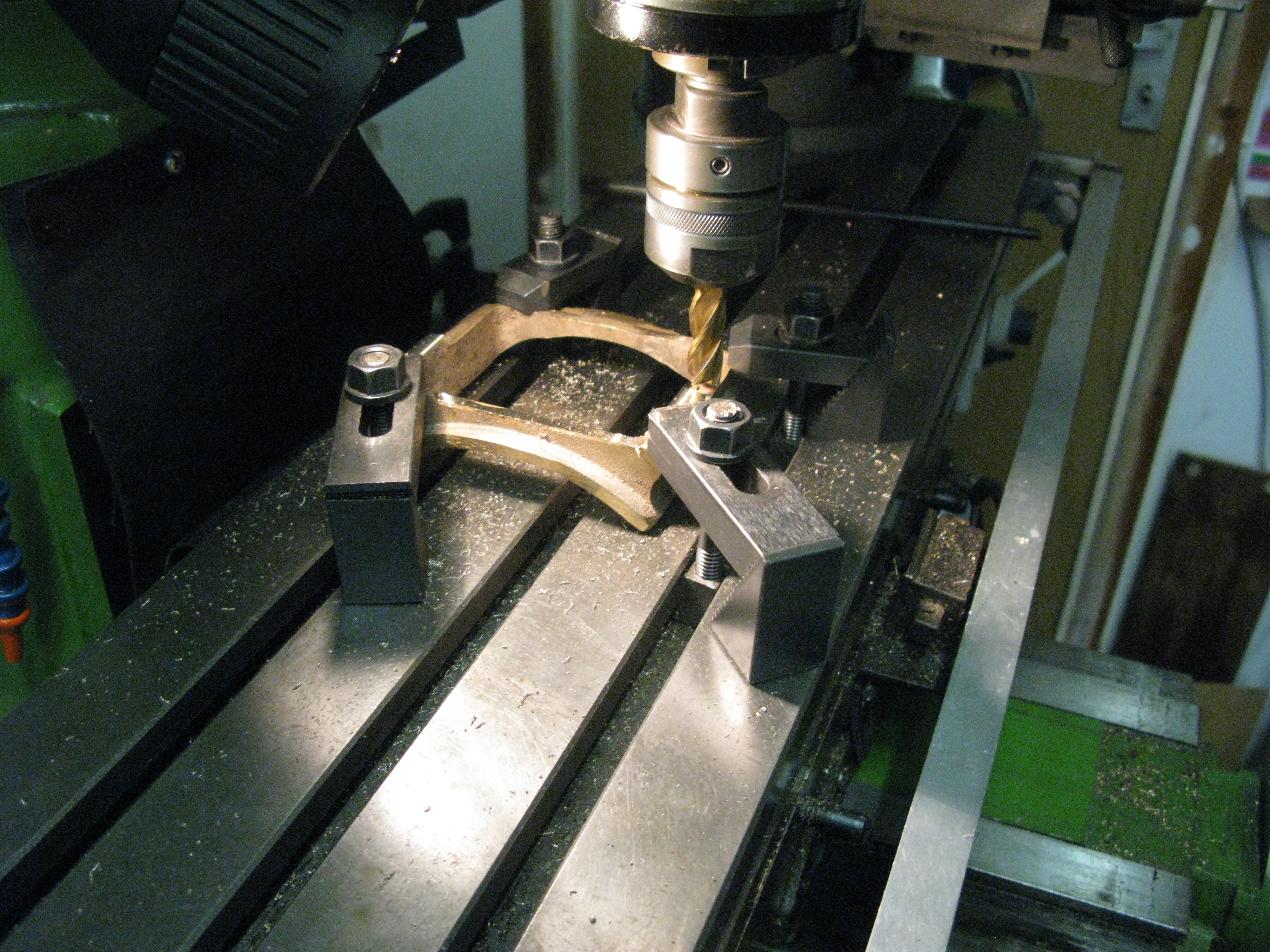
So without any paralle faces to clamp holding the casting was the first problem. In the end I used packing pieces in the machine vice to get a solid grip and aligned the casting as square as possible as I planned to machine the whole base whilst in this set up as trying to reset it up would be nigh impossible, and doing so would give me a square base from which to work and hold the saddle for subsequent operations.
Following the instruction to machine away the side webs I found they did not machine away completely to reach the correct width so I reasoned that I would leave them like that (hardly seen under the boiler anyway) and save myself some work.

Right hand side machined. Left hand side as cast
The base was then machined all round and flat leaving sufficient material above the base to machine the radius for the boiler.
It is worth noting at this point that the saddle radius to be machined is 1/16″ larger than the boiler radius. Looking at the sectioned side view of the Loco there appears to be a 1/16″ packer between the saddle and boiler. This is probably there because the drawing appears to show the boiler with a slight slope towards the smoke box and is not parallel to the frames. No doubt I will discover when I come to fit the boiler.
Anyway back to the saddle. The base has a 1/32″ deep slot that matches the ridge in the stretcher to which it bolts. However the bolt holes are half in the slot and half out, why? no idea. They are 5 BA and could have been moved either way to miss the transition line.
There was little chance of easily drilling the holes once the slot was machined so I drilled and tapped the holes and then machined the slot.

With the base done the saddle could be mounted in the machine vice for the saddle part to be machined 1 1/8″ wide, then changing the clamping arrangement so the saddle radius could be machined. The vice with the saddle clamped in it was first centered in the Y direction and then the X direction was set to zero by a square vertical on the vice base against the base of the saddle. The X direction could then be moved 13/32″ , the dimension of the saddle base to the bottom of the saddle and set to zero again.

The saddle radius is 3 3/16″ and I chose to fly cut it using the boring head. To set the tool to the correct radius I first set the tool agains the vice jaw which is 1 5/8″ off the centre line. The tool could then be measured from this datum to get the 3 3/16″ radius.

My boiler construction is a butt and strap arrangement so I need a slot in the saddle to accomodate the strap.

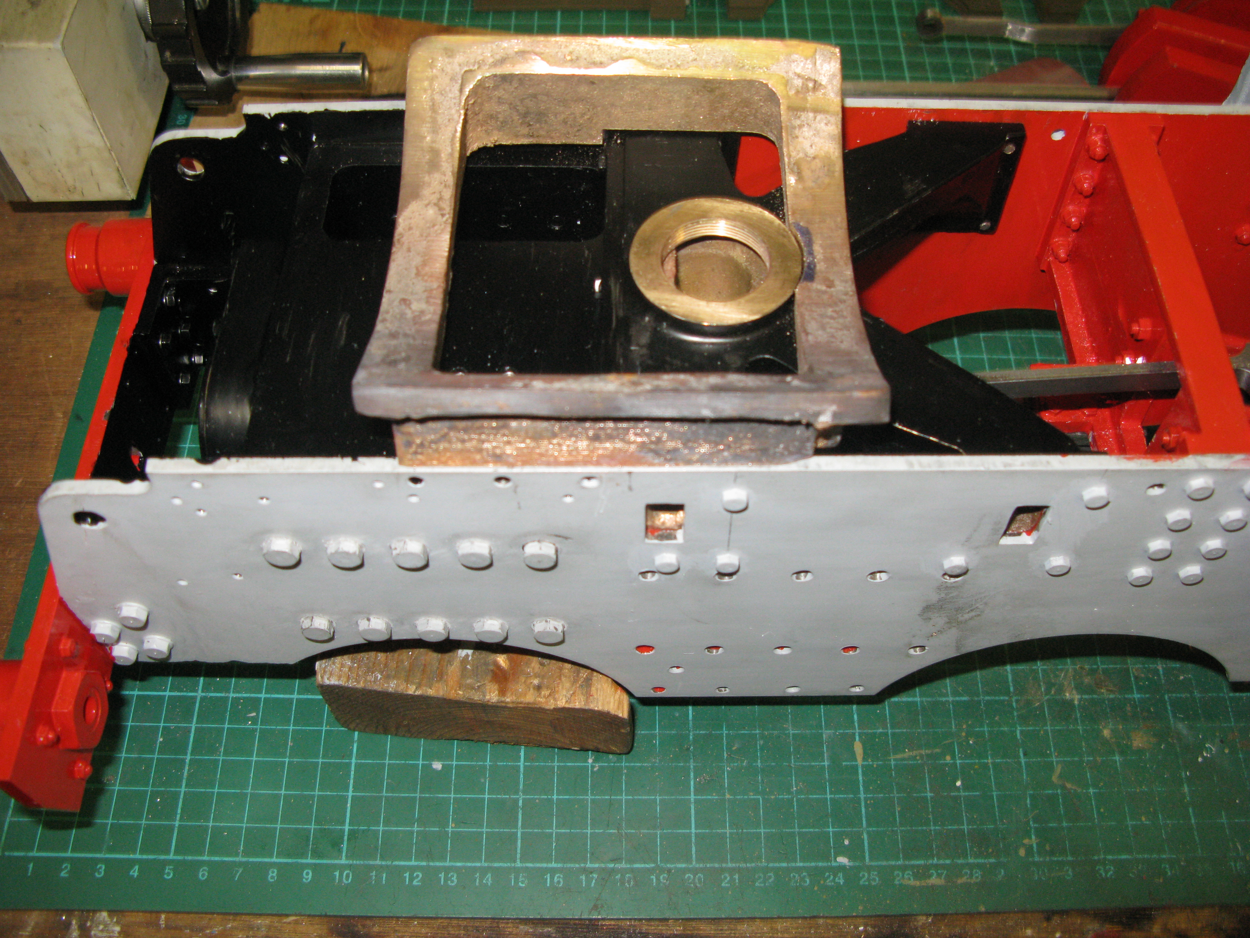
The saddle in position
Fitting the saddle to the stretcher is a bit of a fiddly exercise to get the 5 BA set screws in. It really has to be done from underneath and a slim box spanner will just fit over the outer heads whilst an open ended spaner is a bit more fiddly to use.
The rear saddle casting was only a little better than the front so I followed the same process of machining the base to get a rectangular reference. I cannot say I am impressed with the quality of these two castings. As the casting was clearly very much oversize on it base depth I did mark out the bottom of the boiler radius point on the casting and then the underside of the base at 3/8″ (as dimensioned) from that so I had a line to machine down to. There are quite a few dimensions missing off the drawing but they can either be inferred from the steam brake bracket or scaled from the drawing. Whatever way I was going to machine it I was going to end up with thick and thin areas. It was never going to end up fully symetrical.
This saddle does not have the slot running through the base so drilling the fixing holes was not going to be a problem.
When fly cutting the 3 7/16″ radius it became more obvious that I was going to end up with thick side and an opposite thin side. Had I tried to centre up this radius to obviate the mismatch I would have ended up with very little end web on the base on one side and probably still have a thick and thin webs as the photo’s below show. Just as well it will not be too noticeable under the boiler.

The finished rear saddle …note the web thickness are all quite even

Now look from the other side to see the difference!
It’s worth noting at this point that either side of the saddle are oil wells that provide oil to the rear axleboxes and they bolt to the frame and one of those bolts has its nut sitting between the frame and the saddle in the 1/16″ gap ! I have not found a drawing for these oil wells but they are shown on the general arrangement. They will certainly have to be fitted whilst the frame is accessible.
Update on the oil wells. I found the drawing for these items…. next to the coupling rods! Just a single elevation view but it shows the well with the fixing holes tapped so the fixings have to go from the inside of the frame which means before the saddle is fitted as one fixing hole is covered by the saddle. I could take the saddle off but have decided to fix with through holes in the oil well and nuts inside the frame.
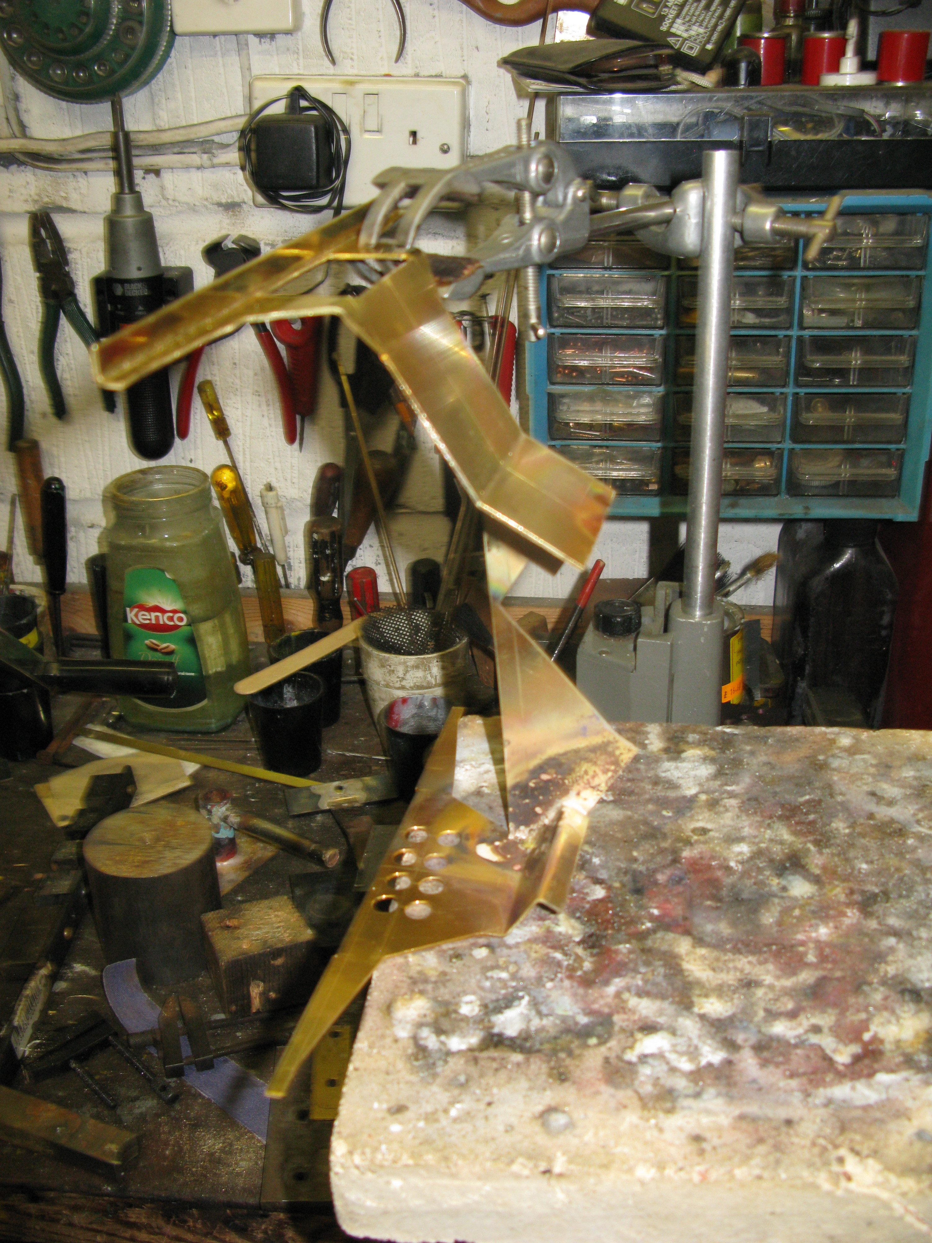
Smoke box saddle
The smoke box saddle is a gun metal casting. The drawing gives alternate dimensions without identifying which loco the alternates are for. I measured my boiler and established that the boiler diameter was 6 5/16″ and the alternate wall thickness for the smoke box was either 10g or 13g. Well, 13g is 3/32″ so 6 5/16″ plus 3/16″ is 6 1/2″ which is one of the alternate measurements for the smoke box OD and thus the curvature of the saddle.
The saddle is stepped so it can fit over the K exhaust, the front step being used to fix the saddle to the frames by 3 bolts each side. The drawing alternate dimension for the 6 1/2″ smoke box shows 5/16″ between the smoke box radius and the bottom of the front step.
With all the dimensions extablished the first task was to get a flat surface as a datum from which to work. The obvious choice was the underside and placing the casting on the mill table upside down it appeared that it was nearly level so I chose to clamp the casting downs and machine the base to get a flat surface all round. The dimensions for the step from front or back of the saddle are not drawn so they were scaled from the drawing. There was only the slightest of cuts to get the step in the right place. The full depth of the step (5/16″) was not machined at this stage.
The next task was to establish a line on the casting where it would fit to the top of the frames . The web of the smokebox saddle is drawn at about 1/8″ thick so I mounted the casting on the mill table clamped so it was firm on the flat face just milled and scribed a line 1/8″ above the underside of the saddle web. This was the datum to which the saddle radius would eventually be machined. From this line I could measure and scribe a line along the side of the saddle where the top of the frame was going to fit and thus set the whole saddle to the correct height.

Having got the machining line for the frame top the saddle was firmly bolted to the mill table with a sacrificial base so the step could be machined. This was done using the set up shown in the photo.

The first cut was done on both sides to get a parallel edge so the overall width could be measured. This done the amount to be taken off both sides could be established. At this point the mind went into stupid mode and I totally miscalculated the depth of cut on the first side and took too much material off. Having returned to sanity mode the other side was cut to the required depth. To rectify the error I silver soldered a strip of brass along the step which brought the overall width to 5 thou below 4 1/8″ being the required width to fit between the frames.
A trial fit showed that there were three problems. The first was the step to clear the K exhaust. It fouled the front lip of the cylinder block so the step as drawn was in the wrong place. Secondly the rear fixing hole is right up against the lip of the cylinder block which means the saddle hole is right on the very edge of the casting and time will tell if it can be drilled and tapped OK. The third problem was that the K exhaust outlet boss to the stack fouls the inner edge of the saddle so a small radius will have to be machined in it to clear the boss.
Having rectified the step position and the clearance for the K exhaust boss the saddle was trial fitted.
The three fixing holes have yet to be drilled and tapped.
Progress. I have now drilled the fixing holes and as feared the one on the right up against the step is right on the edge and not enough material to tap the thread. I shall end up with a smaller set screw through the hole with a filed down nut on the other side. The set screw will have to be purpose made so the head size matches the other two.
However before fixing the saddle I have to find a way of machining the curvature for the smoke box. There is no means for clamping in the vertical on an angle bracket mounted on the mill as the whole curvature has to machined in one go. It am considering putting a bar inbetween the sides and using the fixing holes just drilled to fix the bar in place and then the bar can be fixed to the angle bracket.
Before machining the curvature to 3 1/4″ radius to fit a 6 1/2″ smokebox diameter I decided to check the alignment of the smokebox with the boiler bottom to verify the 5/16″ dimension on the drawing for the height of the bottom of the curvature to the base of the saddle.
I mounted the boiler on the frames and the first thing noticed was that the expansion link is proud of the top of the frames when in mid gear by 1/16″. This means the underside of the smoke box must clear this.
This then determined the underside dimension of the smoke box in the saddle and the saddle scribed accordingly . It did not match the as drawn 5/16″ dimension. There was very little to be machined off the front of the saddle and none off the rear to achieve a level saddle. The next thing noticed was that the boiler front sat too low for it to slide into a 3/32″ walled smoke box and this now explains why the elevation drawing of the loco has packing pieces drawn on the front saddle to raise the boiler front up.
Having now understood the issues of aligning the boiler and smokebox I can turn my attention to maching the smoke box saddle curvature.
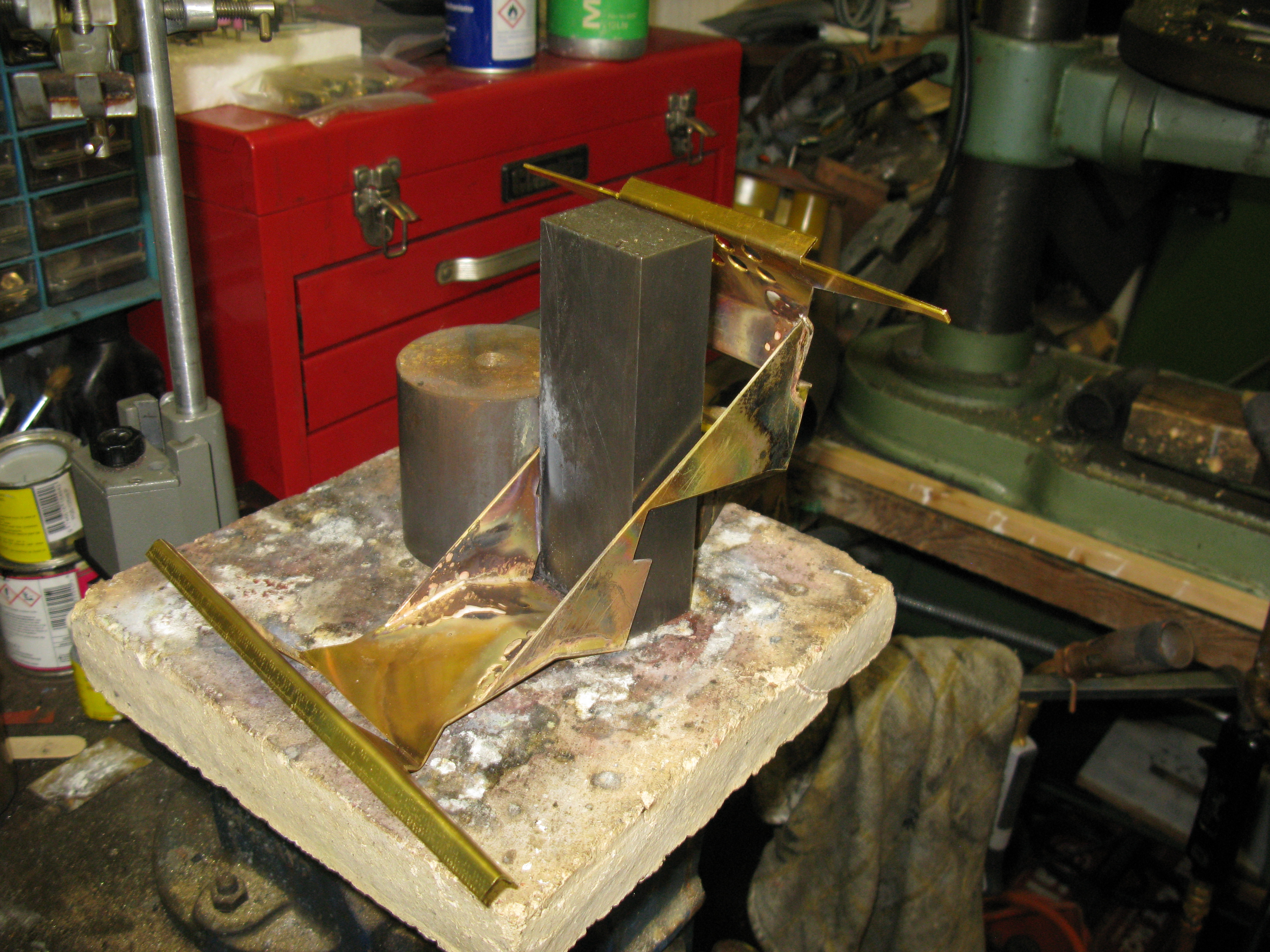
The saddle having a step on its underside was difficult to clamp securely to the angle bracket on the mill bed. To overcome this I fixed a parallel bar to each side with the top of the bar firmly aginst the top of the rebate that the saddle uses for mounting in the frame and held them there with 4 BA set screws using two of the holes that are used for fixing the saddle to the frame. The third hole could not be used as it’s blind. With the two parallel bars fixed I checked everything was still level, i.e. it did not rock when placed on the mill bed. I then fixed a wide bar inbetween these two parallel bars and fixed it to the parallel bars with 4BA set screws in tapped blind holes in the wide bar ends. Three 5/16″ fixing holes in the wide bar were then drilled on the slot centres of the angle plate. The photo below shows the set up. The middle fixing hole was not needed, it was firm enough with just two bolts. The spacer below the saddle is just to give clearance to the boring head set up and was removed for cutting.
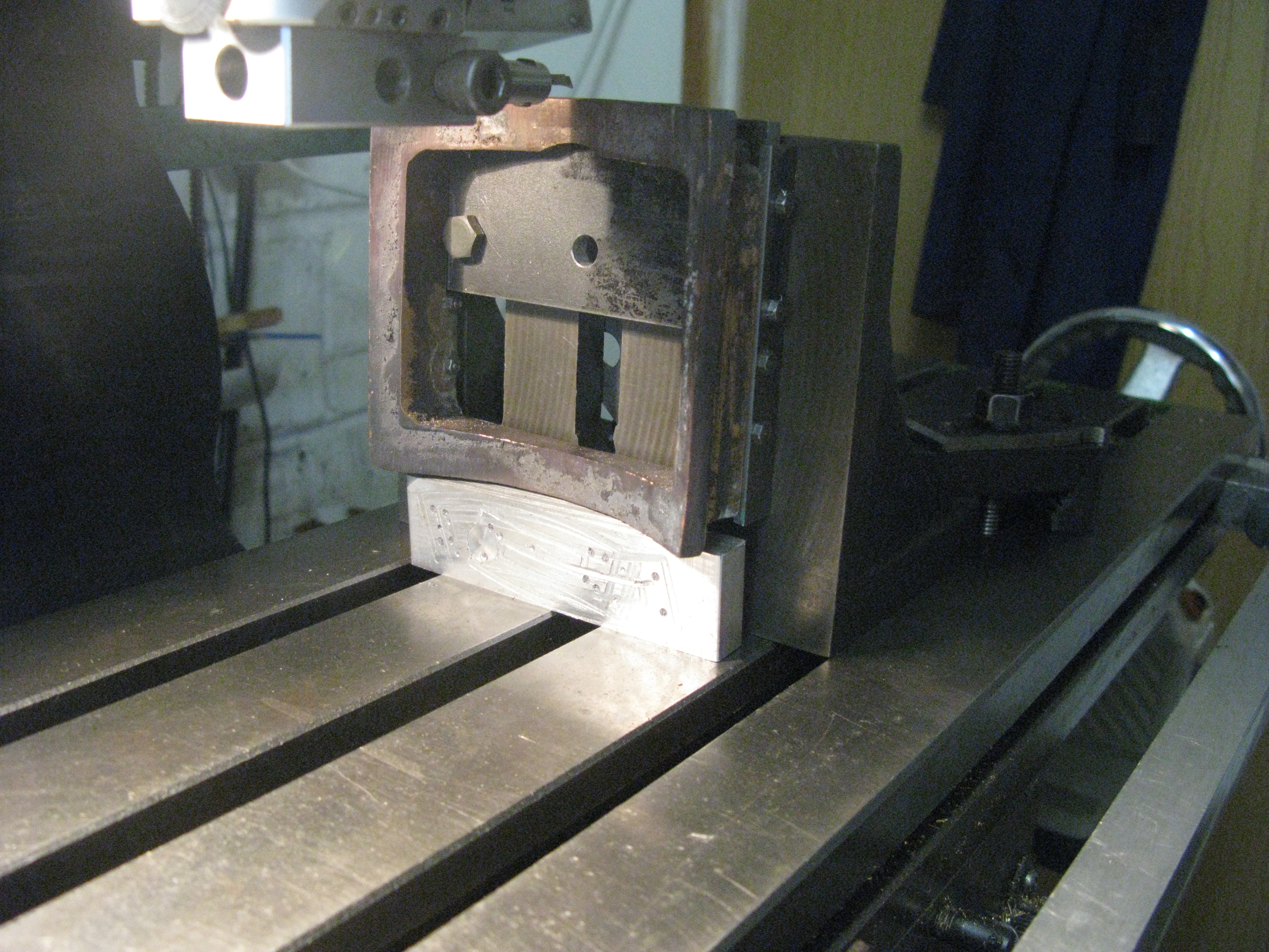
The saddle was checked to be square on the angle plate before finally tightening the fixing bolts.
The set up on the mill was achieved by first setting the face plate surface on the X table on the centre line of the quill and setting the DRO to zero. Next the Y table was centered around the saddle by a centre finder on each edge of the two parallel bars and dividing the measurement by two to give the Y centre line of the quill and the DRO set to zero.
The boring hear arm was set to 3 1/4″ by moving the angle plate surface back in the X direction to 3/14″ from the quill centre line and setting the tool tip aginst the angle plate surface.
Finally before starting any cutting I moved the saddle to the X position so the tool was at the final cut position as scribed on the saddle and hand moved the tool to check the swing and where the edges of the saddle would be cut to see if they were reasonably equal …… they were, so the set up was a success.
The cutting process was taken in 15 thou steps to avoid too much “hammer” on the saddle and with only 3″ of quill movement I machined down to the limit of the final cut and then moved the mill table up and finished up the last 1″ of the saddle machining in steps as before. The final cut did not quite clean up the last 1/2″ of the saddle curvature in the central part of the curve. As its under the smoke box it will not be noticed.
Boiler work
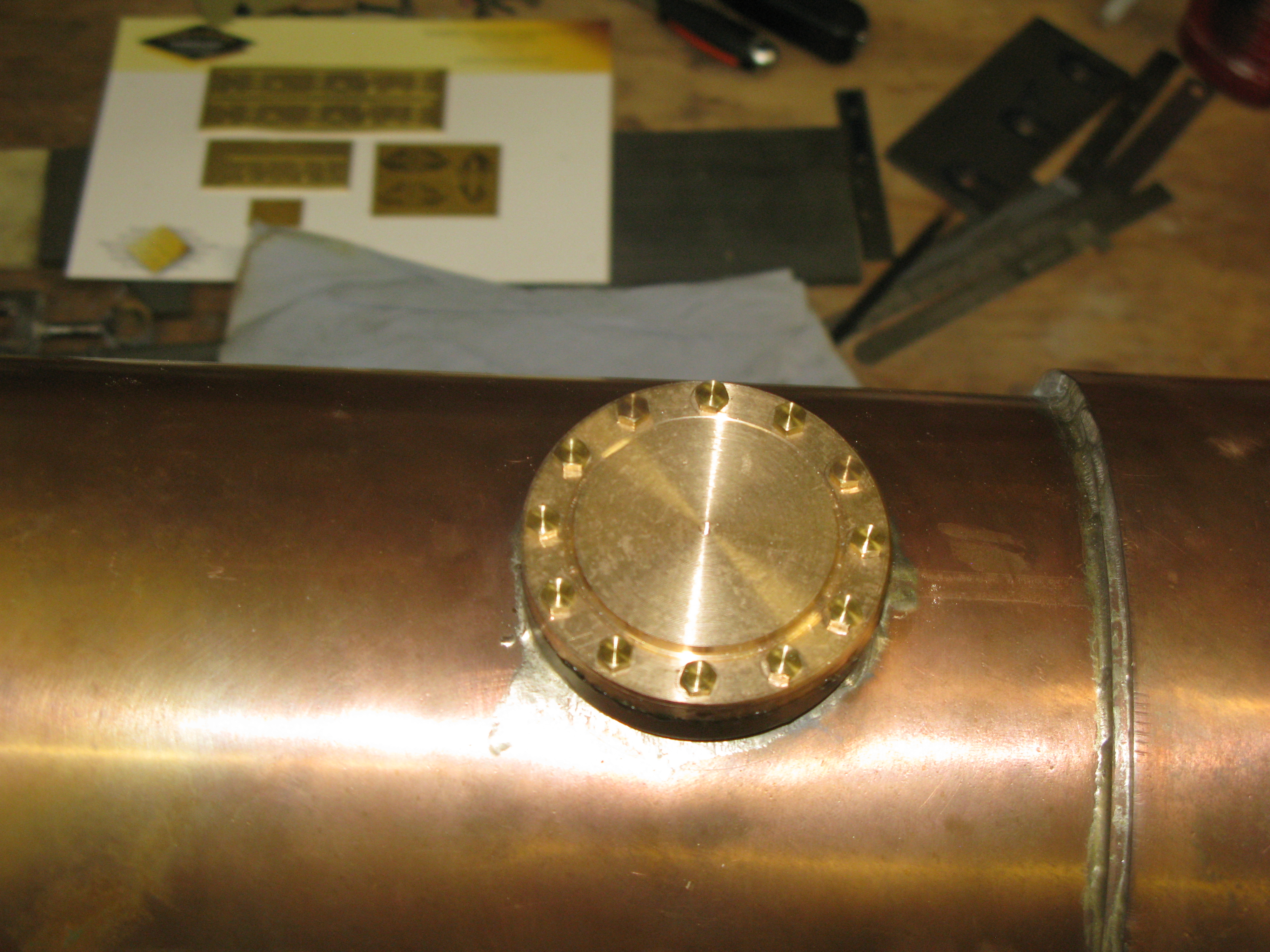
Getting back onto the boiler the regulator dome was the first job. This was turned from a casting and then drilled for the fixing bolts. The drawing specifies 18 fixings but I chose to do 12 purely because 18 looked close together. It might be prototypical, I don’t know, anyway it turned out to have a benificial outcome.
Looking forward I browsed the regulator valve that has to go through the dome to be fitted and noticed that it is drawn as being screwed to the boiler by two c/s screws. Technically if I drill the boiler shell it would invalidate the pressure test. I was not happy with this. However only having 12 bolts in the dome means there is enough space between two bolts to fit a fixing screw for the regulator valve so I can get the two fixings into the dome bush. As the dome cover bolts on top of these fixings I claim that I am not invalidating the shell test of the boiler. I will have to wait and see if my club boiler inspector agrees.

Drilling the holes for the dome fixing
 The dome cover was used to jig drill the dome bush to ensure all the holes aligned correctly.
The dome cover has to have some further minor work to complete it as the regulator valve spring has to be fitted to the under side which is screwed to the cover. Also there is an adjusting screw to be fitted in the dome centrally to adjust the pressure of the spring.
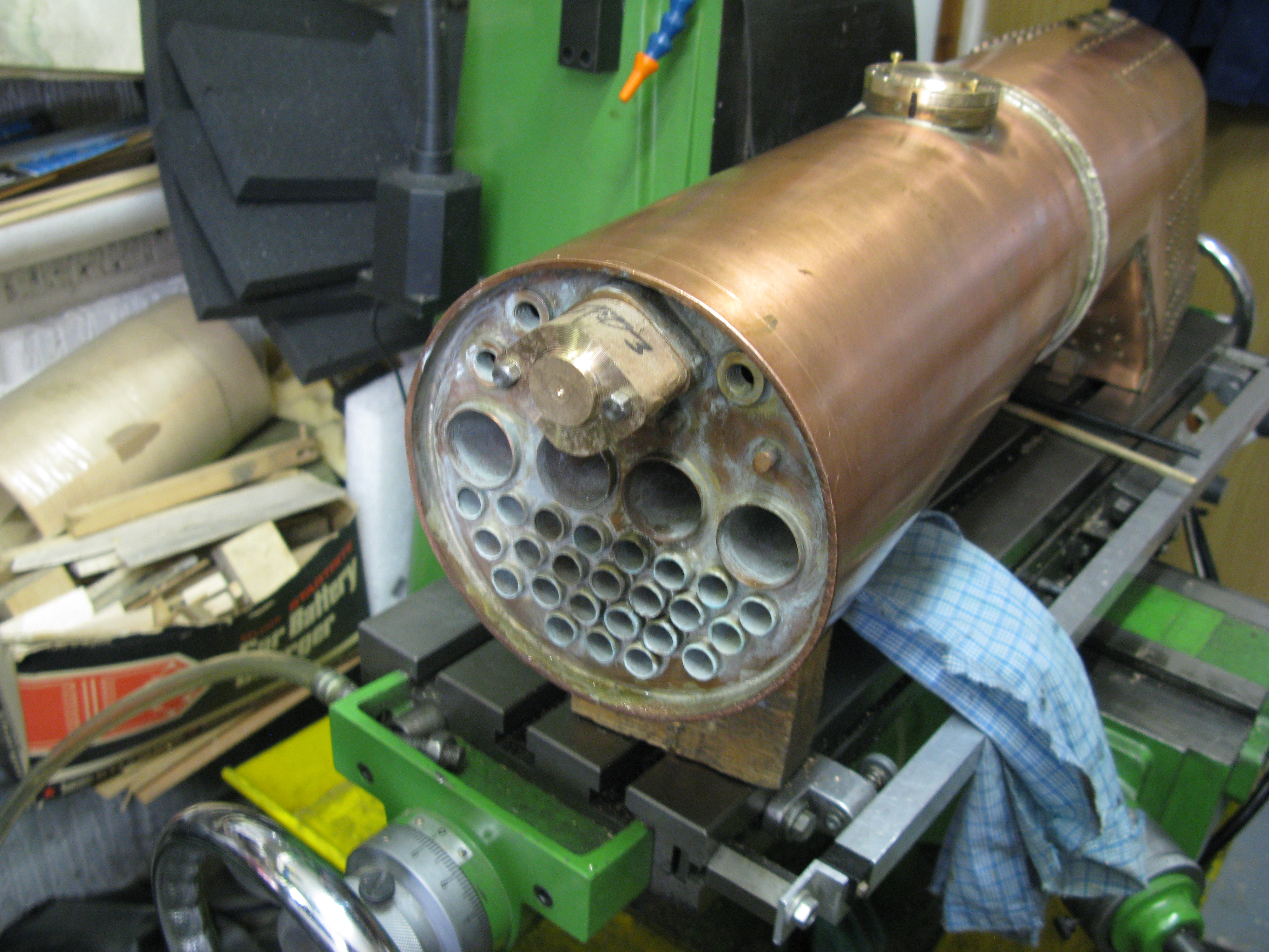
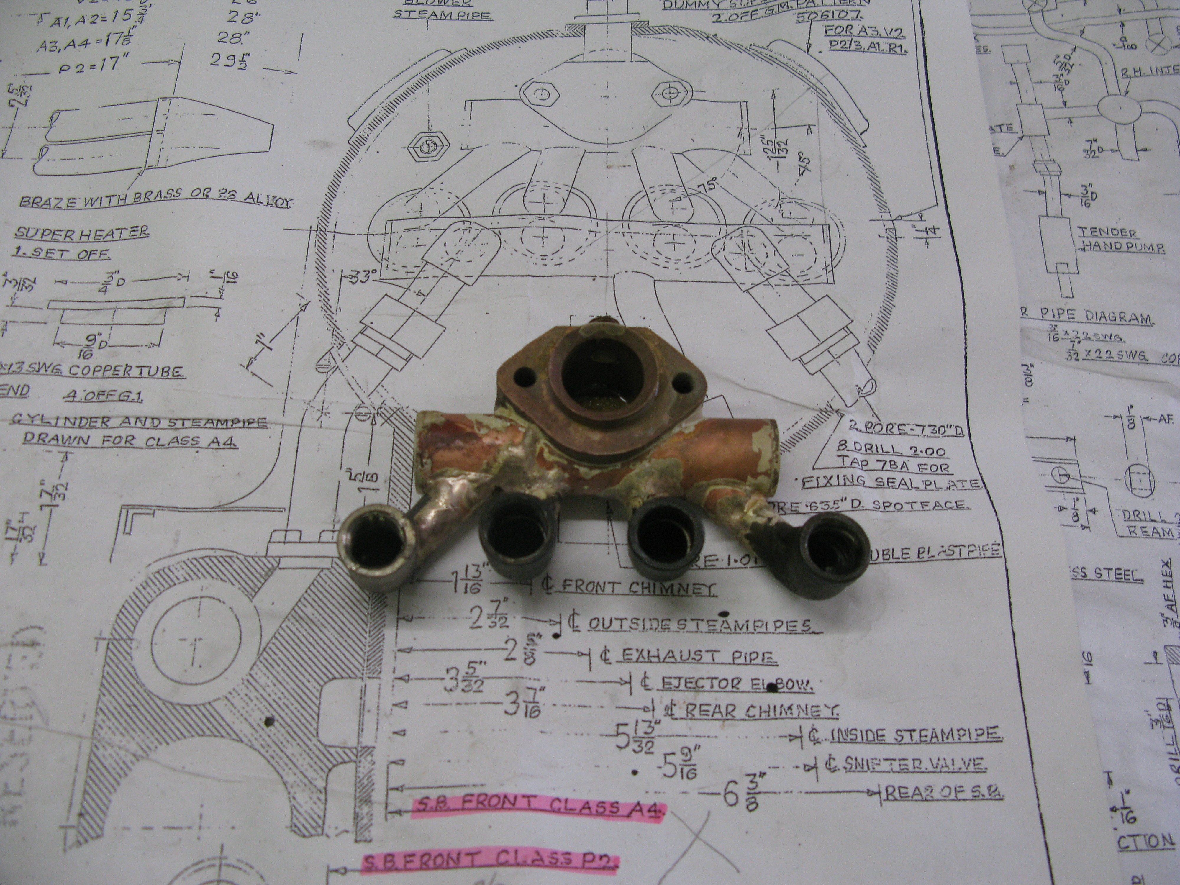
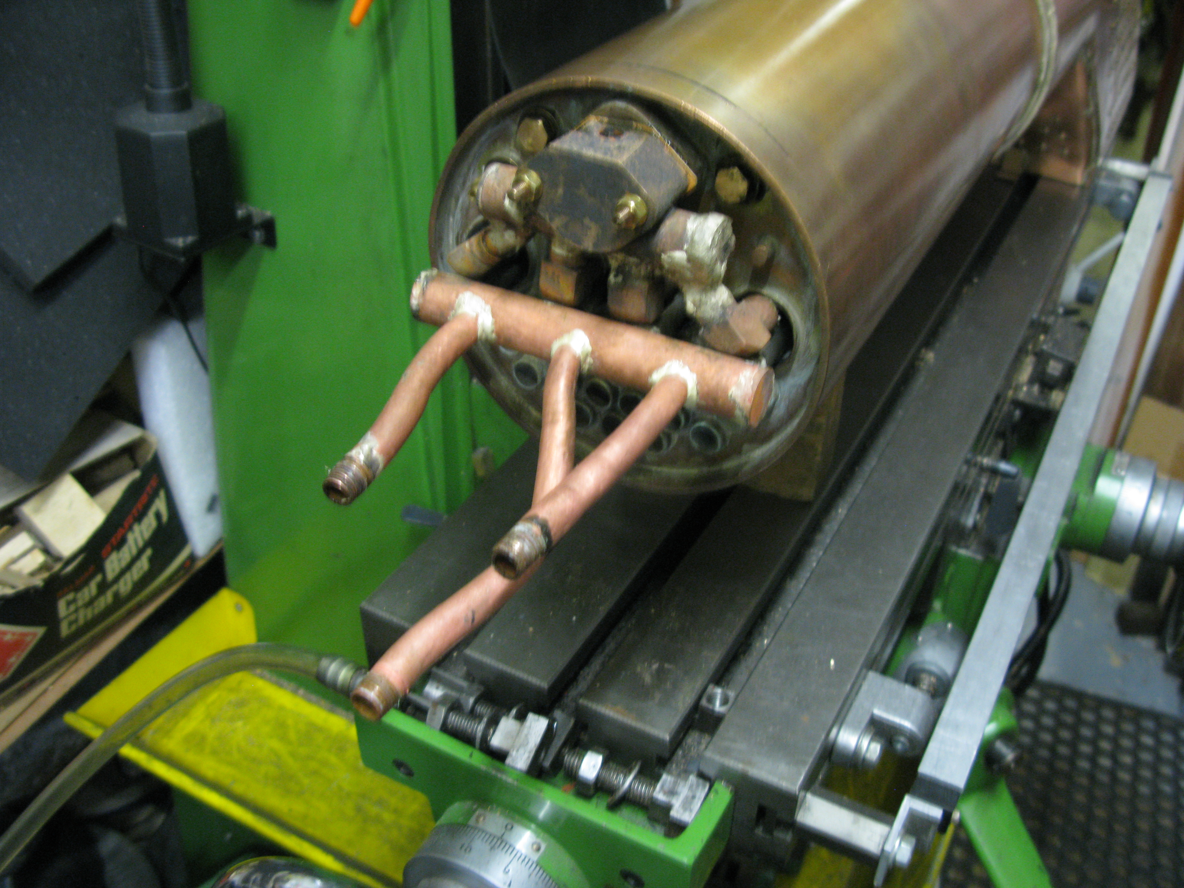
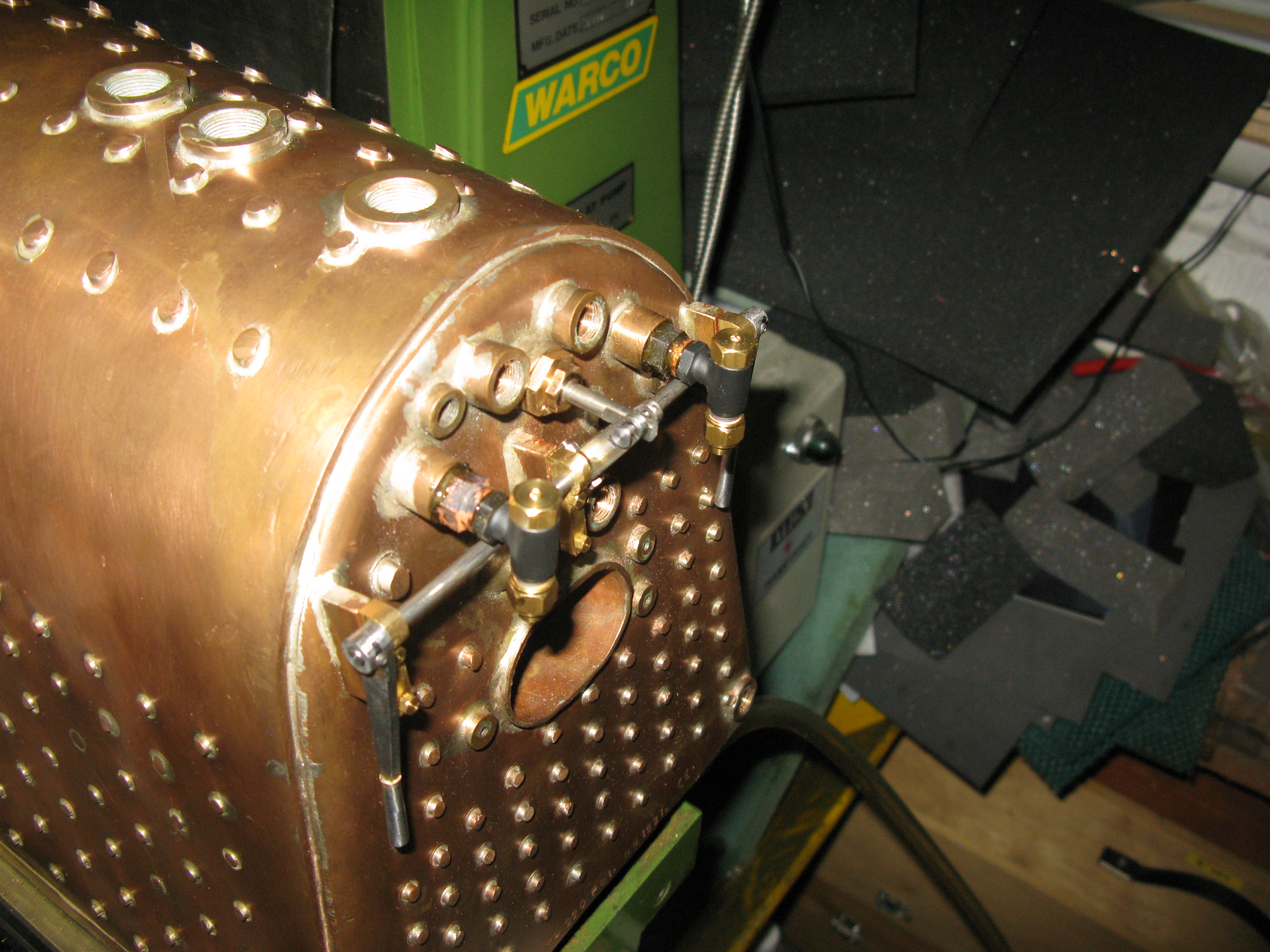
The next job was to start on the wet header connection. This is bolted to the tube plate upper flange.

The connection includes a 3/4″ copper pipe that runs from the regulator valve through the flange into the wet header connection. There are two 2 BA studs to be fitted to the flange to hold the connection in place.
I have a problem to solve here as the wet header connection also includes the snifter valve which screws onto the top through a hole in the smoke box. My boiler is about 3/8″ too long and I have already drilled the hole in the smoke box to the as drawn dimension. This means the snifter valve connection would not be in the right place, it would be too far forward. Fortunately there is just enough room for the snifter valve connection to be moved back on the wet connection providing I make it a smaller diameter. I therefor intend to decrease the diameter of the connection from 7/16″ x 32 tpi to 5/16″ x 32 tpi and modify the snifter valve accordingly. When fitted it will not appear any different.
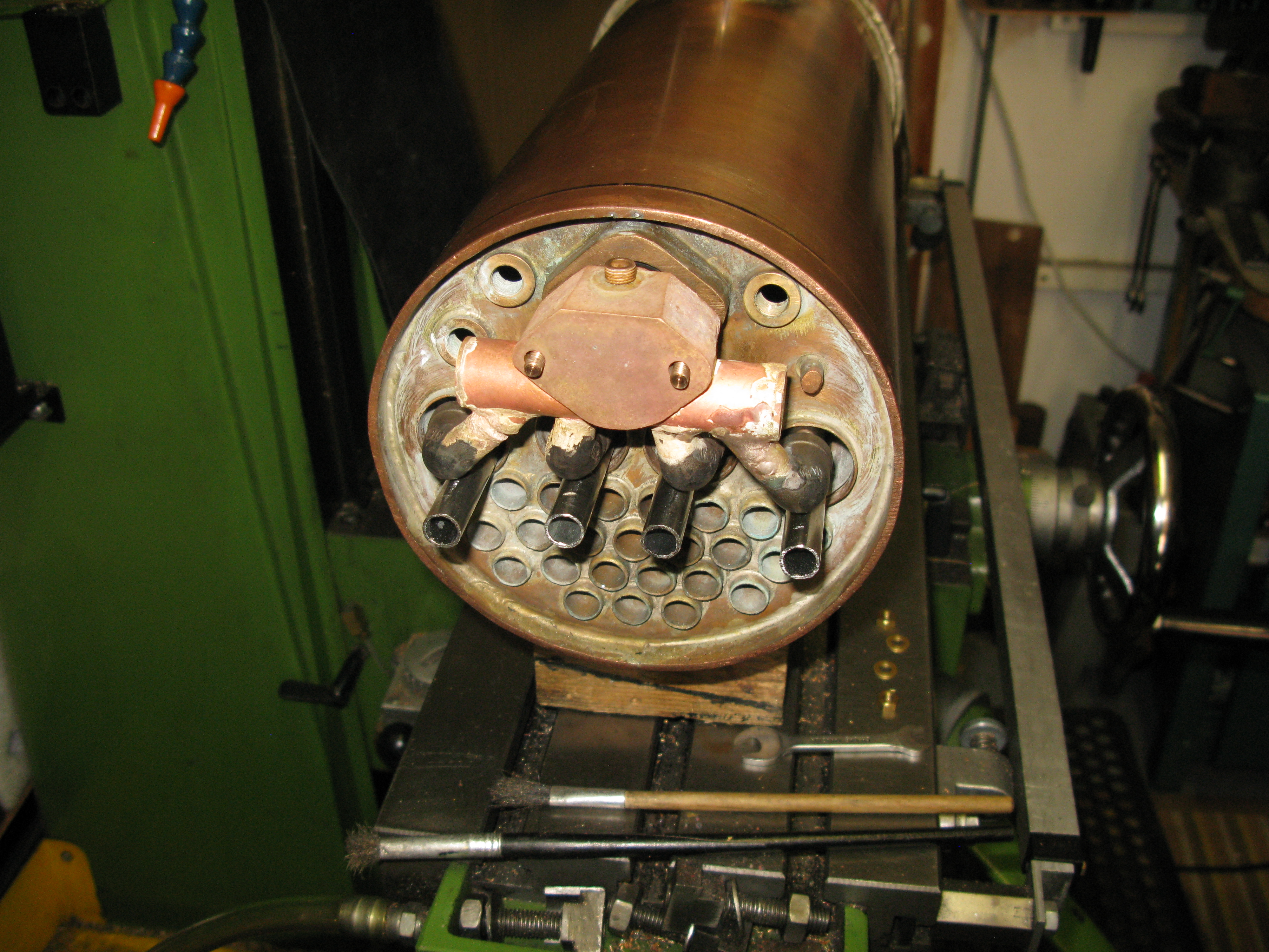
The boiler was made without the fixing holes drilled and tapped as can be seen in the photo. I had an awlkward job to drill and tap the two holes as I have no ability to stand the boiler on end and drill so I had to resort to drilling by hand with the boiler horizontal and using an electric hand drill.
The wet header was drilled with a 2 BA tapping drill and placed onto the boiler and the fixing holes spotted through. The bush is a PB one and therefore not easy to drill nor tap. I cannot claim the resulting holes were exactly vertical to the bush but were close enough fortunately for the wet header to bolt onto with slightly oversize 2 BA clearance holes.
At this stage the wet header still has a chucking piece and has more work to be done on it.
The top of the wet header has to be machined flat and onto this flat will eventually be mounted the fixing for the snifter valve.
The underside has to be drilled and machined out to accept the 3/4″ dia. copper wet header pipe. The chucking piece was removed and the block mounted on the mill table on an angle plate so that the top flat was vertical as checked with a square.
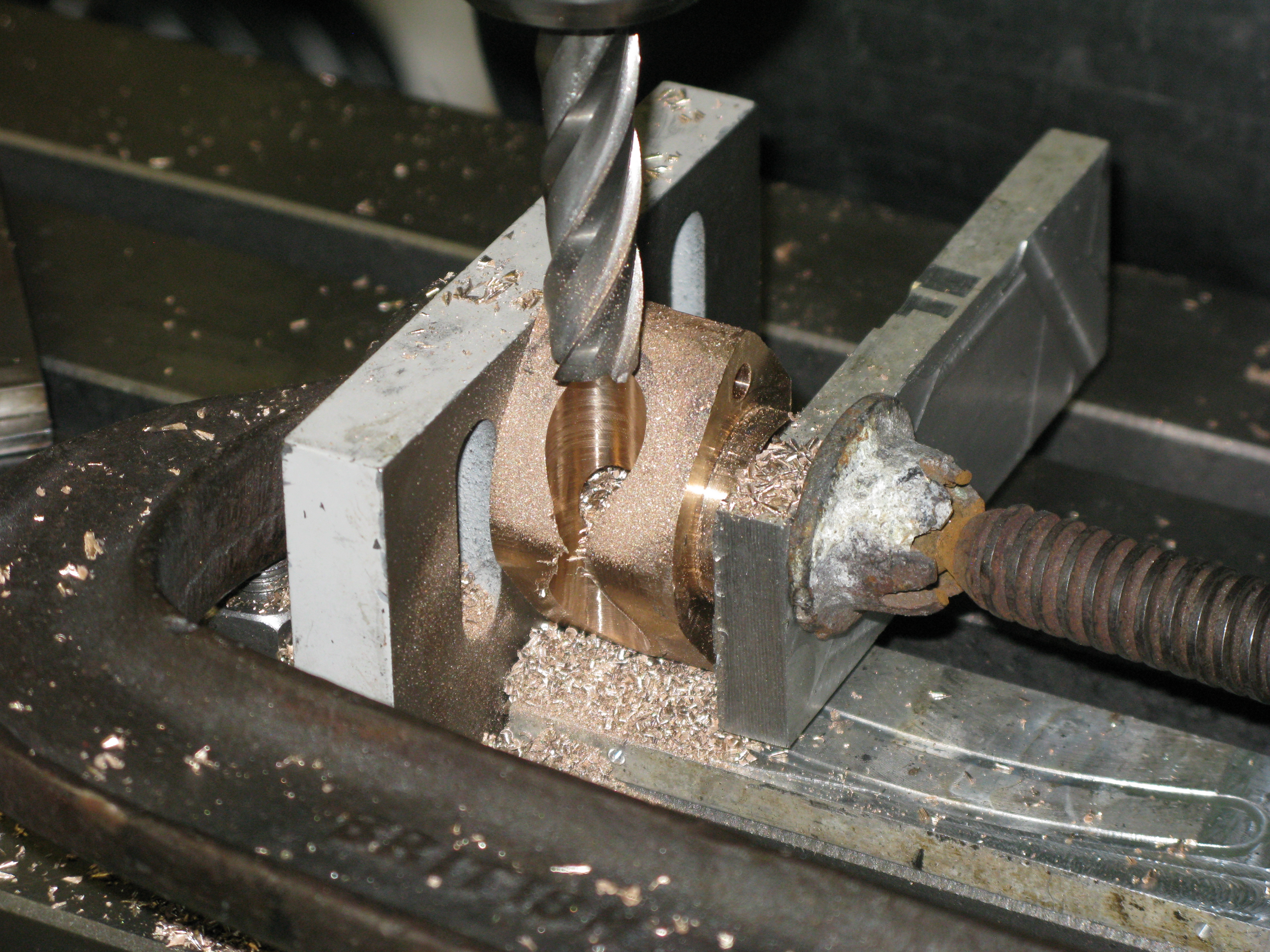
The hole was machined by first using a centre drill to spot the position and deep enough for a drill to enter without trying to cut on a sloping edge. It was then drilled right through and using slot drills and end mills the hole was gradually enlarged to the final cut.

Final size using a 3/4″ end mill

The wet header all soldered up but without the holes drilled for the superheater pipes. My plan is to get the radiant superheaters return bends welded first then I can align the pipes to get the angles of the elbows that fit below the wet header and silver solder them in place. The elbows will be stainless steel and are 1/4″ BSP (from Germany where I found a supplier).
With the regulator valve trial fitted (see below), the wet header could also be trial fitted with the steam pipe in position.

Steam supply pipe screwed into the regulator and finished to length.
The retaining studs are PB and are left over length so two nuts can be fitted to aid removal should it ever be necessary whilst the wet header is in position.
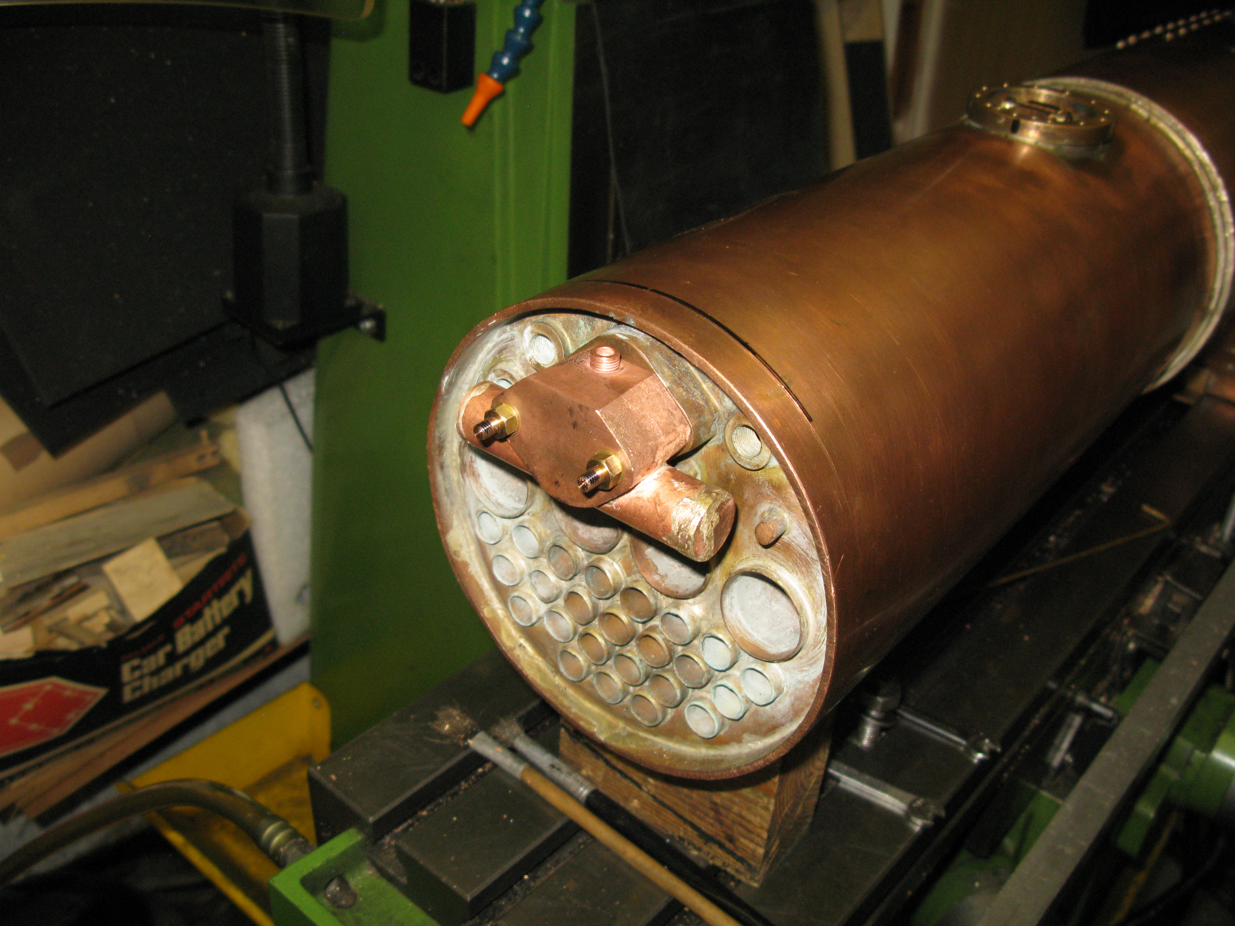
Wet header trial fitted.
The seal around the steam supply pipe and the wet header is not specified and I expect when the design was drawn the use of graphite yarn was expected. I have fitted a pair of 3/4″ O rings in the trial fit above and by the simple expedient of blowing down the snifter valve connection and holding my finger on the regulator valve I could not detect any leakage. Not really a sound test but it shows the use of rings has potential. The final fit will also have sealant btween the wet header flange and is mating boss.
Radiant superheaters.
The superheaters are 7/16 Stainless tubes. At the hot end the drawing shows a gun metal casting to provide the return bend. I was not happy with that arrangement of having a brazed joint of different material in the fire box so decided to make the return bend from 1″ stainless round bar (which I just happened to have). The return bend design allows for the tubes to be recessed into the return bend squarely then the holes for the return bend are drilled at 15 degrees each. (30 degreee inclusive angle).
Drilling the recesses first was not easy and using a slot drill to provide the flat bottom gave me the first sign of difficulty. Stainless (316) work hardens easily and the HSS cutter soon last its edge and after that it was downhill all the way. Eventually I managed to finish the recesses (goodbye cutter) but then had to drill the holes. A centre drill worked OK to spot the beggining of the holes and the first hole drilled with a small pilot drill, lots of lubricant and squealing but it was producing swarf until half way down and that was it, further it would not go.
So I decide to invest in a couple of carbide tipped drills one a pilot (3mm) and the other 8mm. The pilot drill went through fairly easily and the 8mm afterwards was difficult but it did cut, again plenty of lubricant and a slower spindle speed. When it came to drilling the second hole the pilot drill was struggling but was making progress until, bang, progress stopped. The tip had come off. Examination showed that the cause was it jamming on breakthrough into the other hole. Not to put too fine a point on it the solution was to use the broken drill bit as a punch and push the broken tip through into the adjacent hole.
Opening the hole out with the 8mm bit was a struggle and despite plenty of lubricant it squealed and objected all the way. Eventually it bottomed out and the two holes were done.
The drilled block was then put in the lathe to put the 15 degree taper on and it turned as sweet as anything (index tipped lathe tool). All that now remains is to machine the block with flats to make the “spear head” form. I await and index tipped milling cutter to tackle that task as HSS is not really up to the job.
I obviously have a lot to learn about machining stainless.
Well, I have some tipped drills and they do not work as well as I thought they would. But I did find out by trial and error that I had been running the drills too fast. A slower speed (400 rpm) and they cut better and not prone to jamming. Also the tipped milling cutter does not cut as well as the tipped lathe tool does. Not sure why that is but an HSS end mill does the job when run at a low speed (400 rpm).
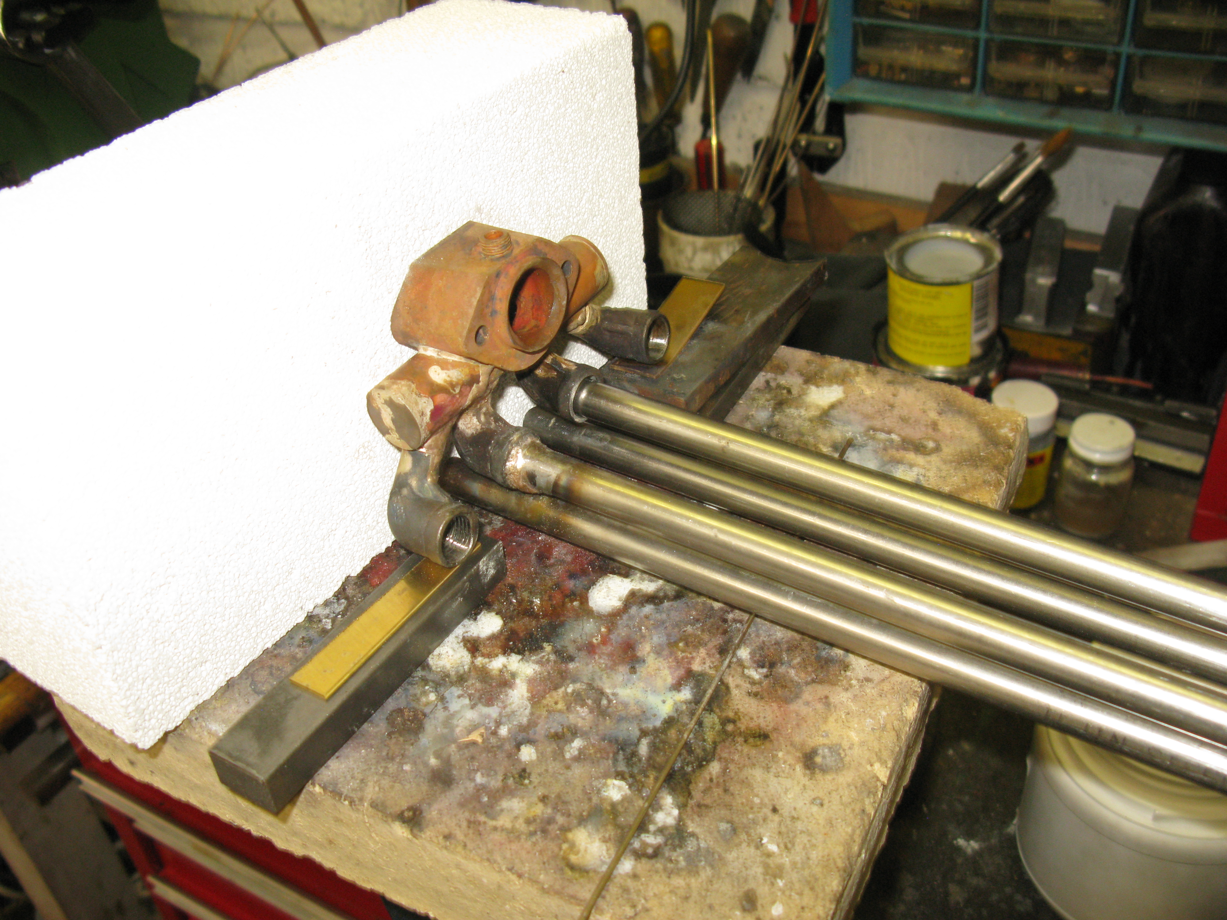
So all four spear head ends are now done and I just need to make a jig to hold the pipes close together and get the return bends stainless welded in place professionally.

Well, I had the return bends stainless steel welded by a company who profess to do stainless steel welding and I had to go back three times to get leaks put right and even then one set could not be repaired. The problem, which to be fair to the company who pointed it out when I took them to them, was the closeness of the pipes in the return bend which makes it extremely difficult for the weld to get into the gap and so it proved. I do not know what welding method they use could be TIG or MIG but I doubt it was gas although peculiarly I think gas welding might have been the better choice as the filler stick is more easily manipulated whilst MIG and TIG need the head to get close to the point of weld.
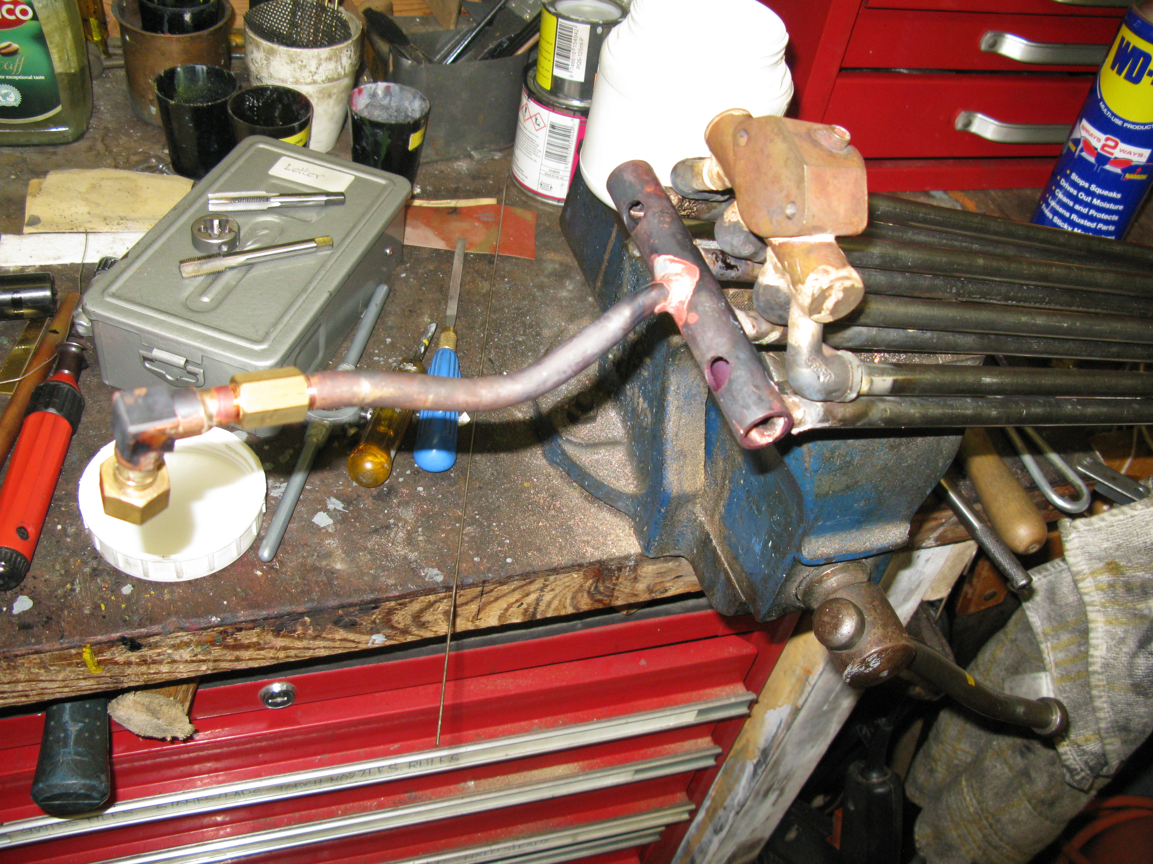
Anyhow, I have to decide how to repair the one set that despite three goes at it, refuses to be corrected. I am thinking about sifbronze over the joint but I only have propane now. My Oxy/acetylene bottles have long since gone back as I had very little call on them and the rental cost were to high for model engineering use. I think with a good hearth and a large nozzle, which I have, I can get the required temperature, some 900 degrees or so. I have little to loose. If it does not work, I just cut the pipes off and start again.
So two days later and the repair using sifbronze has been done ……. successfully it seems.
I was able to get the work up to temperature OK with the help of some newly aquired hearth bricks. At £2.00 a brick the postage was more than the six bricks I ordered.
I intend to pump up the superheater elements to twice working pressure to double check there are no leaks and to do this I shall silver solder an adapter on one both ends with a connection to the pressure tester on one and shut off valve on the other. I have plenty of length to play with so I hope I can remove the adapters onto the next one to test etc.
Well, two of the superheaters have been checked. The one that had already been treated by a sif bronze repair checked out OK at 200 psi. The next one checked leaked so it had to have a sif bronze repair. At 200 psi there seemed to be some dampness around the joint, at 180 psi it was OK. I need to get rid of the flux residue and check again in case it the flux residue that is making the seal rather than the sif bronze and there is a very small pin hole.

Checking a superheater at 200psi
Remaining two superheaters now checked at 200 psi. One OK and the other needed a sif bronze repair.
A problem. Checking that the superheater elements actually all fit through into the fire box in the correct orintation I found one that does’n’t. It catches at the tubeplate joint with the firebox. If it is twisted it will go through but of course when it is fixed to the wet header it cannot be twisted.
Looking for the reason for the obstruction it initially appeared to be a lump of silver solder but closer inspection showed it was the fire box wrapper that was the main culprit. Why should this be? Looking at the boiler construction drawing it is plain that the firebox wrapper is silver soldered to the inside edge of the tubplate flange whereas normally perhaps it would be on the outside. Anyway, it is to drawing but the consequence is that any deformity on the wrapper tends to make it sit further into the tubeplate and thus nearer the tubes, and this seems to be what has happened as some of the other lower tubes are also partially obstructed so a flue brush will not pass right through.
I cannot rectify this build anomaly so the only course of action is to make a spear head element, rather than the arrow head, which will pass through.
That is until a few sleeps later and a thought …….. can the arrow head be made narrower enough to pass the obstruction?
Well no pain no gain they say and I bit the bullet and ground away the top edge of the arrowhead to as near the welded joint as I dare and slid the element into the tube and much to my suprise it slid through OK and more importantly it slid out again. A result!
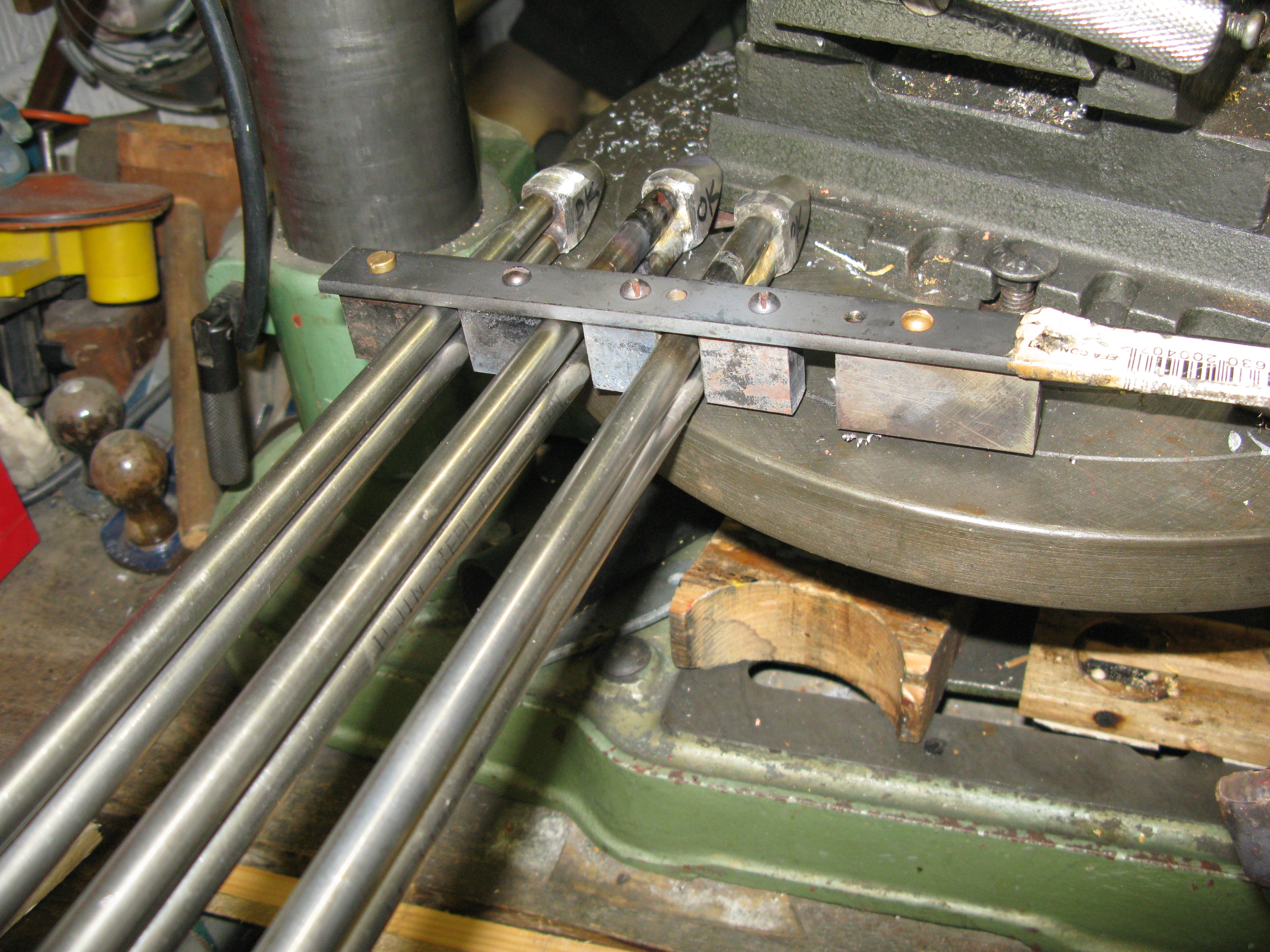
So now onto making a jig to hold all the elements together on the right centres for silver soldering onto the wet header.
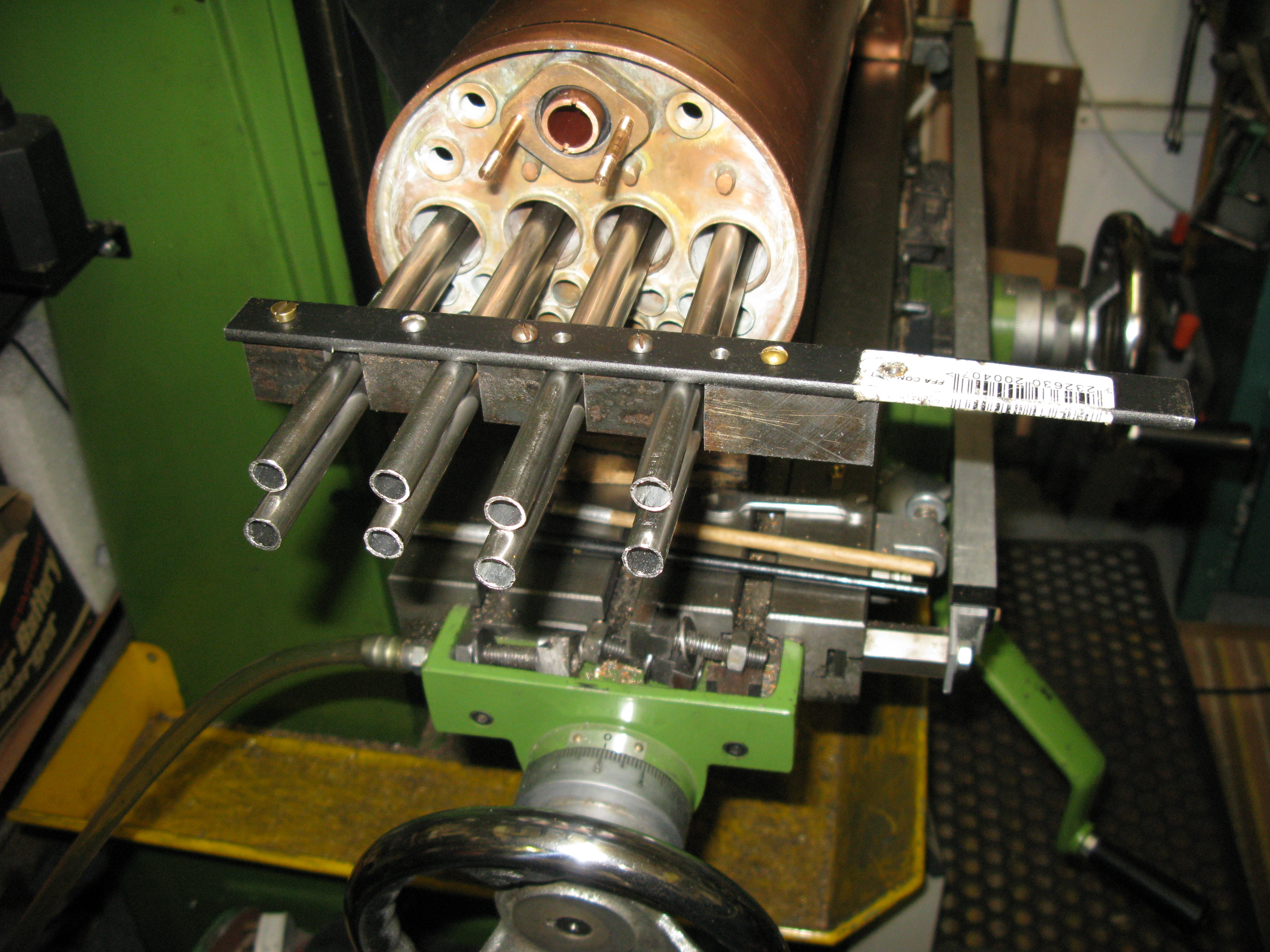
The spacing jig for the elements was just blocks screwed to a bar as can be seen above. To this jig has to be fitted a plate to hold a tube that will fit into the steam outlet pipe hole of the header and thus fix the centre of the elements from the steam outlet pipe. Although not too obvious from the above photo there is not a lot of clearance beween the two elements in the one boiler tube bore which has an OD of 1.125″

The wet header was drilled to take the stainless steel 1/4″ BSP elbows. The angle of the elbows is 75 degrees for the outer pair and 15 degrees for the inner pair, hence the elongated holes.
The elbows are silver soldereed into the wet header using the jig and the inner pair done first using some scrap pipe to align the header on the jig.

With two done the header was trial fitted to the boiler, and then the difficluties started. There is little clearance for the two 7/16″ elements in the boiler tube and although the jig was reasonably robust I thought there was sufficient movement of the header and aligning pipes on the jig for the pipes not to end up so they cleared the internal bore of the boiler tube. This showed itself up as the wet header was slid onto its studs and then failed to slide smoothly over the steam outlet pipe. Fortunately the elbows are threaded so with a lot of internal grinding and numerous trail fittings the first two elements were eventually positioned in the elbows so the header slid into its position studs correctly.
Next came the silver soldering of the outer elbows. These were done one at a time and the same trial fitting and grinding had to take place with each one before all four elements would fit in their tubes and allow the wet header to fit on its studs correctly.

The two outer elements turned out to be at an angle in the boiler tube rather than vertical, hence the outer elbows looking slightly lower than the inner. The reason for this was the wet header length was designed (I think) a little too short and the angled holes come right up against the ends leaving no room to maneouvre to get the correct 75 degree angle when silver soldering them in position
Wet header in position … not yet joined to the elements
Finally with a lot of huffing and puffing and a few curses along the way the wet header was finally in position.
Of course the next problem is to silver solder the elements into the elbows at the right angle, and I am at the moment left wondering if it can be done in position but pulled out a bit from the tube plate.
I decided it was not a practical proposition to try and do it in situ so the elements were silver soldered into the wet header one at a time, and as each one was soldered it was checked in the boiler that it would slide in ( and out!) and the wet header would fit onto its position.
The two inside elements were done first.
Second element being silver soldered to the wet header
The elements were supported so they were level with the far end having the separation jig utilised to ensure the correct gap was maintained. An insulation brick managed a sufficient support to keep the header at right angles to the elements.
Separation jig in use to ensure the correct gaps between elements
Fortunately the position of my pillar drill and bench vice are such that the drill table could be set to the right height to match the soldering hearth and keep the elements level.
The two outside elements gave the biggets problem in getting them to fit such that the wet header would fit in position
The elements both came too close to the boiler tube initially as a 3 thou feeler gauge would not go between them. Fortunately by tweaking the elbows so they pointed slightly downward gave just enough clearance for the wet header to slide in place albeit a bit tight. This resulted in the whole assembly having to be jiggled around a bit to slide out as the arrow head ends tended to catch on the boiler tube plate ends even though I had radiused them to ease the removal process.

All four elements attached but not yet proven to slide in and out of the boiler.
The next job is too tackle the dry header.
The dry header is a 3/4″ dia. copper tube capped at the ends and with the 7/16 holes for the elements on one side and three holes on the other side for the tubes to the cylinders.

Dry header check fitting not yet silver soldered to elements
Silver soldering the elements in position was straight forward. However silver soldering the tubes to the cylinders is not as the length from the dry header to the cylinder tube union has to be exact. A peculiar aspect of the as drawn design was that the elements are shown to enter the dry header above the centre line. I could see no reason for this so put mine on the centre line.
On reflection it would have been an easier job for this assembly to have been done before the fitting of the smokebox as access to the cylinder pipes would have been so much easier and getting the lengths right to the dry header would have been easier too.
Anyway that was not my position so first the three elbows had to be made to connect the cylinder union tube to the tube from the dry header. These were machind from gunmetal round bar.
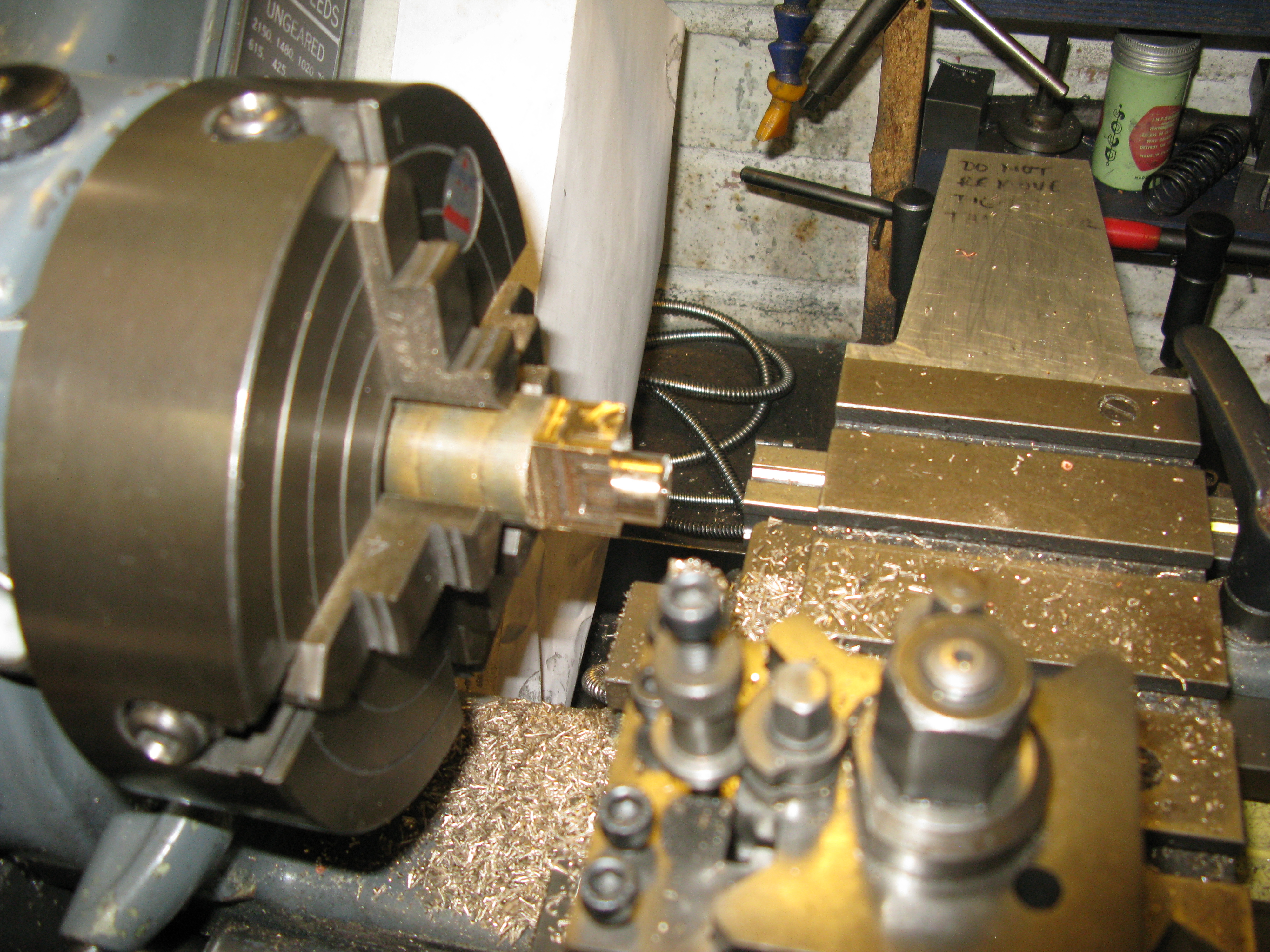
The bar was first machine to give the rectangular outline and then transferred to the lathe to turn the bosses into which the pipe is silver soldered.
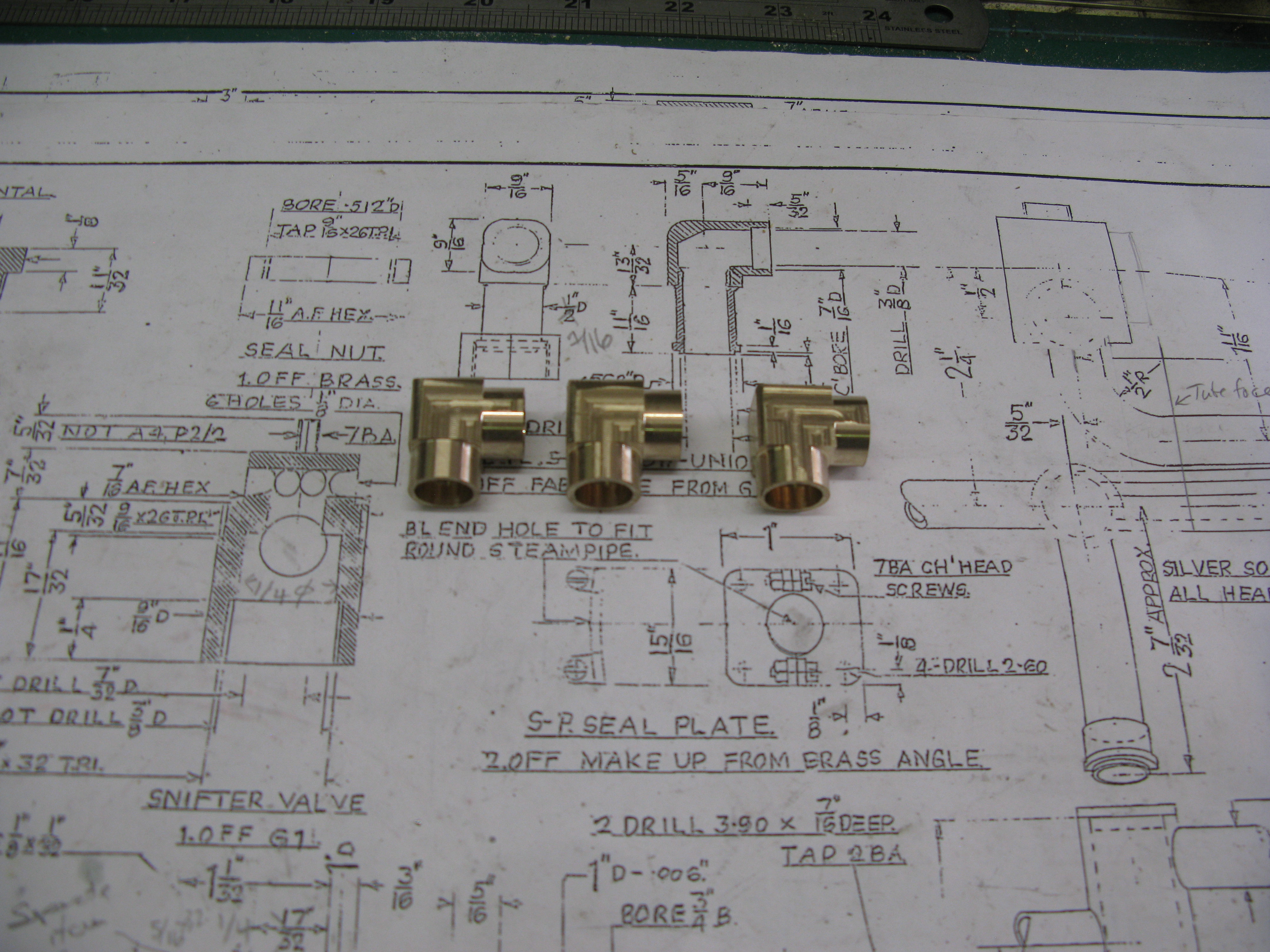
Three elbows completed.
My elbows are not strictly as drawn which shows the pipe connecting to the cylinder being a machine item. Mine use copper pipe silver soldered into the elbow and union nipple which is a flat faced nipple rather than a angled nipple as a flat face is easier to align whne joining and the pipe does not have to be bent (strained) to get the nipple into its socket.
The pipes from the elbows to the dry header have to be offset to get the centres to match. I made a small 7/16″ tube bender to assist in making the offset as hard drawn copper pipe will flatten even when anneald if done without one.

Putting a set in the pipe from header to elbow on annealed pipe.
I was quite concerned about getting the lengths correct between the dry header and cylinder pipes and in the end decided to put a turnbuckle joint in the pipes so with the left and right handed thread the lengths could be adjusted to suit.
The only lefthanded fine thread I could source was 26tpi British Cycle which was just OK with the thread depth to be acceptable on the 7/16″ copper pipe. The turnbuckle is made from 9/16″ AF brass 3/4″ long with internal LH and RH threads just under 3/8″ long with a 1/16″ undercut in the middle where they meet.
Middle pipe with LH & RH thread turnbuckle
The first pipe to be silver soldered to the dry header was the middle one as when the two outer pipes are done the end caps will be silver soldered at the same time.
I found it no easy task to silver solder the pipes to the dry header as with a single propane torch the heat was marginal and the outside pipes proved to be harder than the middle one. Fortunately I do have two torches but not three hands! but somehow I managed.

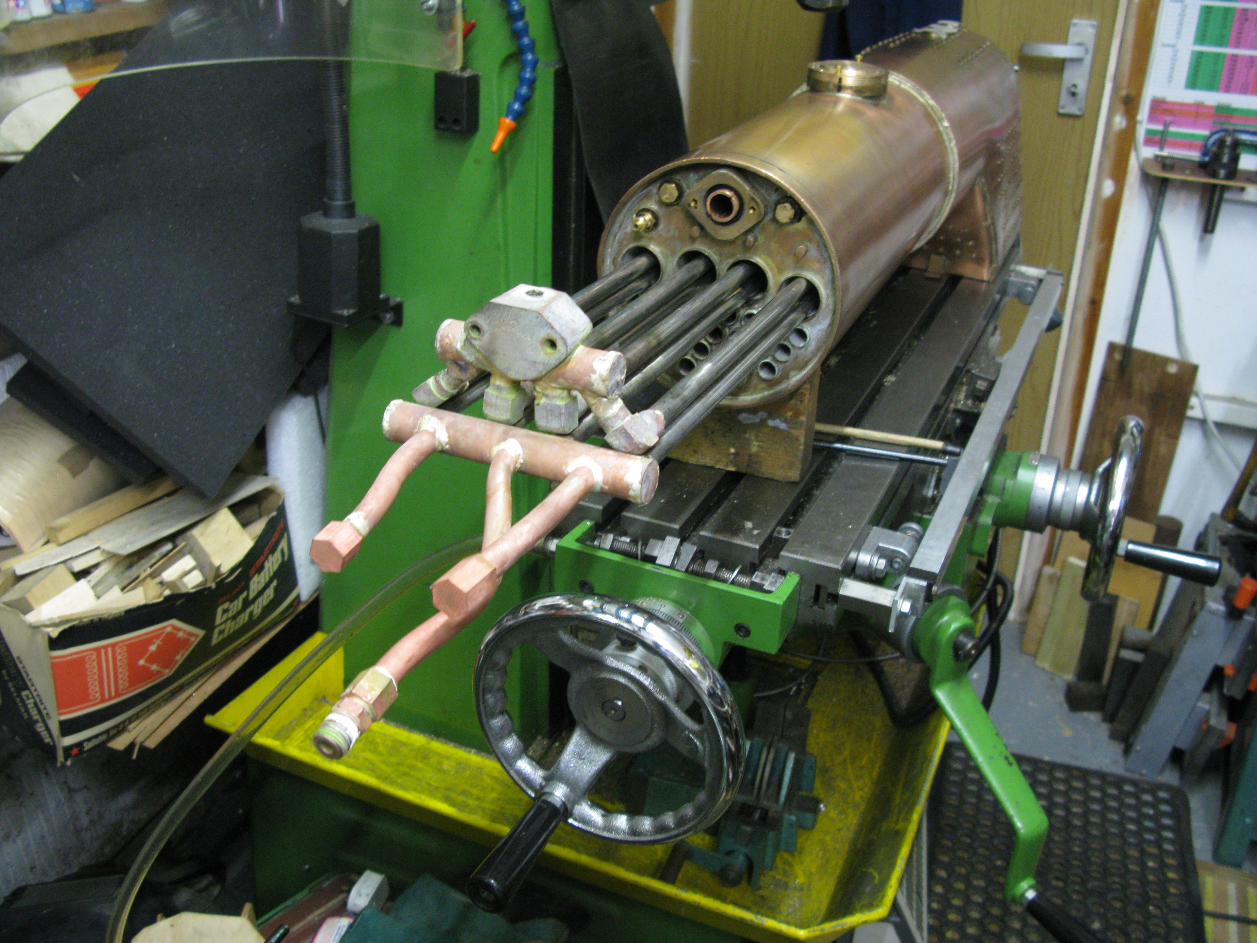
In order to check the alighnment of the pipes the superheater has to be put into the smokebox. Rather than continually lifting the boiler on and off I just rigged up the wooden supports and the assembly could be put in position by aligning the snifter valve connection with its hole in the smokebox. This was close enough as any length adjustment could be taken up by the turnbuckle joints.

First two pipes alignment check in the smokebox

All three pipes silver soldered and the end caps
With all three pipes silver soldered the whole assembly can now be pressure tested to verify all the soldered joints………..
Which turned out to be a failure. The silver soldered joints to the stainless elbows proved to be a significant problem as I could not get a leak free joint. I spent over a week chasing leaks on all four element connections to the wet header and because of their proximity to each other every reheat produced a new leak or did not solve the one I was working on. The silver solder took to the stainless element pipes OK but would take to the elbows. Now I know there is stainless and stainless so I presume the elbows were made from a form of stainless not wholly compatible with silver soldering. So what to do?
I think I am going to resort to cutting off the stainless elbows and either making some gun metal ones or using commercial brass ones. Unfortunately I can find no 1/4 x 1/4 BSP bronze elbows the smallest size seems to be 3/8 BSP………. a decision has to be made.
Well, decision made….. all the elbows have been cut off and unsoldered from the wet header and elements. Looking inside the joints it is clear that the silver solder did not flow into the joints and adhere to the stainless elbow. So new elbows are in the process of being made from Calphos L2 and the jig holding the wet header in place modified to be secure with the elements and in the right place and at right angles to the elements.
The replacement elbows having been fitted and silver soldered in position then gave me a torrid time in chasing leaks. The leaks were not of the large sort but small pin holes or fine short cracks which just weep under pressure. Of course with such close fittings solving one leak inevitably produced another. After a few weeks of demoralising chasing and then a break on holiday which seemed to have worked wonders, for when I came back I was able to solve all the leaks in a couple of days. However I am not too proud of the finished result as there are no nice fillets of solder but quite a few blobs.
The whole process caused me to invest in an Oxygen tank to give oxy/propane. Unlike acetylene which requires you to hire the tank the Oxygen tank is done on a deposit basis just like ordinary propane or butane all thanks to Hobbyweld.
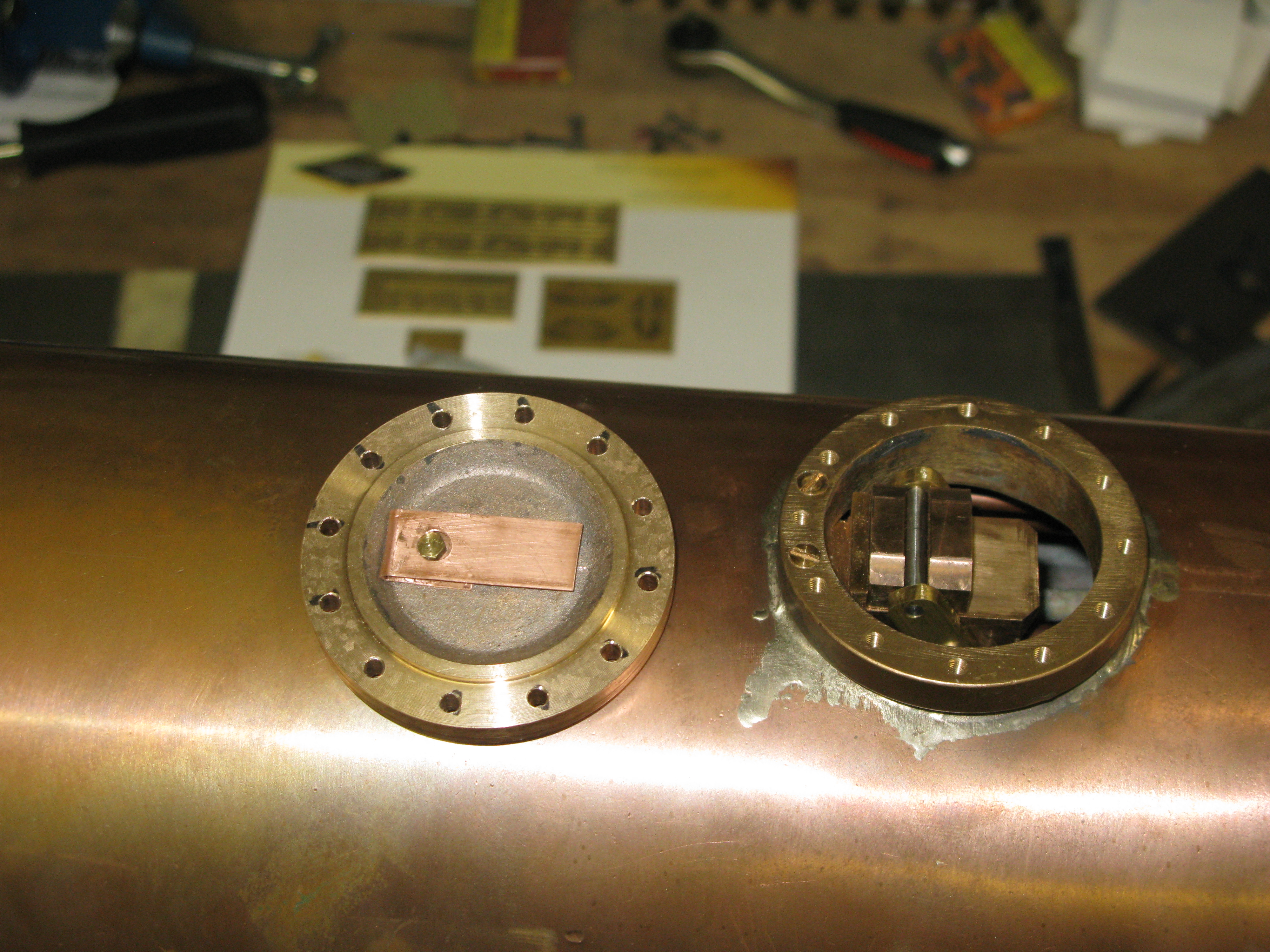
Regulator valve
The valve sits under the dome. As mentioned earlier the drawing calls for it to be screwed to the boiler shell which I am unhappy with and will screw it to the dome bush instead. But to make it first.

The casting is machined to have parallel sides 7/8″ wide followed by machining the top surfaces. It is then drilled at 35 degrees to form the steam entry. I managed to totally get the angle wrong when pilot drilling as I failed to get the wrong reference face set up. Fortunately it does not make too much of a problem but does result in a small hole further forward at the steam exit point into the 3/4″ dia. tube that screws into it.
The correct hole at 3/8″ diameter was drilled at the right angle of 35 degrees.
The problem then was how to bore and screwcut the 3/4″ x 26 tpi thread. The valve could not be safely held in the four jaw chuck as two of the jaws have nothing to clamp onto due to the Z shape. So I rigged up the face plate with an angle plate and clamp as shown below.

This enabled the bore to be done saisfactorily. But to screw cut the thread was a different problem as I did not feel happy of screwcutting into a blind hole under power. So I have ordered myself a kit of parts to make a spindle turning handle for the lathe and I can then screw cut by hand turning the lathe spindle.
So, the spindle handle has been made and it fits well and works a treat.

The long pin acts as a screwing bar which draw a cone into a four split shaft thus jamming the handle in the spidle. The flats on the end are there to enable a spanner to be used if finger tightness is insufficient, but I have found so far hand tightening is quite acceptable and secure.
Turning the spindle by hand enables the screw cutting of the internal thread, which was done successfully.
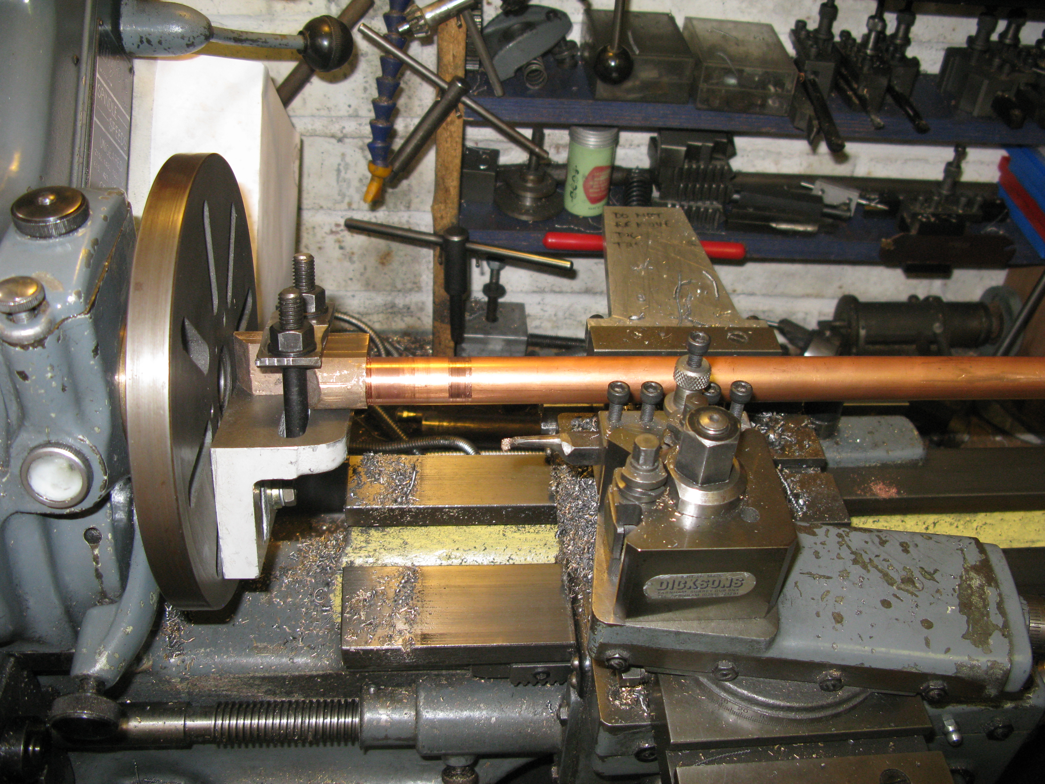
The steam pipe screwed into the valve body
Now I am writing things out of sequence as the steam pipe was screw cut first. Being 3/4″ in diameter means it will not go through the Myford spindle so a steady was used to support the pipe at the end whilst screw cutting.
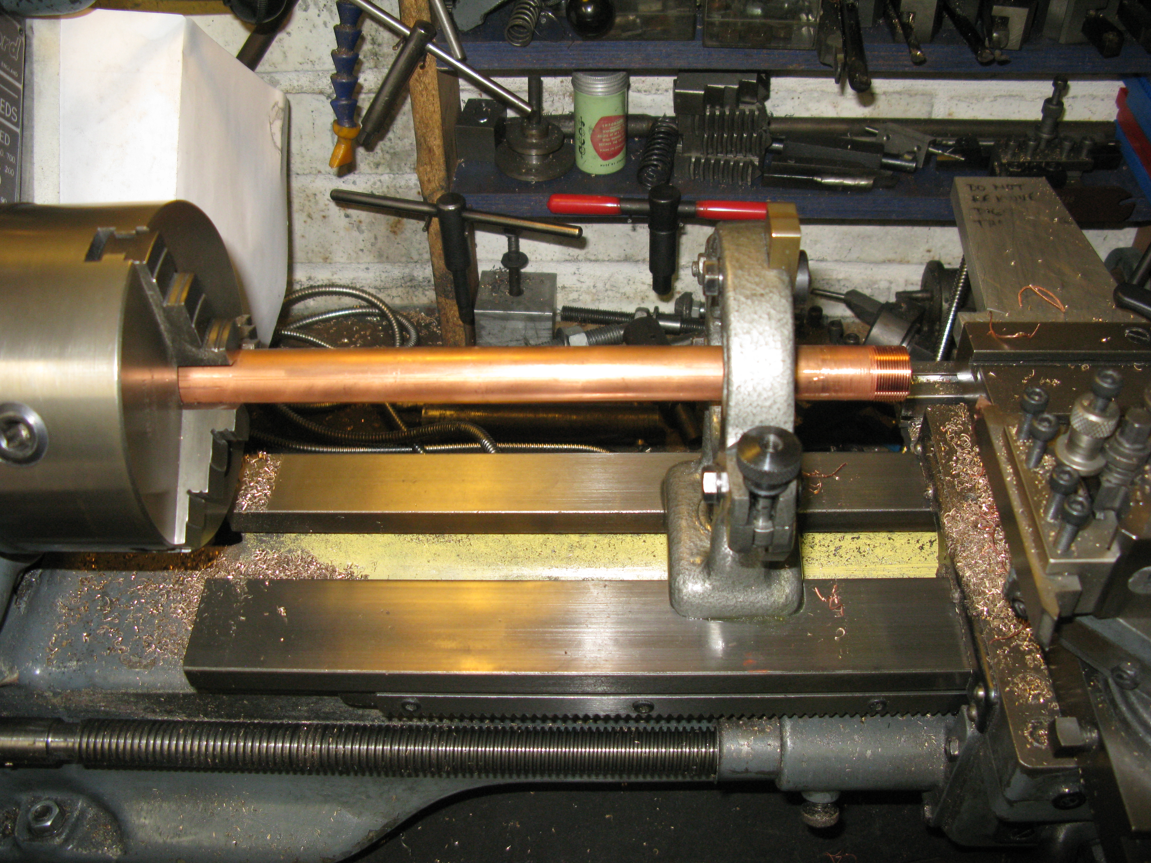
The finished threaded pipe.
The regulator valve is a block of PB with a slot to take the pin that propels it fore and aft. I have made a start on this and its operating levers.
I do have a problem though. The steam exit through the regulator valve body is drawn as a cropped triangle on two of its points. The top point is not cropped and that gives the controlled steam exit as the valve slides back over the triangle. My problem is how to machine this triangular shape through the regulator valve body. At the moment the brain has no solution! All I have at the moment is a 3/8″ dia hole from which to start.
No solution I can think of so hand filing the shape. After many hours a sort of shape has emerged but of course it is tapered as it goes further into the body as no pressure can really be exerted at the file end as its inaccessible.
I did try planning the cropped hole part of the shape on the lathe after hand filing but it was not successful. The tool has to be long and narrow which allows it to spring so not much further forward. A bit more filing and I think I will have an acceptably sized aperture so not to throttle the steam flow..

The operating mechanism of the valve is two links separeted top and bottom by two rods,
The top rod fits into the slot in the valve and the bottom rod accepts the hinge into which the regulator rod screws.

The fixing screw holes are visible in this photo.
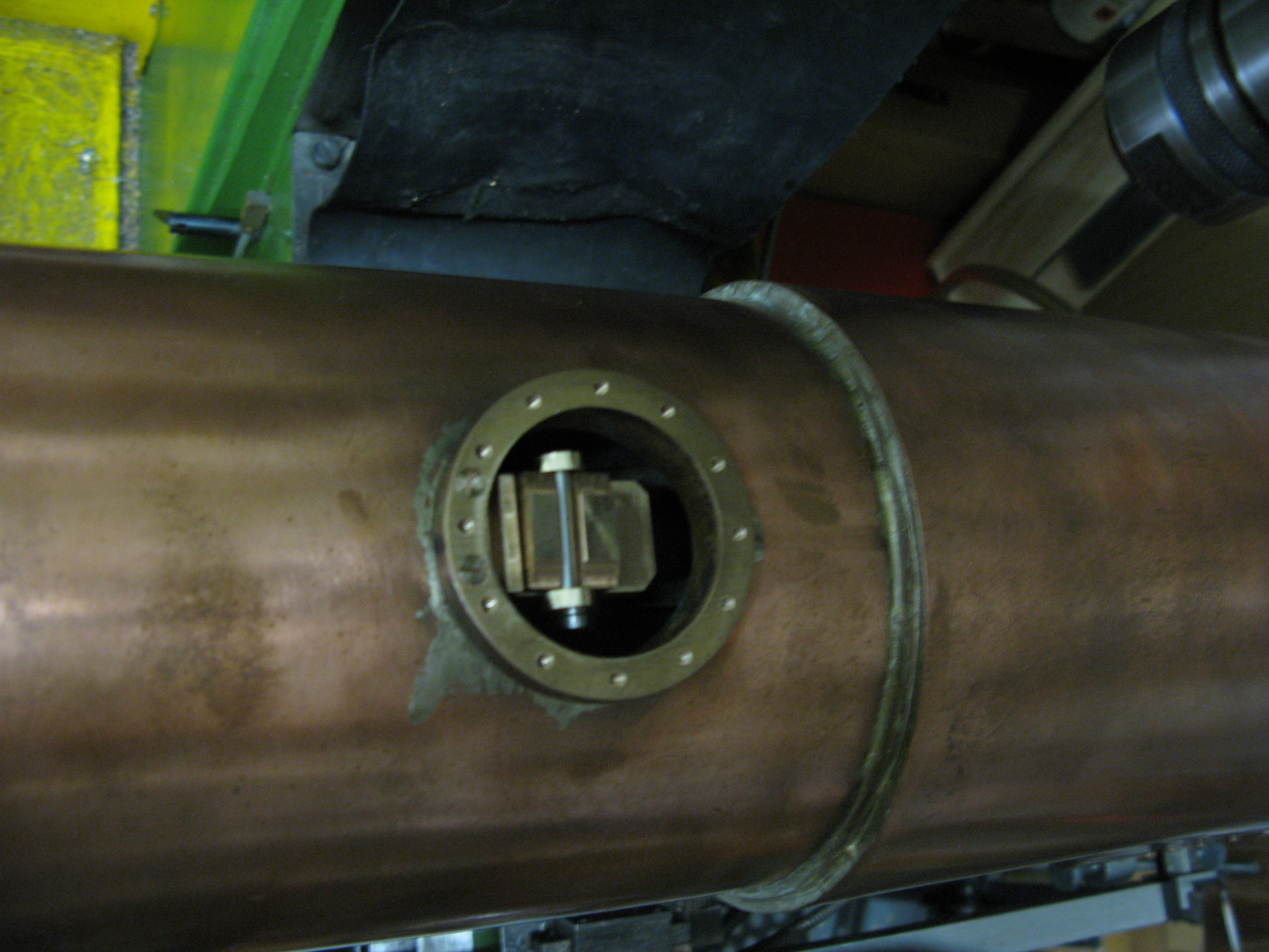
The regulator trial fitted
The two fixing screws (PB) are just visible in the photo above. They are in the dome bush rather than the boiler as I did not want to penetrate the boiler shell and potentialy invalidate the original x2 pressure test.
The gland for the regulator rod in the back head gave me a problem.
The bush in the boiler back head was not as drawn, i.e. it was not a blinded bush into which a gland nut could be screwed with some packing to form a seal around the regulator rod. It was just a plain through 3/8″ x 40 tpi bush. Bearing in mind the gland has to have a 3/16″ dia. hole for the regulator rod that does not leave very much room for a blinded bush and gland nut to be fitted as the wall thicknesses would be very thin indeed.
After lots of scribbles and checks on wall thicknesses I eventually concluded that I could make a blinded bush to screw into the back head and this would have a 9/32″ x 40 tpi counter bore for 5/32″ which would just clear the 1/8″ hex head of the blinded bush without going too deep into the threaded part of the blinded bush as to weaken the wall thickness. The gland nut would then have about 3/32″ to screw onto about 1/16″ of packing to make the seal.
I hope this works in practice!
The rod was initally made long and with a bit of a fiddle screwed into the regulator valve. The purpose of leaving it long was to check the required movement and that the operating lever mechanism would actually fit as drawn.
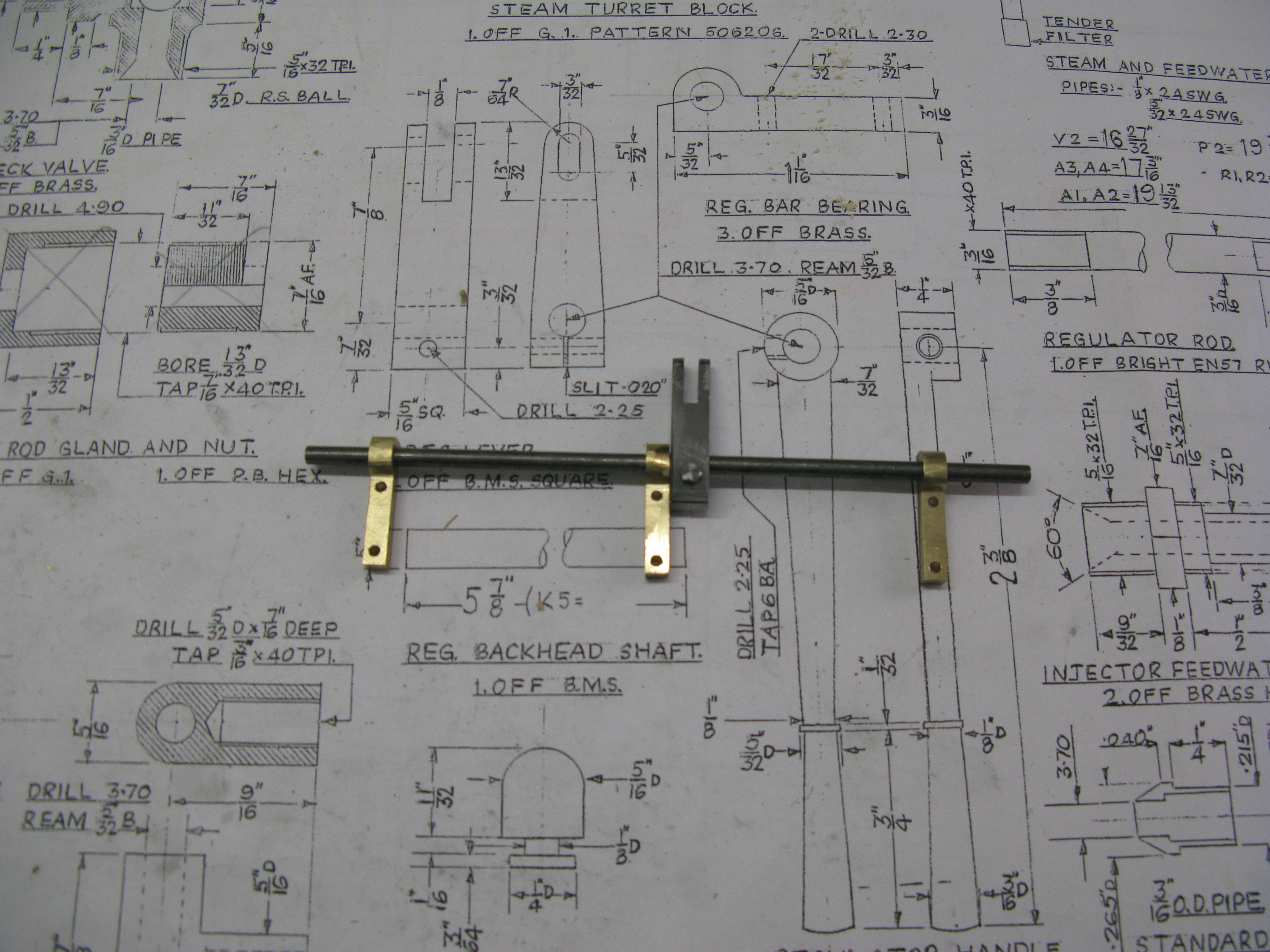
Regulator rod actuating shaft and bearings
So the operating lever shaft and three support bearings were made with the lever that connects to the regulator rod and offering up the assembly showed that the the lever that connects to the rod would not fit. So first of all the regulator rod could be shortened to its correct length now the movement needed was established and the flat put on the end that fits into the lever clevis but not drilled for the pin that connects it to the clevis. The lever shaft was now confirmed as being too long or put another way the clevis was not deep enough for the regulator rod when the full arc of the clevis was travelled, so the clevis had to be filed to make it deeper and the slot for the pin made longer. The whole assembly could not just be lowered to achieve a similar result as the support bearings and their lower fixing bolts were off the bearing support pads. I suppose The bearing supports could have been shortened and new fixing holes drilled but would leave the bearing pad sticking out the top by an 1/8″ or so.
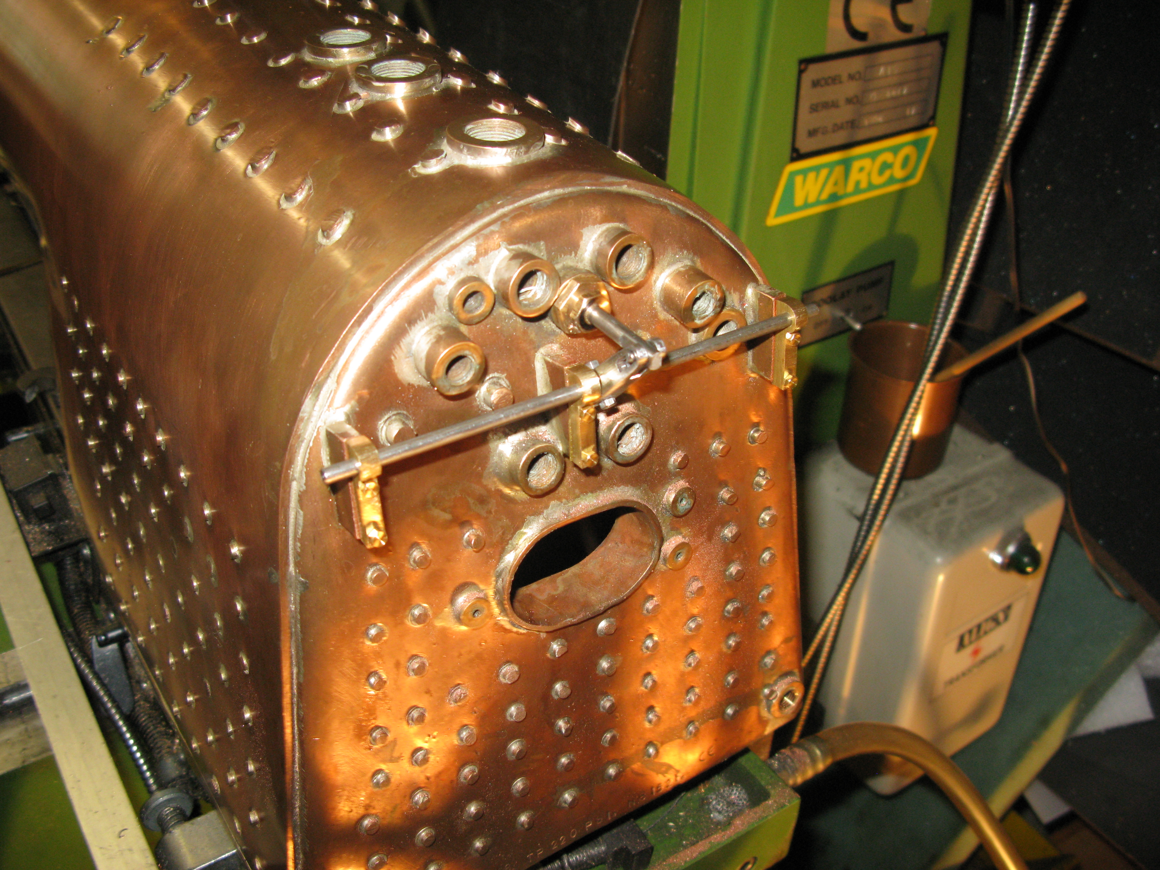
Fitted actuator shaft – handles to come
Having made and fitted the handles and elongated the slot for the pin in the regulator rod I found that the assembly stuck when trying to open the valve from the closed position. A slight nudge on the end of the regulator rod and movement occured OK. Not sure why the interference is there and at the moment my suspicions are the angle between the rod and clevice is too acute. This cannot be made less acute by shortening the valve rod as with the valve fully open the clevis stops just short of the gland nut. Mind you I doubt that the loco will ever need the vlave to be fully open! Needs some more thought.
Decided to shorten the valve rod by 1/8″ and this seemed to have done the trick as it does not stick like it did before so the acute angle was probably the culprit. It is still not smooth on opening so I might take a bit more off as it will not make starting easy if there is any stickyness on opening as the valve would jump too quickly and I would end up with wheel spin.
One of the last jobs on the regulator is close down the dome cover. Before this was done a small copper spring was attached to the underside of the cover to bear down on the valve. As drawn this spring (material not specified) is fixed by a 7 BA screw to the rear of the dome with the screw tapped right through the dome cover! I chose to put the screw in the front, i.e. reverse the spring position which gives the maximumpressure when the regulator valve is closed. I also used a blind tapped hole.
The spring has a hole in its bearing surface through which the retaining srew is inserted to clamp on the underside.
Finally, all bolted down using Heldtite as the sealant.
Feed water tubes and blower tube
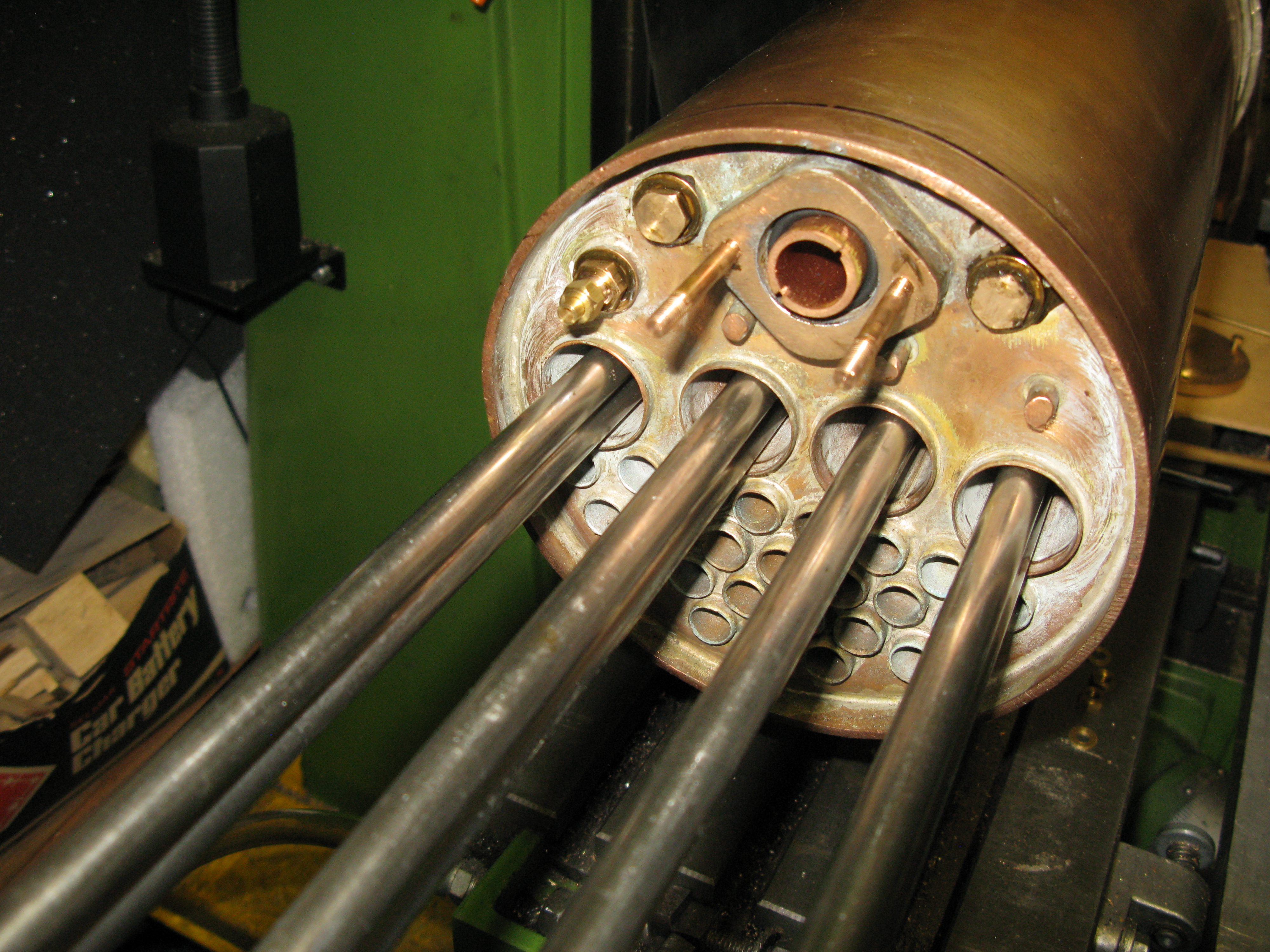
Whilst in the middle of messing about with the superheater fitting I realised that with the headers in place it would be a little difficult to get to the blanking plugs and blower union on the front tube plate especially as fitting the feed water pipes and blower pipe was going to be a fiddley job anyway. This is because all three pipes have to be fed through the boiler backhead bush and finish up in a bush in the front tube plate.
The feedwater pipes (two off) are 3/16″ OD hard copper with two rows of six 1/16″ diameter holes at 6″ from the front tubeplate. This allows the feedwater to have a degree of preheat before entering the water space. and its not a dollop of cold water all in one place.
A bush fitting needed to be made at the backhead end to screw into the 3/8″ x 40 ME bush that would accept the clack valve which is 1/4″ x 40 ME and it has to extend far enough so as to clear the regulator cross rod. The 3/16″ coper feedwater pipe is silver soldered into the is fitting. The assembly is then fed through to the front tubeplate using a hooked rod through the steam dome opening to assist in lining it up with the front tubeplate bush. The fitting to the front tubeplate is a 3/8″ x 40 ME bush with a 3/16″ blind hole to accept the feedwater pipe.

Feedwater clacks and bushes and blind bush for front tube plate
Fitted feedwater pipes and clacks

Blind bushes in front tube plate
The blower pipe is 1/4″ hard copper and has to have a similar adapting bush at the backhead to the feedwater pipes that will accept the blower valve. However the front tubeplate end has to have a bush that will join to the 1/8″ blower pipe that goes to the chimneys. This means the union at the front has to be able to screw into the front tube plate and form a seal onto the 1/4″ copper pipe. To achieve this I threaded the copper pipe 1/4″ x 40 ME as this will match the 3/8″ x 40 ME pitch of the thread in the tube plate bush so the union can screw onto the copper pipe and into the tubeplate bush at the same time.
Blower connection just above the left superheater element

Blower valve fitted
The blower valve has to have a bush 3/8″ x 40 ME to screw into the backhead and a 1/4″ x 40 ME internal thread for the valve to screw into.
Ash Pan
The drawing for the ash pan is difficult to get into ones head as to the overall 3D shape and the sectional views do not make it any easier. Also the grate is shown as per full size with cross bars rather than longitudinal bars with a note that if a drop gate is required cut here! There is also drawn an emergency pin presumably to drop the grate but the shape of the ashpan means that it cannot drop anywhere and it rests on brackets that would prevent it from dropping too. So some design thought has to be put in from the grey cells on how best to get a grate that can have the ash easily removed at the end of a run. Any dropping mechanism is limited to the width of the ash pan doors which are 2 1/8″ wide. If a removeable grate through the fire hole door is used it is limited to 1 3/4″ wide and trying to get the side pieces in position will I think be very difficult in an 8″ wide fire box.
Anyway I have decided to make the ash pan from brass with the front and rear plates 18g and probably the sides too. The drawing calls for brass 20g. I have decreased the gauge as the front and rear plates taper to 3/16″ and I though they may not be rigid enough as will be seen from the photo’s .
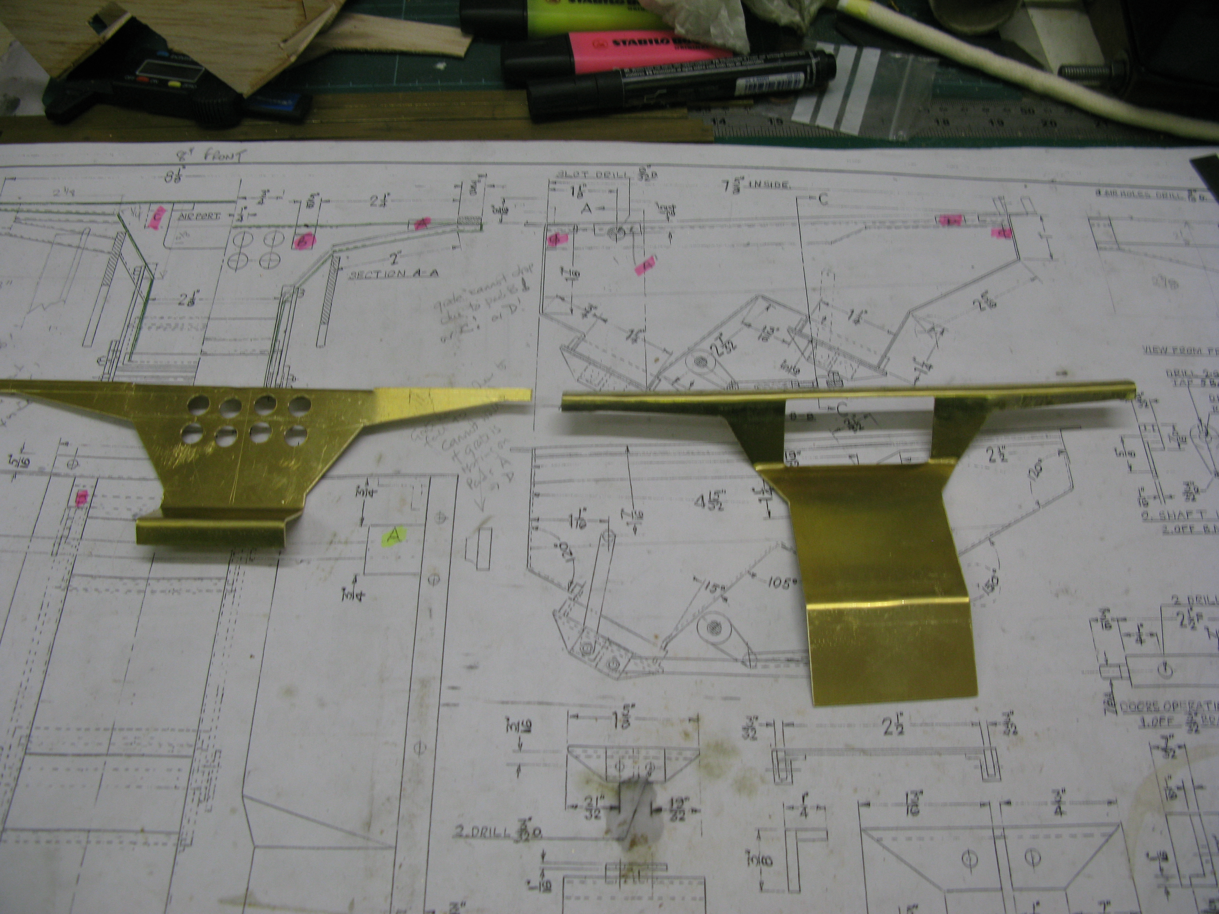
Front and rear plates
I use a scroll saw to cut out the brass shapes as I find that easier to use. Cut speed is slower of course.
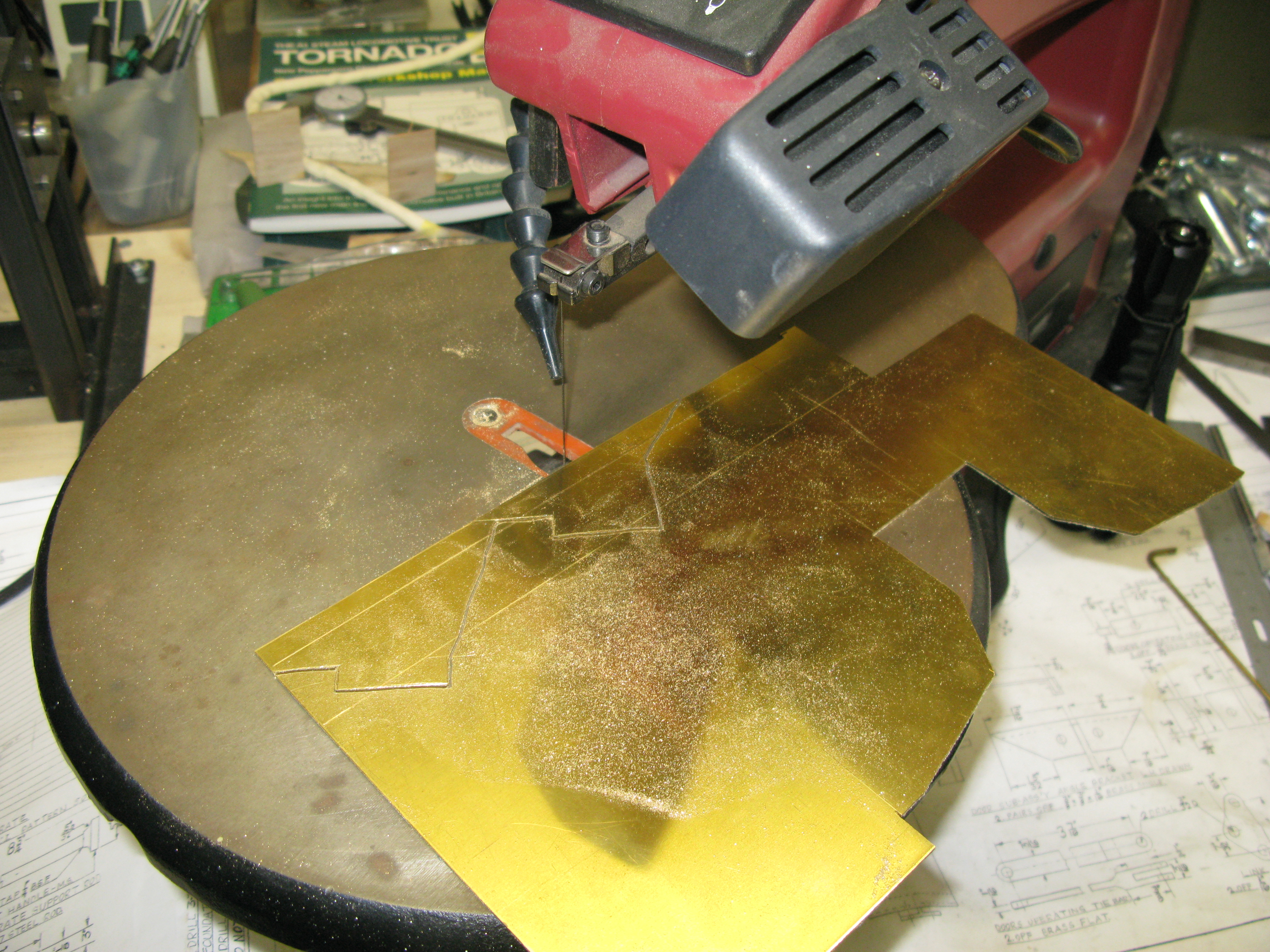
The next plates to be cut were the bottom side plates that form the chutes for the ash pan doors. The two plates were clamped together once one was filed to shape to ensure the second matched the first. They were then silver soldered in place. The shape for the front and back plates and the side plates had to be measured from the drawing as there were few dimensions.
Silver soldering commences

Test fit to check it will fit between the frames lengthwise
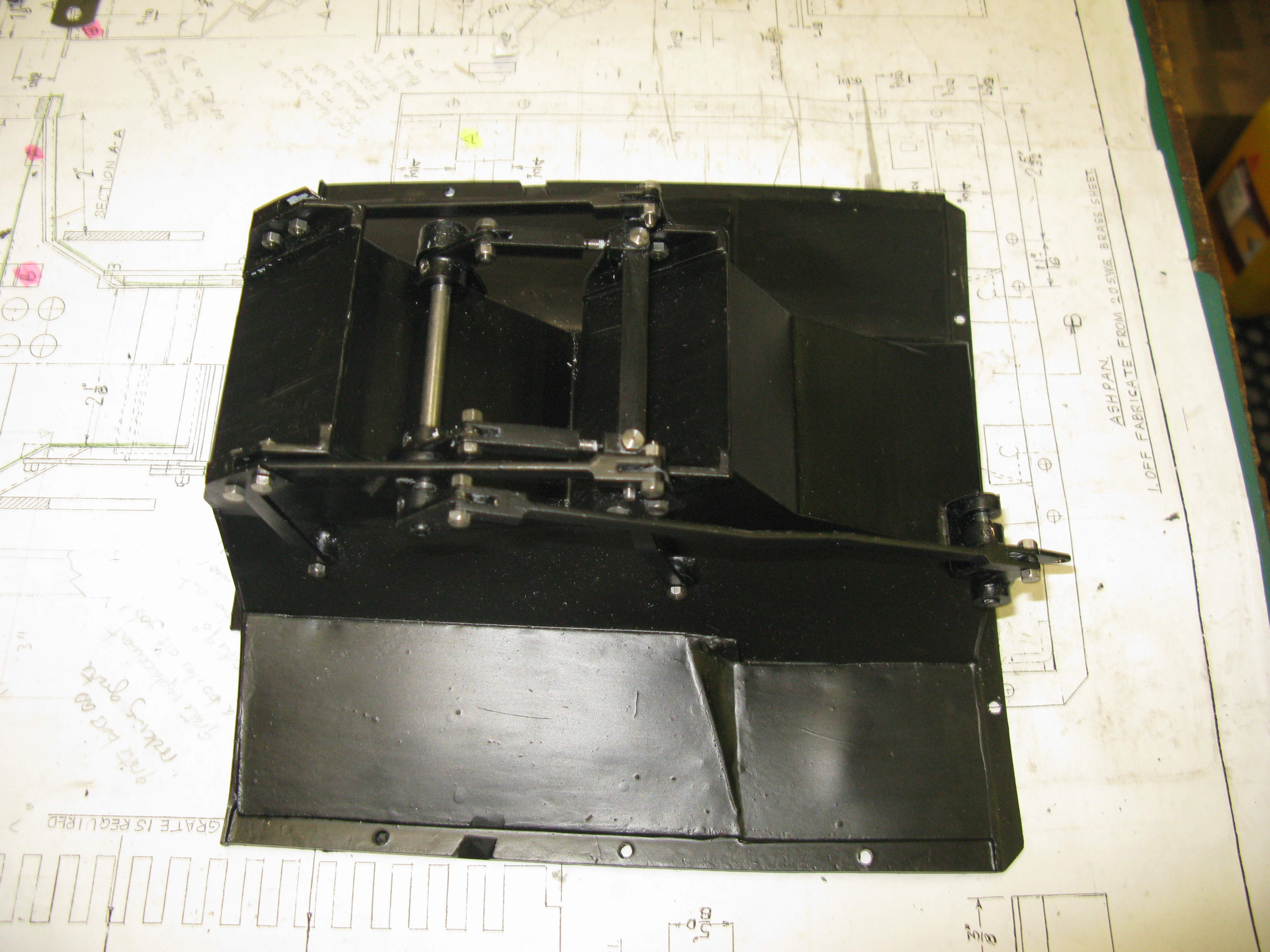
The final ash pan shape is now all silver soldered together and trial fitted in the frames.

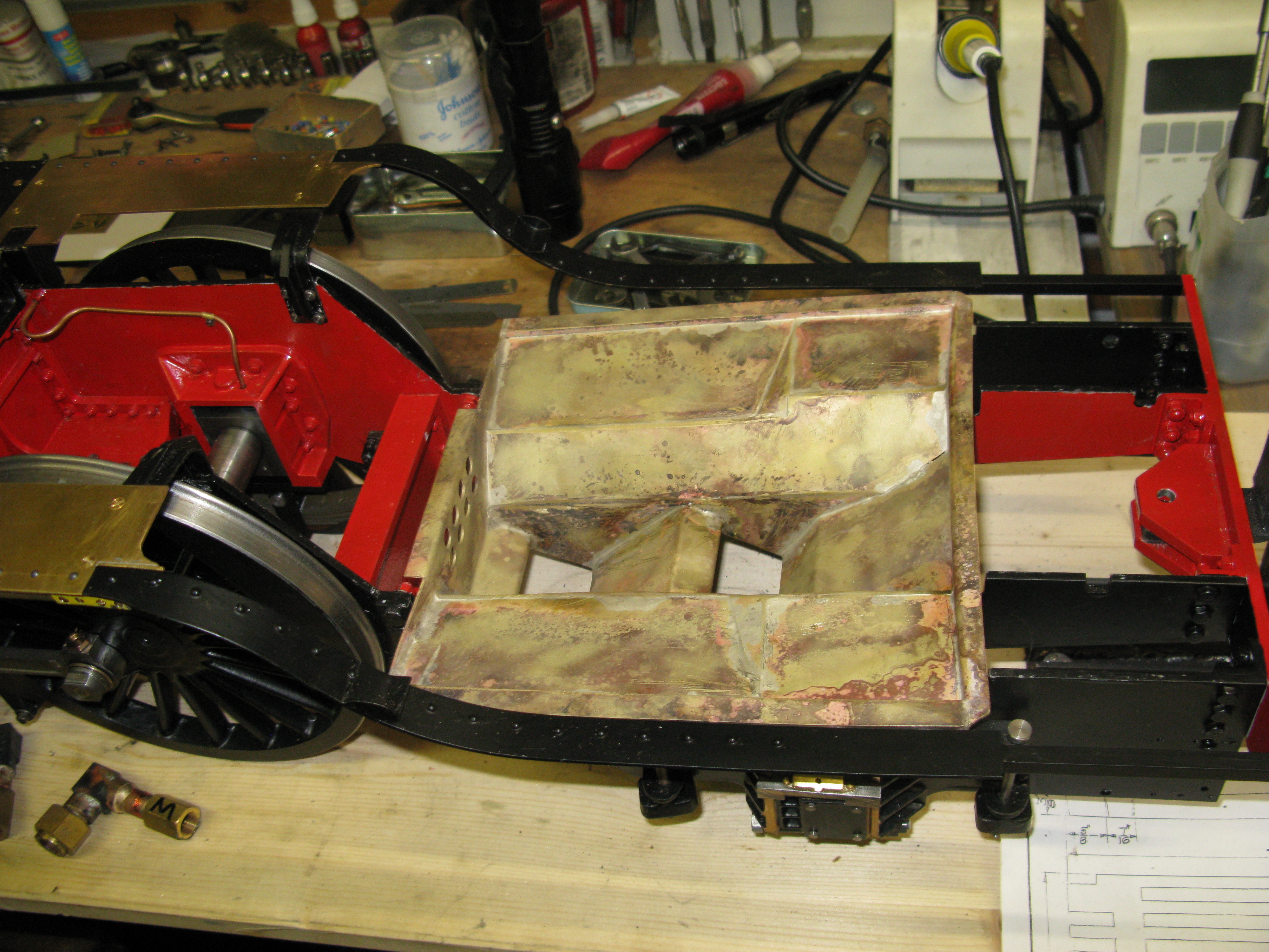
I now have to decide how to manage the grate design. As can be seen from the photo above any grate area at the sides cannot drop as it is too shallow. At best a 2″ wide bit in the centre could drop but supporting it can only be done from the rear of the ash pan as there is no access from the sides due to the frames being in the way. I am toying with the idea of emulating full size and putting in a rocking grate as this would make ash emptying easier at the expense of more complicated engineering. I foresee difficulties in getting the ash at the sides to readily fall to the centre due to the shallow incline. I have ruled out putting a removeable centre piece of grate through the fire hole door, it is only 1 3/4″ wide so maximum grate width would only be 1 1/2″ and the depth of the fire box is large and would make it very difficult to manoeuvre the piece in place. Decision, decisions!
However in-between these deliberations the ash pan doors have to be done. These are plates that swing on levers and the two doors are connected by levers also. A compensating bar connects the lever sets each side and it is operated by a pair of shaft levers mounted on a 3/16″ shaft. But this shaft although shown is not drawn with any supporting method nor is it shown how the shaft is operated to open and close the doors. So a bit of design work to be done. There is also another potential problem. The doors are drawn with a box shaped edge to fit around the chute. It is 1/4″ high. I have my suspicions that this edging will prevent the doors from opening or closing due to the geometry of the levers. So initially I will make the doors without the edging and see how they operate and then decide if the edging can be used.

Ash pan doors and levers
As can be seen in the photo above I have mounted the operating shaft on a pair of brackets silver soldered to the ashpan. The third operating lever on the outside will be used to drive the shaft from a further lever set operated from within the loco cab.

All levers finished
The cab operating lever drives the long lever at the side. Its operating fulcrum is to the right where a U bracket is silver soldered to the ash pan. The bracket has a pair of levers one to drive the side shaft and the other to accept the cab lever. The cab lever is lift to open. It has a few notches in it so the ash pan doors can be set to partially open/shut to act as dampers.
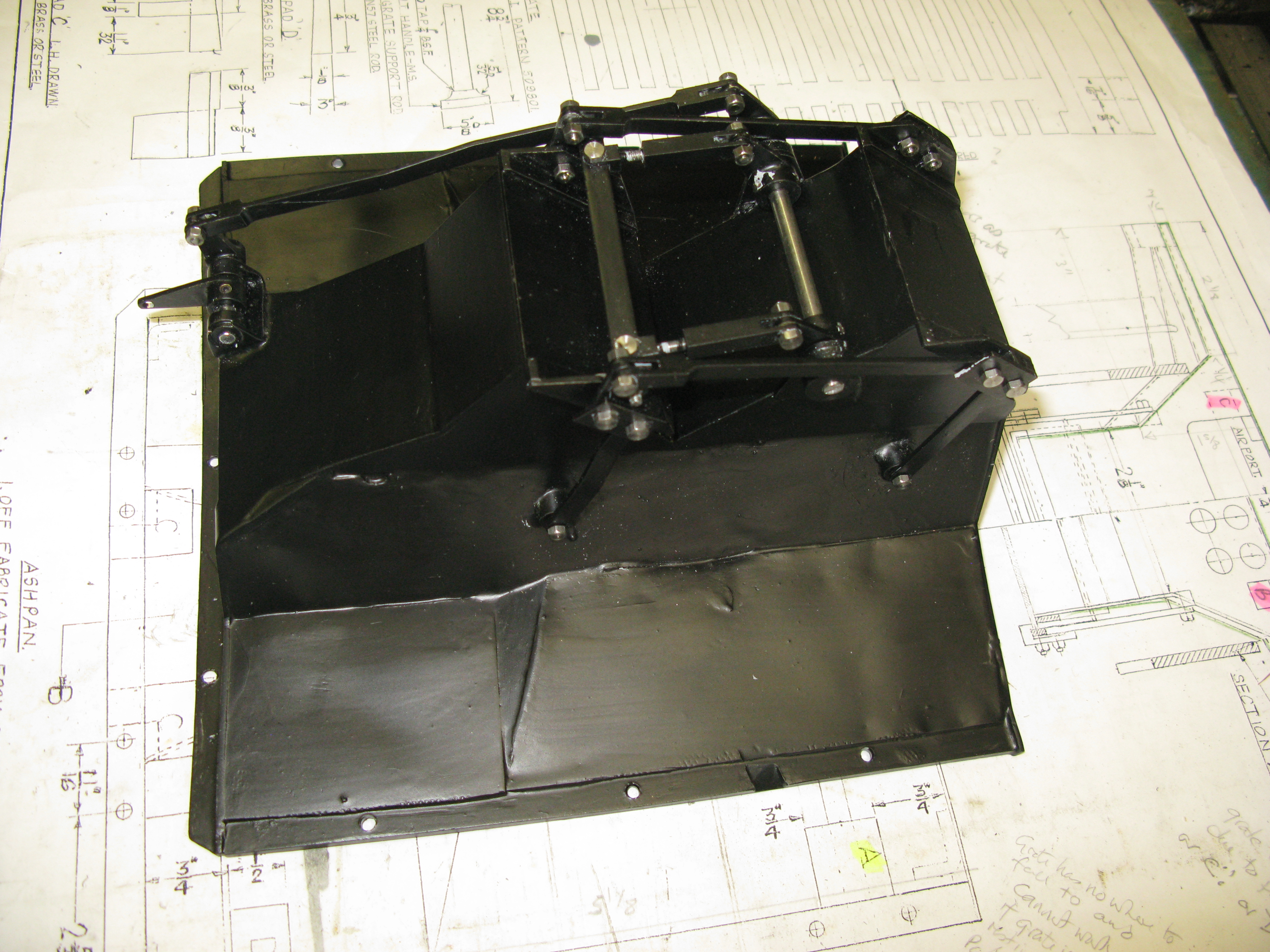
Finished ash pan
The operating lever on this side has had to be altered as it catches on the cartazzi axle. The modification is to make the left hand lever point to the top of the ash pan and a simple bend around the offset so the section from the lever (right) to the offset is now more or less horizontal.
The fixing of the grate to the boiler foundation ring has been somewhat difficult. There is no wriggle room on the grate between the frames and the boiler likewise has to sit at a precise distance from the smoke box to allow the snifter valve connection in the steam outlet flange to line up with the smoke box hole. So to get everything to line up the grate has to be put in the frame and then the boiler mounted on top …… its heavy and is a two person job …… and then the whole loco has to be raised in the turnover frame to get enough room underneath for a pistol drill to spot through the fixing holes. But only a few can be done as the cartazzi axle boxes and springs get in the way of some. However getting three in, one each side and one at the back, is sufficient to get the alignment back with the boiler off the frame so the holes can be drilled and tapped without breaking through the foundation ring which is ony 1/4″ thick it seems. I ascertain this by the distance of the blow down connection from the bottom of the boiler.
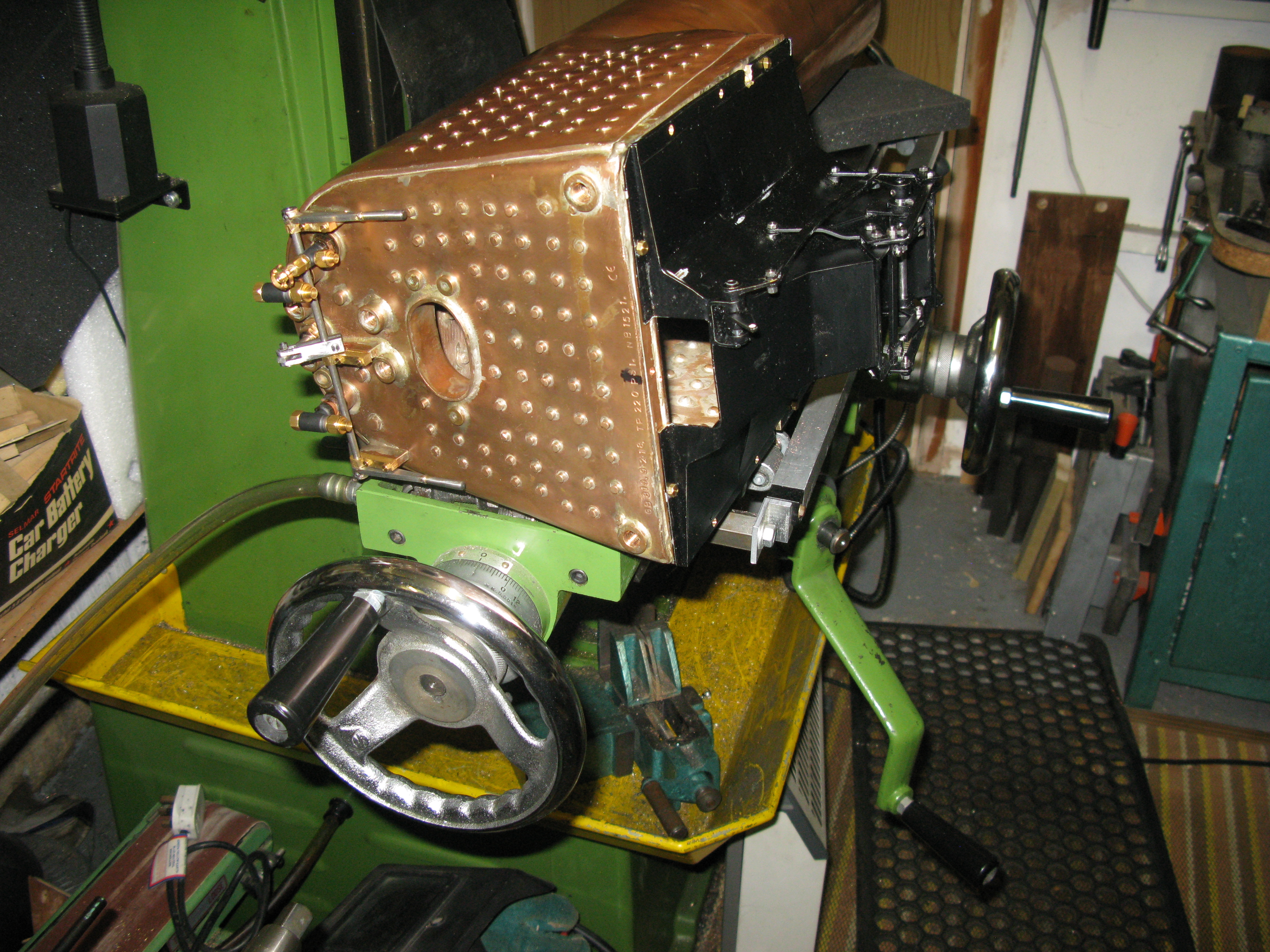
Check fit of the ash pan on the boiler
I have had to remove the section of the ash pan that was above the air hole at the rear as I realised that the actauting levers for the rocking grate need to go through the hole and as the grate is affixed to the boiler before it is put on the ashpan there has to be a gap for them to pass through.
A decision has been reached to use a rocking grate. This has now to be designed and made. It will rest and be fixed on pads on the top of the grate which have to be made and silver soldered in place. The ash pan can then be painted with heat proof paint.
My sketch of the rocking grate design is shown below:

The grate will be in two halves in a single stainless steel frame. The outer vertically drawn sides will have holes into which the grate rocking axle will fit. The other end of the grate has the axle in a vertical slot in the middle bar and the whole bar is covered by a capping to keep the grate axles in place. The axles in their positions will be “sloppy” as an engineering fit will soon get jammed up with ash dust. The grate itself is stainless steel consisting of 4 bars with an operating lever. The axle is off centre to keep the distance of tilt downwards as shallow as reasonably possible. A long operating lever will connect all the grate elements together and be operated from inside the cab. The cab lever is not a permanent item but fits onto a stub lever. This is because it needs to be long to get adequate purchase to operate and rock the grates to disturb the ash and its size is a hindrance in the cab, as per full size.
The sketch shows three fixed bars at the bottom which is due to the stainless grate measurements which are fixed by the available material which comes as a flat grate with all the bars joined in one slab. which has to be cut up into the four bar sections as shown.
The stainless steel grate slab is really quite tough material to cut and cutting up the 12 sections required took a while with a hacksaw. The stainless frame, grate axles and operating levers are all 304 stainless. The levers are 6mm square with one end having a V cut to give the angle when welded to the grate slab (The sketch shows it vertical but it will be angled forward) and the other end having a 1/8″ ( I know mixing my dimensions) slot 7/16 ” long to act as a clevis connecting with the long operating bar underneath that operates the grate slabs. The fixing hole in the clevis is not drilled at this stage but will be done after the arm is welded to the grate slab. His will then enable the hole to be precisely located a fixed distance from the top of the grate slab and all slabs will thus have the same lever geometry.
The grate slab has a 4mm dia. axle which is welded into a slot in each of the slab bar supports. I should explain that the grate slab consists of parallel trapezoidal bars with the longer parallel edge on top. There are then two support bars welded underneath close to the ends but not equally distanced from the ends to provide the slab. A carbide round nose cutter was used to cut the slots with the grate slab mounted upside down on parallels in the mill vice. This ensured all the slab axles would be at the same height from the top of the grate.

Some of the component parts of the grate
The grate frame is actually 15 x 5 mm as this is all I could source in stainless rather than the 5/8″ x 5/16″ on the sketch. The grate slabs being made slightly wider as a consequence.

The main frame bits and blind axle holes in one side coming together.
Note the blind holes is the side piece for the grate axles are near the bottom which means the slots in the central bar (10 x 10 mm) will partially in the main beam and partially in the capping strip (10 x 5 mm) which is now underneath and will be held in place with seven 4mm cap head screws in stainless ( ’cause that is what I could source at a reasonable price!).
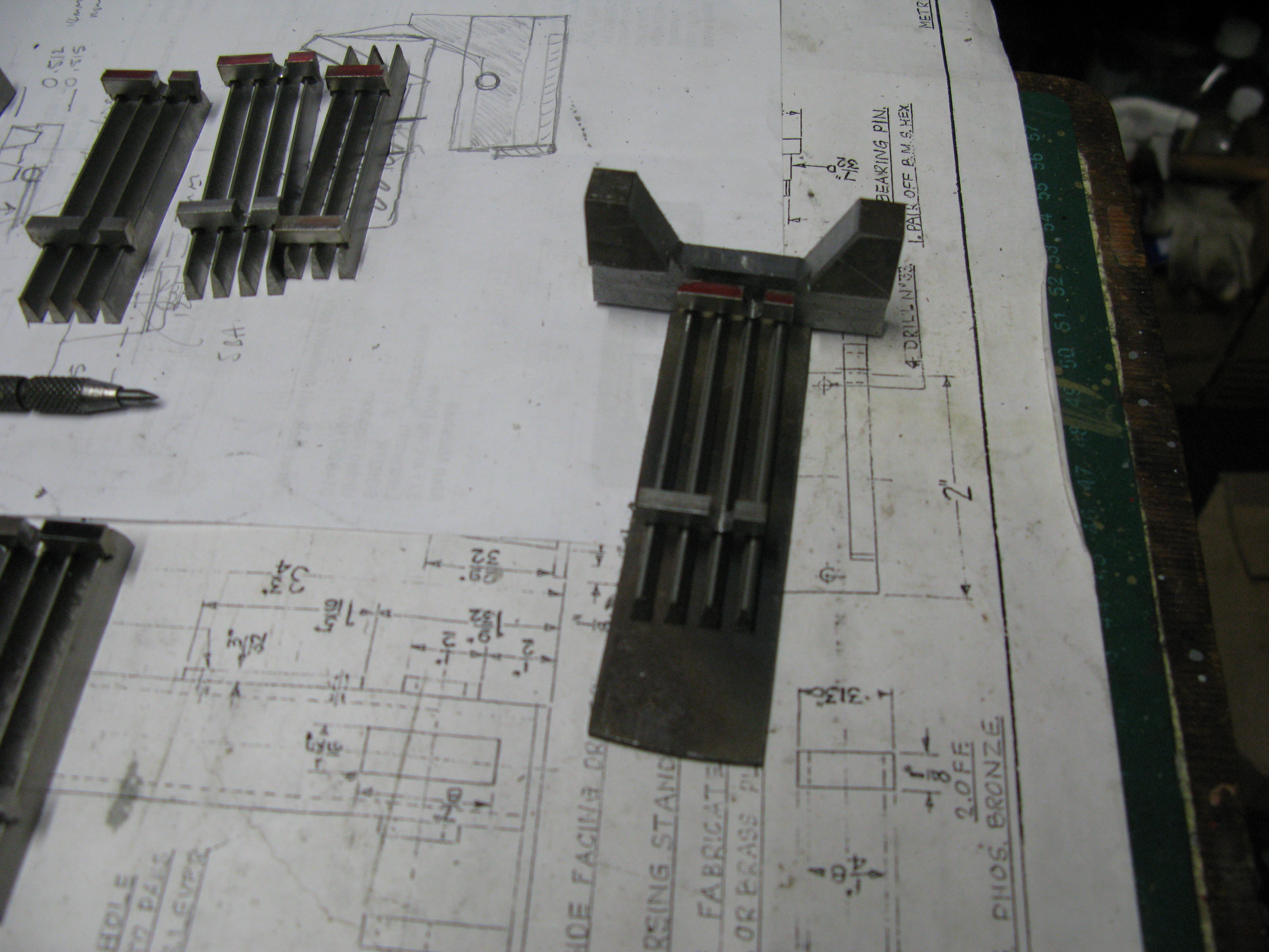
A jig being made to ensure the operating levers are all welded at the same angle.
The grate parts have all been tig welded (a paid for service) and the job of assembly can now start. Fitting the frame into the boiler is the first task and as the grate frame was made to be square it shows up the non square as built boiler fire box.
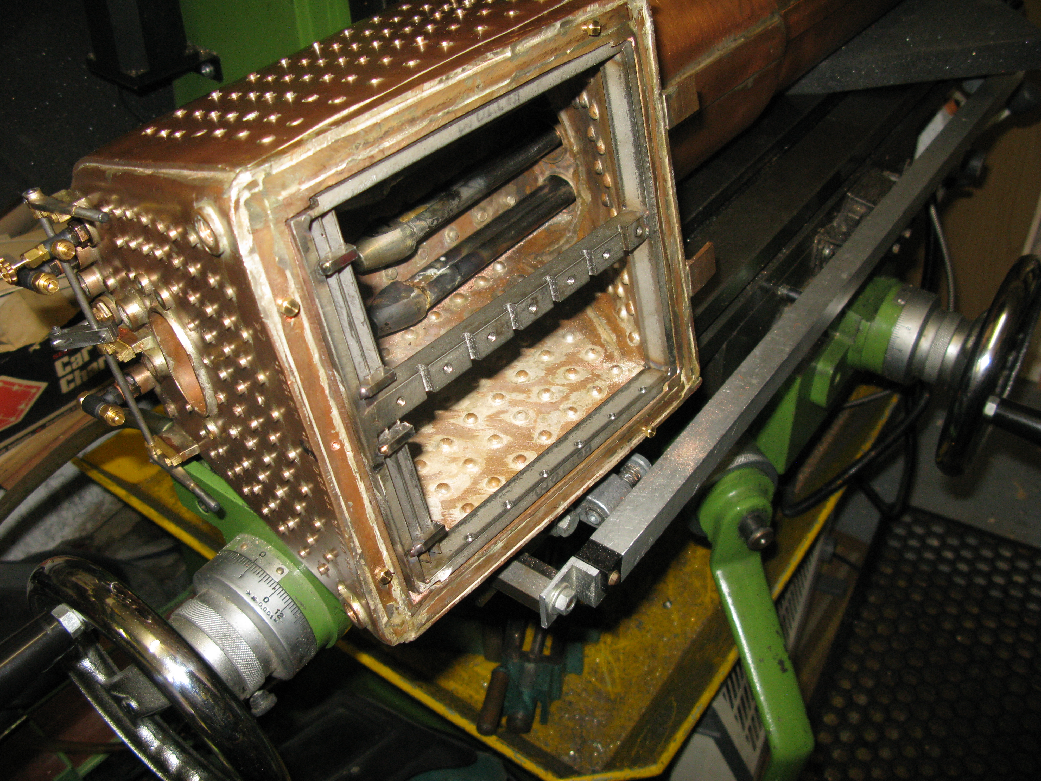
Fitting the grate frame into the fire box
The grate frame is a tight fit in the fire box (will it come loose when hot?) and I have to decide whether or not to provide some fixings. If it comes loose the act of rocking the grate aggresively to clear ash could cause it to move and then jam up the works so to speak. This is a change from when I thought the grate would rest on the ashpan supports and be fixed to these.
Basically it came down to which was the easier for mounting the boiler, try to fit the boiler over the grate or fit the boiler plus grate onto the ash pan. The latter was the chosen especially as the grate frame was a good fit in the firebox.
The sharp eyed may notice the two small three bar sections of grate at the rear. They are permanently welded in place as the dimensions of the rocking elements meant there was a gap at the rear that had to be filled.
The grate is now assembled having machined the operating levers and drilled the holes in the individual grate levers. This was done using the same jig as used for welding as once the jig was set up on the drill press all the grate units would sit in the same place, so providing I did not move the X and Y tables all holes are in the same place. I used a 3mm cobolt drill for drilling the stainless levers as the 1/8″ HSS drill just burnt out.

The grate in its normal position

The grate in its rocked position
From the above photo it can be seen that a slight booboo has been comitted as the front rocked grate has no gap when rocked up against the fixed grate bars . A slight inconvenience when cleaning up! I will see if I can increase the rocking movement to get them nearer vertical. The movement is governed by the amount of clearance of the individual arms in the long operating lever.

The underside of the grate showing the operating levers with temporary bolts in place.
Finally …….The boiler has been fitted to the chassis for the last time………I hope! With the grate finished the last act of connecting the steam pipes in the smoke box can go ahead. The small matter of connecting the blower was done first, this is 1/8″ copper pipe and I put in a circle in the pipe run so that the pipe could be easily located onto the blower ring.
The connection of the steam pipes was not easy. The restricted space prevents hands, fingers and spanners getting to the connections and I had two connections per pipe to make. Firstly the left hand and right hand running joint and secondly the connection to the cylinder pipe. The running joints were sealed using a product called Heldtite which is a liquid sealer, solvent based, and takes a few days to really set properly. If I have done the joints correctly they will be steam and temperature resistant.
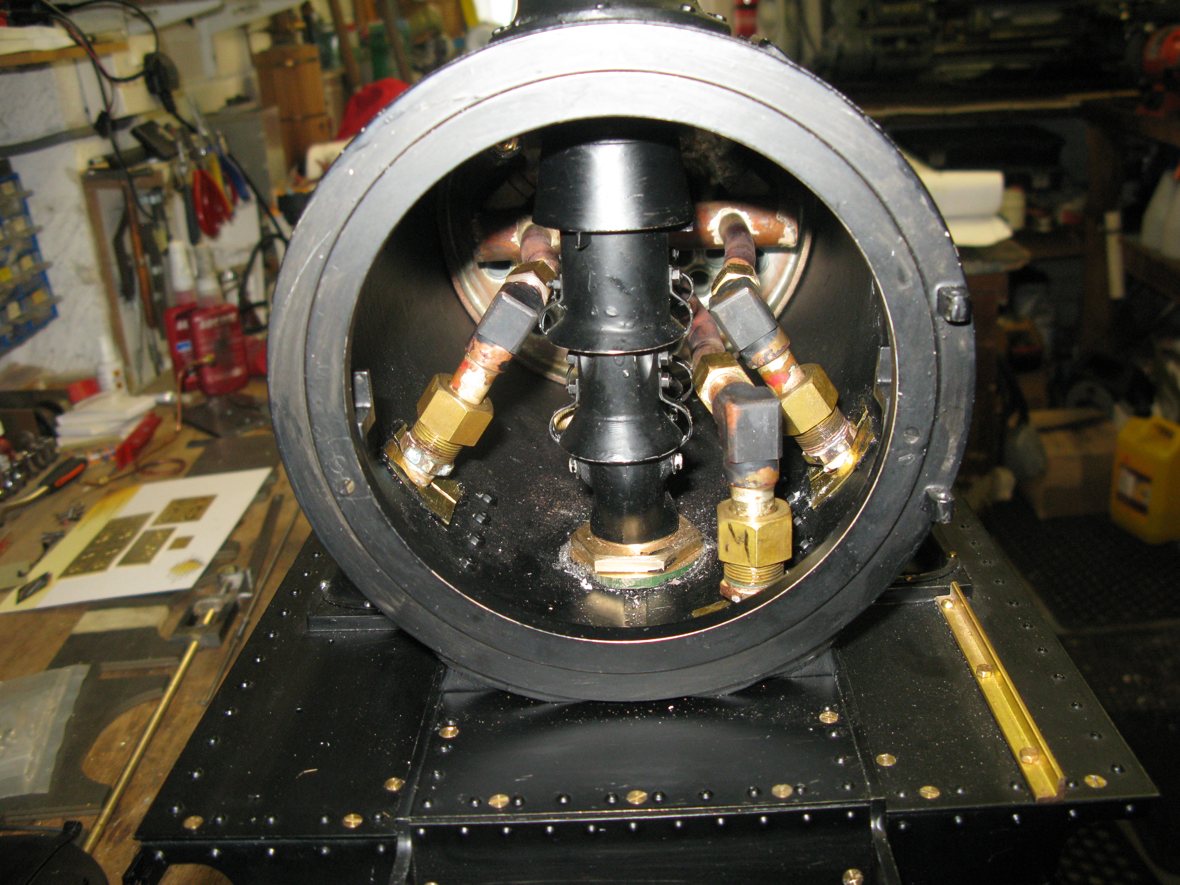
The initial final trial fitting of the pipes (no blower connection at this stage)
Before making the sealed joints I trial fitted the boiler to make sure the LH/RH running joints were OK and were able to position the joining elbows over the cylinder connections. Just as well I did as the two outside ones turned out to be too long and the connecting elbows had to be shortened. by about 3/16″ – 1/4″. With this test done the final fitting could be done.
It took about three hours or so to make the connections in the smokebox apart from the difficulty of space, seeing what I was doing was a problem too. I needed a third hand …….which I did not have, to hold the torch ……. so sometimes it was precariously balanced other times it was held and other times I was working in the dark.
To illustrate the difficulty of working in the smoke box here are the spanners necessary to make all the connections:
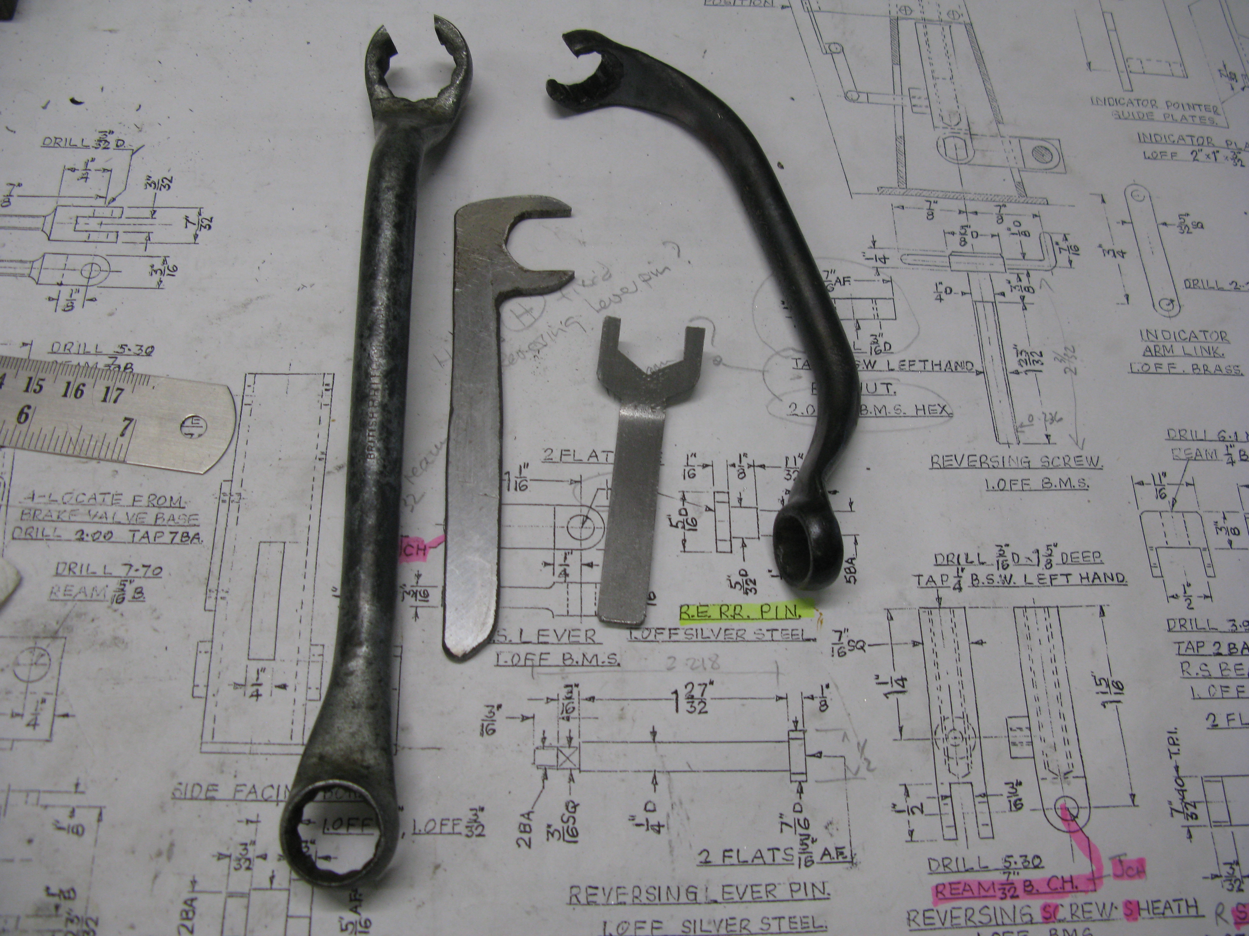
The split ring spanners are able to go over the pipe onto the respective nuts, the funny one on the right is to do the LH/RH running nuts and as these are parallel to the chassis the spanner has to be at right angles to work through the smoke box door opening.
Nothing more to be done other than to wait for the day when I can pump the boiler up with air to see if anything leaks and it all runs . Fingers crossed.
