The cab structure presents a challenge. The drawings are all right up to a point. They are of course drawn in the usual projections but the cab has an angled front section and the as drawn projections of course do not reflect the true lengths. There is a developement of the angled section but I was unsure how good that would turn out to be, especially as it did not appear to allow for the covering over the reversing reach rod on the left hand side and the outline of the actual cladding I was pretty sure would not match the as drawn view.

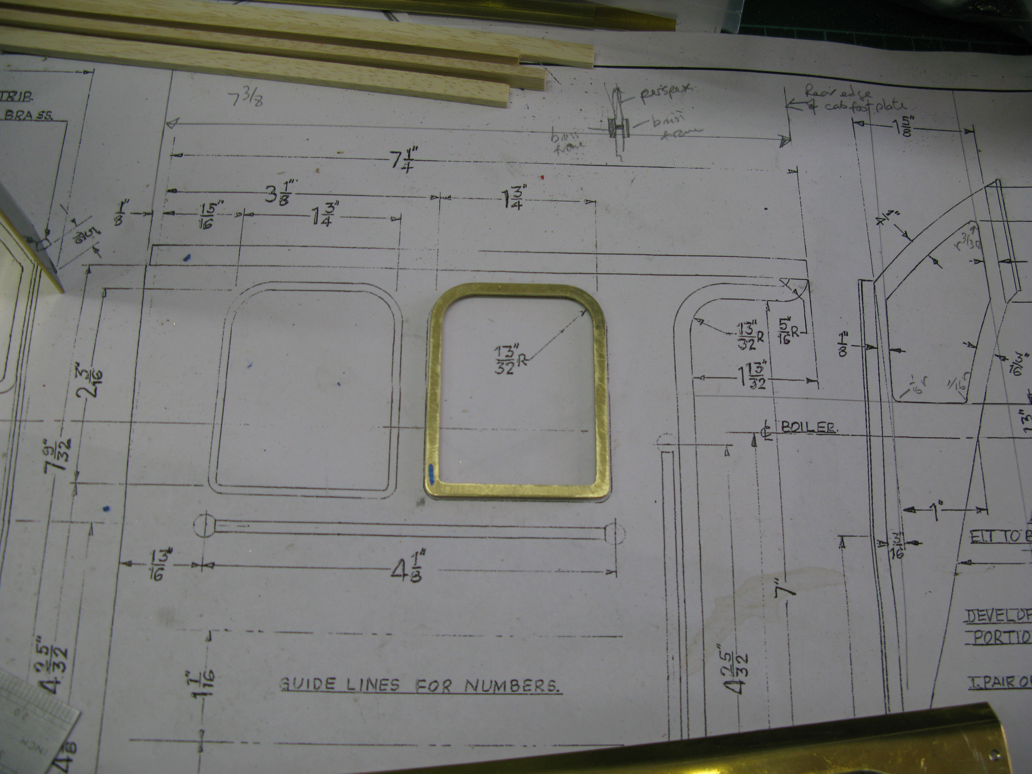
Part view of the as drawn cab structure
The as drawn developed angled part of the cab is shown in the above photo of the drawing.
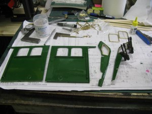
So, I decided on the age old method of cardboard templates to check all the dimensions and outlines.
There are five parts to the structure (excluding the roof ) the two sides, the two angled sections and a front piece. I started by making a cardboard front section and made it to the as drawn outline. This turned out to be pretty close to the actaul outline which I thought was a good start.

Next I did the angled section which was no where near right. Quite a bit of fitting was needed to get a reasonable fit to the cladding and over the cover for the reach rod. Squares were used to ensure I was fitting the template correctly. To get the angle correct I made a cardboard template to the angle that can be seen in the bottom right hand corner of the drawing.
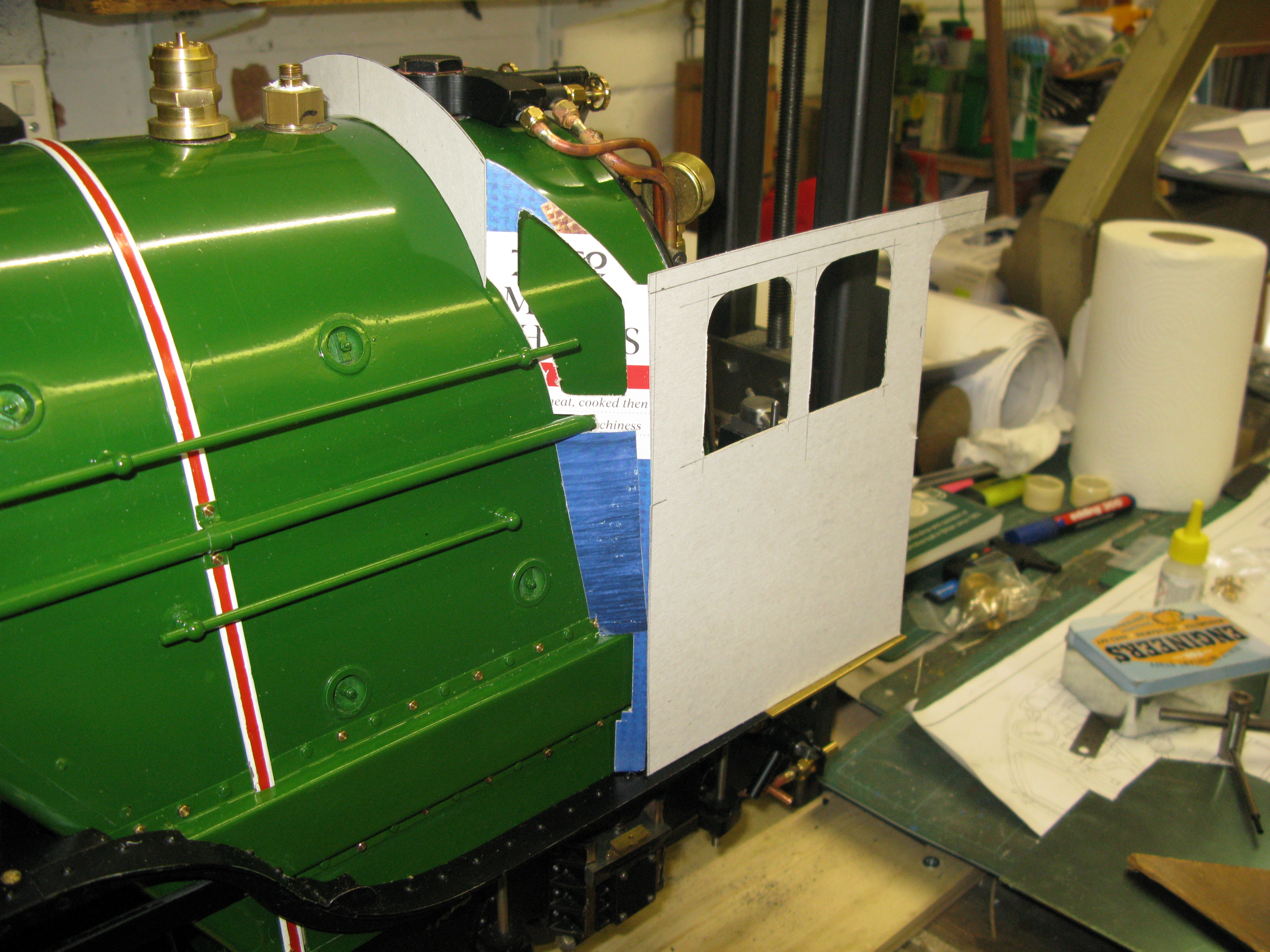
To make sure it was all “looking” right I chose to cut out the windows to get a perspective of the cab as it would look.
The next problem for the templates is, will the roof curvature match over the angled section? Also I have to make allowances for the tabs to join the parts together which will be done by 10BA c/s screws. The allowance for the roof tab can be seen on the cab side template. Although not plain in the above photo the cab side actually bends inwards towards the top at aline just below the window frames.
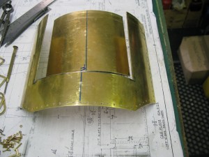
Time to cut brass. The cab is made from 18g brass, quite sturdy. The first brass to be cut was the spectical plate on tho of the boiler A relatively simple operation but the curvature had to match the cladding and fortunately marking out from the cardboard template produced a reasonably good fit with only some light filing here and there to get the fit.
Then followed the cab side. The window cut outs were done with an “Abra file” this is a slender rod type file that will fit in a hacksaw frame. This allows roughing out followed by filing to get the finished size.
The cab side has 1/4″ x 1/4″ brass angle soft soldered to the bottom which is used to fix to the cab floor by two 8 BA r/h screws tapped into the floor. The cab bottom was marked out on the running board to be the correct distance from the rear of the cab floor and from the edge of the running board. I then tried the cab side in place with the spectacle plate to see if the cardboard template for the angled window section fitted OK. It seemed to.
I then rolled the roof to the as drawn measurements but with a longer side to side measurement to allow for trimming. This showed that the cardboard angled window section did not meet up with the roof curvature, which is what I suspected might happen. So when I cut the brass for this section I left the height with a generous margin so I could subsequently trim it to fit.
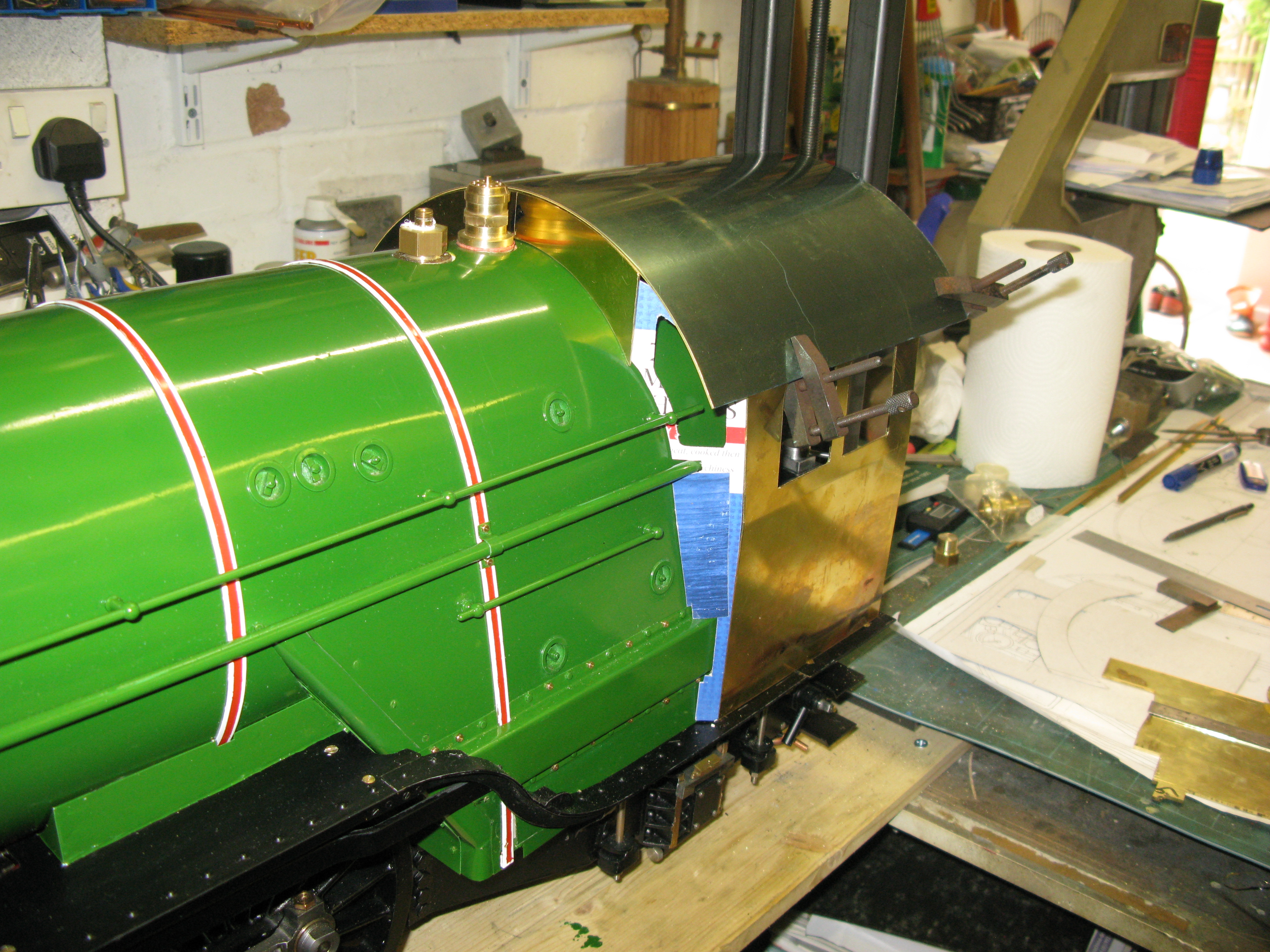
Checking the roof curvature to angled spectacle plate _ a small gap at the top
Having cut this section with its fixing tabs I found that it did not fit as the cardboard template did. The reason was the bend at the fixing tabs. The drawing shows nice angled tabs with a sharp angle. ……. not achievable with 18 g brass! even though I do have a home made brake press that can produce good bends on thinner sheet. So there was a lot of filing and test fitting to get this section to fit flush with the cladding and get the cab side vertical.
Having got a reasonable fit I then decided to bolt the cab side and window front section together to make the test fitting more representative by fixing the cab side to the cab floor each time a trial fit was made. Eventually I achieved a good fit and the also lined up with the spectical plate position which is 3/16″ behind the safety valve.
Now the fitting of the cab roof could be tackled by filing down the top of the angled window section. Again lots of trial fits, on and off to achieve a result except for the join right in the corner where the cab side joins which was light on material.
Having got a reasonable assembly of the three parts I chose to solder in place the 10 BA nuts for the fixing screws to make assembly easier.

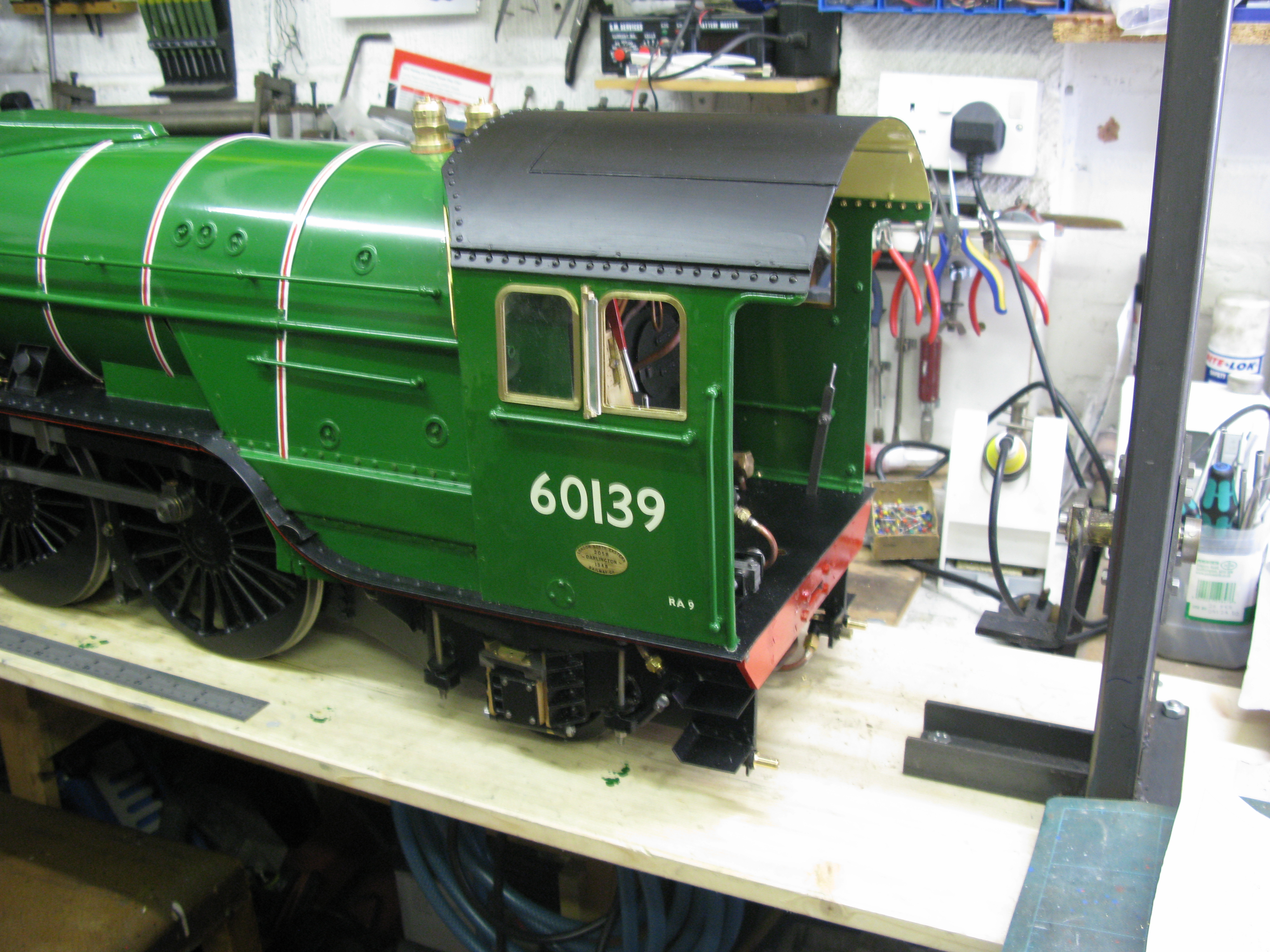
The finally fitted left hand cab structure
The hand rail had to be shortened a little to avoid fouling the window.
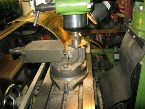
The windows in the cab sides have a frame to be fitted in the cut out. This gives a proud beading on the front 1/8″ wide. The frame is not drawn anywhere so its my own design. It consists of a T shape on its side so the top of the T is the beading. The tail of the T fits the cut out and also provides a rebate into which will be fitted the plastic window.

To make the frames they were designed in my CAD/CAM and cut on my little CNC mill as can be seen above. It takes about 2 3/4 hours to cut one frame.
A finished window frame

Another view showing the T type profile
There is a 3/16 half round bead along the back edge of the cab side and this has two nasty curves to accomodate. There is no way that the beading can be bent to form these small curves so my method was to turn a circular profile and then cut a 1/4 diameter out.

The photo above shows a completed cab side complete with hand rails. The profiled beading to fabricate the curves can be seen just above the cab side top.
In the middle of this cab work I find out from photos of a friends A1 that there is a false cab floor which raises the floor height. This promted me to look at Tornado, and yes it has the raised cab floor plus a further raised section at the drivers and fireman’s position. This then answers the question why the fire hole door looks so high.
Now my dilemma is what to do as I have the rocking grate and damper door levers all fixed to the cab floor at present.
Still pondering.
In the meantime, getting on with the wind deflectors that fit between the two side windows. They are hinged and have a 3/4 frame which is made from 1/8″ square brass with a 1 mm slot milled down the middle to accomodate 1mm thick acrylic glazing. The top and bottom of the frame are silver soldered to the main upright. The hinge mechanisms are fitted top and bottom and are in the form of a L bracket which is screwed to the cab side with a 12 BA screw from the inside. The main vertical frame has a 0.023 pin in the top and bottom held in place with loctite that match into holes in the L brackets.
The front spectacle plates have to have an angle strip along their top edges for the roof to fit onto. Rather than trying to bend ready made angle I am going to silver solder a strip at right angles to the plates.

Front spectacle plate window frame

A side panel with makers plate, wind deflector and dummy wash out cover
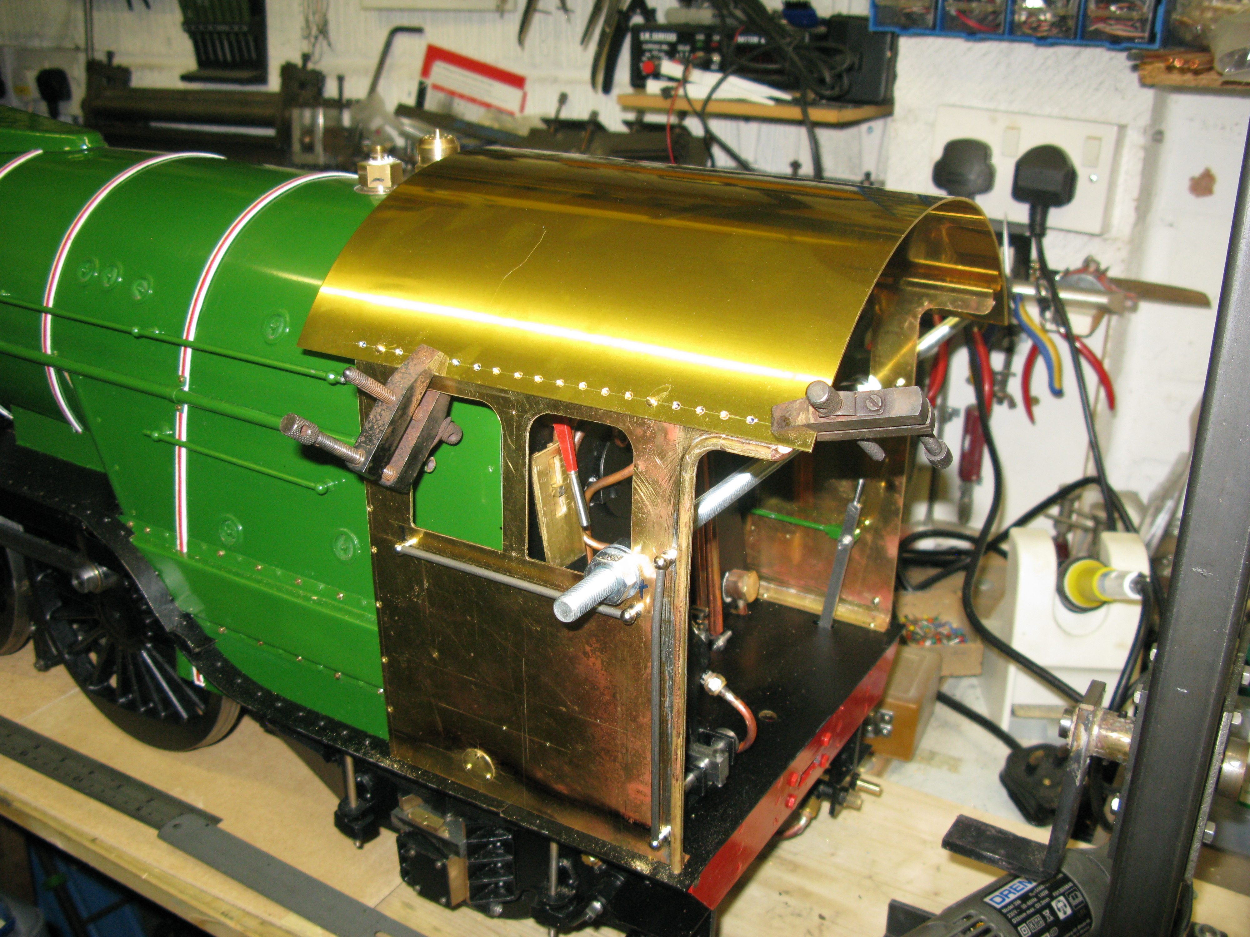
The commencment of cab roof fitting
The cab roof fitting I am finding not too easy. In the photo above I have a temporary stiffening rod between the side panels to hold them rigid and upright. One side has had holes drilled in the roof for no slot 8BA screws to simulate rivets This will enable the cab to be removed by removing the roof. The far side has to be cut to length and the angles cut for the front window spectacle plates.
The far side is now cut to length and the fixing holes drilled for the no slot 8 BA screws. Also the cab back has been trimmed to length and the corners cut off above the front window spectacle plate.
The next job is fitting the strip to the front spectacle plates to form the angle to which the roof bolts. The flat front strip in the middle was straight forward as it just consists of a straight strip 5/16″ wide bent to match the roof curvature and silver soldered in place. The strips above the window spectacle plates were a different matter as they are a compound curve to follow the roof curvature at an angle. A peculiarity of compound curves is that aligning the strip to the straight face of the spectacle plate requires a curved shape on the strip edge.
To ensure the strip was silver soldered at the right angle to the spectacle plate and the roof I decided to spot solder the strip in place with the spectacle plate and roof assembled complete with side frames and front spectacle plate to ensure everything was square as it should be. To stop the silver solder running through the gap and joining to the roof I coated the roof with Tipex fluid ( a typing correction fluid) under the join. This prevents the silver solder bonding to the roof. A single clamp was used to hold it in position. Once the tack was done the spectacle plates were disassembled and the strip fully silver soldered in place.
Having successfully soldered the strips the whole cab structure was reassembled and the fixing holes drilled for the fixings. The fixings roof to window spectacle plates are 8 BA no slot screws but the fixing of the front spectacle plate is by permanent r/h rivets as this can come off with the roof whereas the window spectacle plates have to move outward away from the cladding to clear the obstructions. This means the side cab frame and window spectacle plate can be permantly fixed together on final assembly.
Attention is now turned to the removeable section of the roof that allows access to the various things needed to drive the loco. The cut out is 6″ wide by 6 3/8″ long. The cut out will eventually be used as the removeable roof part by giving it sliding runners.
To cut out the curved roof sheet and to get a nice straight clean cut so the cut out part would fit back in again I used a slitting saw on the mill. Initially I started with a 1/64″ saw of 4″ diameter, but that soon started to stray off line due to it bending even with the slowest of feeds. So I changed to a 1/32″ x 3″ saw and performed OK.
Whist machine minding the above cutting process with its very slow feed I had a eureka moment re the cab floor problem. All I had to do was to make a removeable false floor section that gave access to the tender drawbar pin and the grate rocking levers as access is not needed when driving. The only bit needing access when driving is the ash pan door lever when the doors are being used as dampers. Guessing, there may well be plenty of air to feed the fire with the doors shut anyway as there are air holes in the front of the ashpan and a large slot at the rear.
Having cut out the removeable driving section the method of making it slide in and out was chosen to be a rebated bar soldered to the underside of the roof forming a slot with the roof sheet into which a plate soldered to the underside of the sliding portion would fit. The as drawn solution was just a simple put in place removeable part so the removeable bit overlaped the cut out. Its a bit more work to do what I have chosen but gives a better roof line and uses the cut out material.
On full size there are roof ventialtion slides on both driver and fireman sides but I am not putting those in. There is also a plate to access the fountain on the boiler but that will be omitted too. I am not into super scale detail.
Painting and window fitting underway – sorry for poor picture
The window glazing is 1mm acrylic a press fit into the frame. The frames are a press fit into the the structure wih just a dab of super glue in two or three spots to give retaining medium.

Two cab sides completed.
On the iside there is a frame the same size as the outer but not with rebates and this is epoxy glued in place making the whole assembly secure.
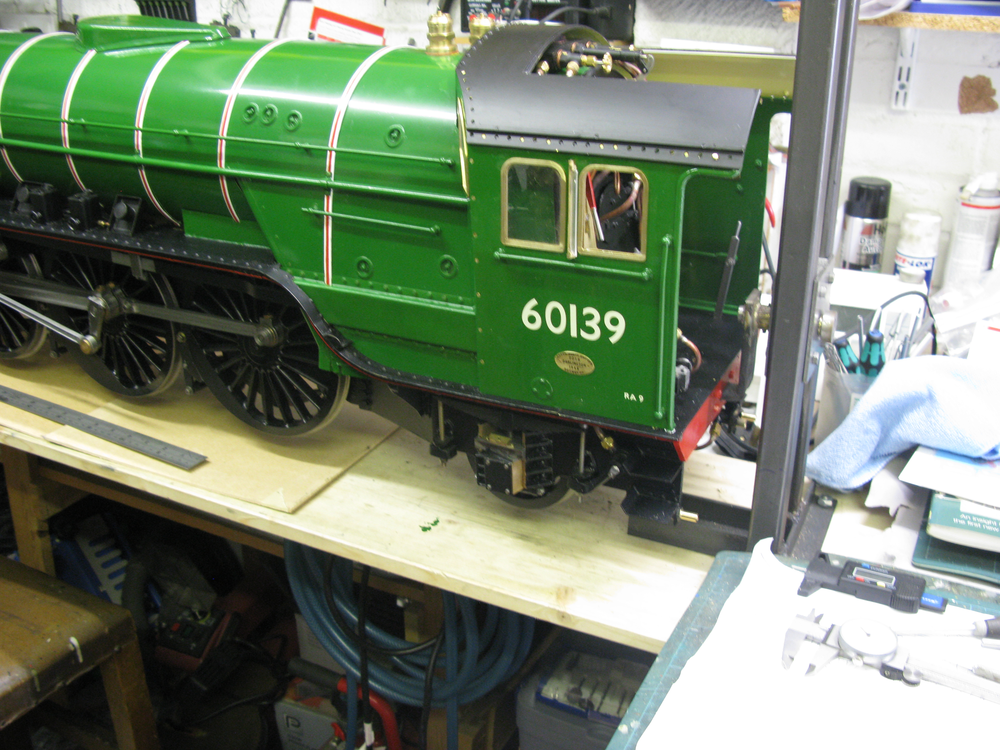
An assembled cab
With all the painting done the cab is now assembled. In the picture above there are dummy rivets to go along the cab roof line. These are no slot round head 8 BA screws, however as bought they are too large to match the real rivets in the front spectacle plate so they are having to have the heads reduced to match, only 40 to do!

View from the front – unfortunately the depth of field makes the cab fuzzy.
Fitting the dummy rivets is proving diificult especially towards the front of the cab. Where the cab cut out is located I can get the nut to screw on by hand but towards the front of the cab my fingers do not fit so the nut has to be held in position with a scissor grip and the rivet turned into it, which is the difficult bit due to its small size. For the ones at the very front I have resorted to gluing the rivet head to a cocktail stick which gives just about enough purchase on the head to turn it into the nut. Once started I can get a long spanner on to tighten it up and remove the cocktail stick. Having done most I tried using a pin vice to hold the head and this worked better than the cocktail stick but it was still tricky to get the had held square in the pin vice so it could be turned without too much wobble as other wise engaging the nut was too difficult.
Cab roof all fixed down and complete.
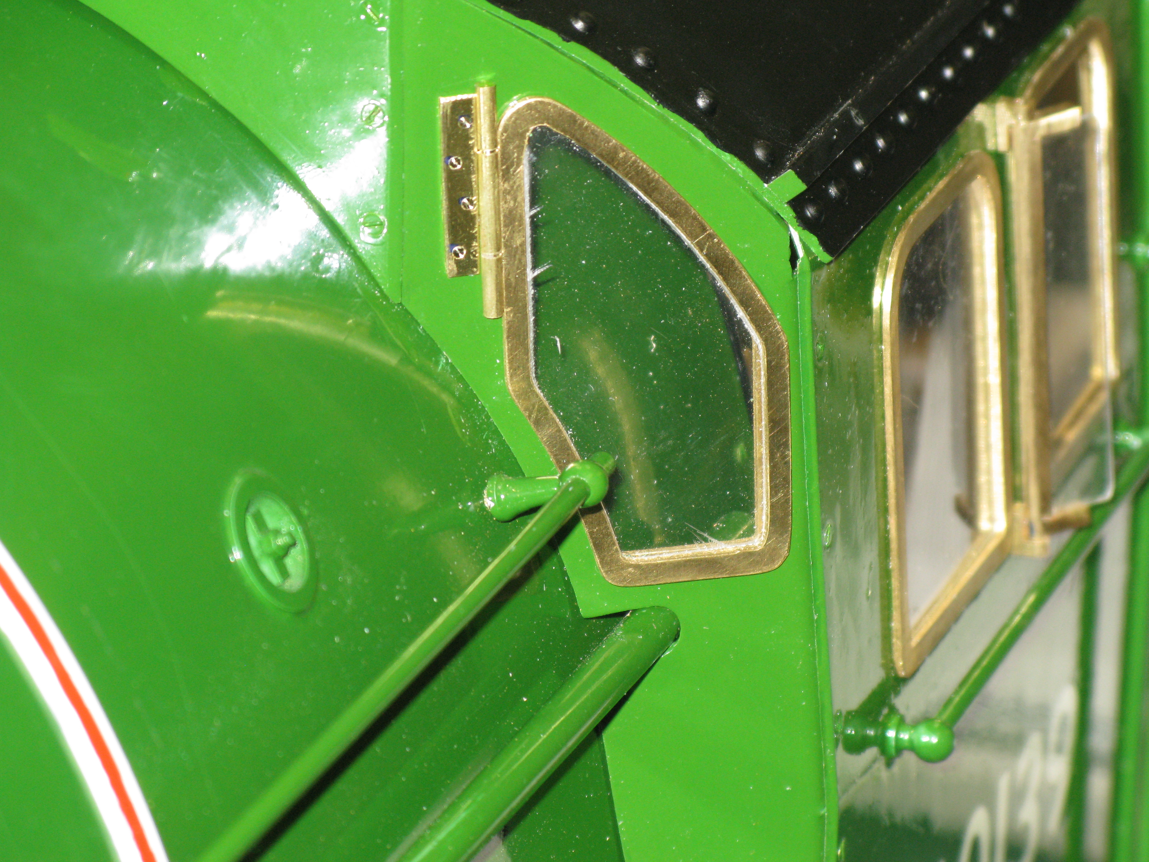
Dummy hinge glued in place for the window.
With the cab essential complete I can now turn to the false floor.
I first tried a cardboard section to see how it would go around the reversing pedestal etc.

This was actually 1/8 too high judging from photos of the Tornado cab. Also the tapered section does not go down to the existing floor. There will also have to be something that looks a bit like the cardboard template sitting on top with the tapered section. So to start I decided to make a piece 1″ high that goes from cab sided to cab side and fits flush to existing floor edge held in place by the hand rail lower staunchion fixing. The piece having 14/” x 1/4″ angle soft soldered to the top to allow the false floor to be fixed to it.

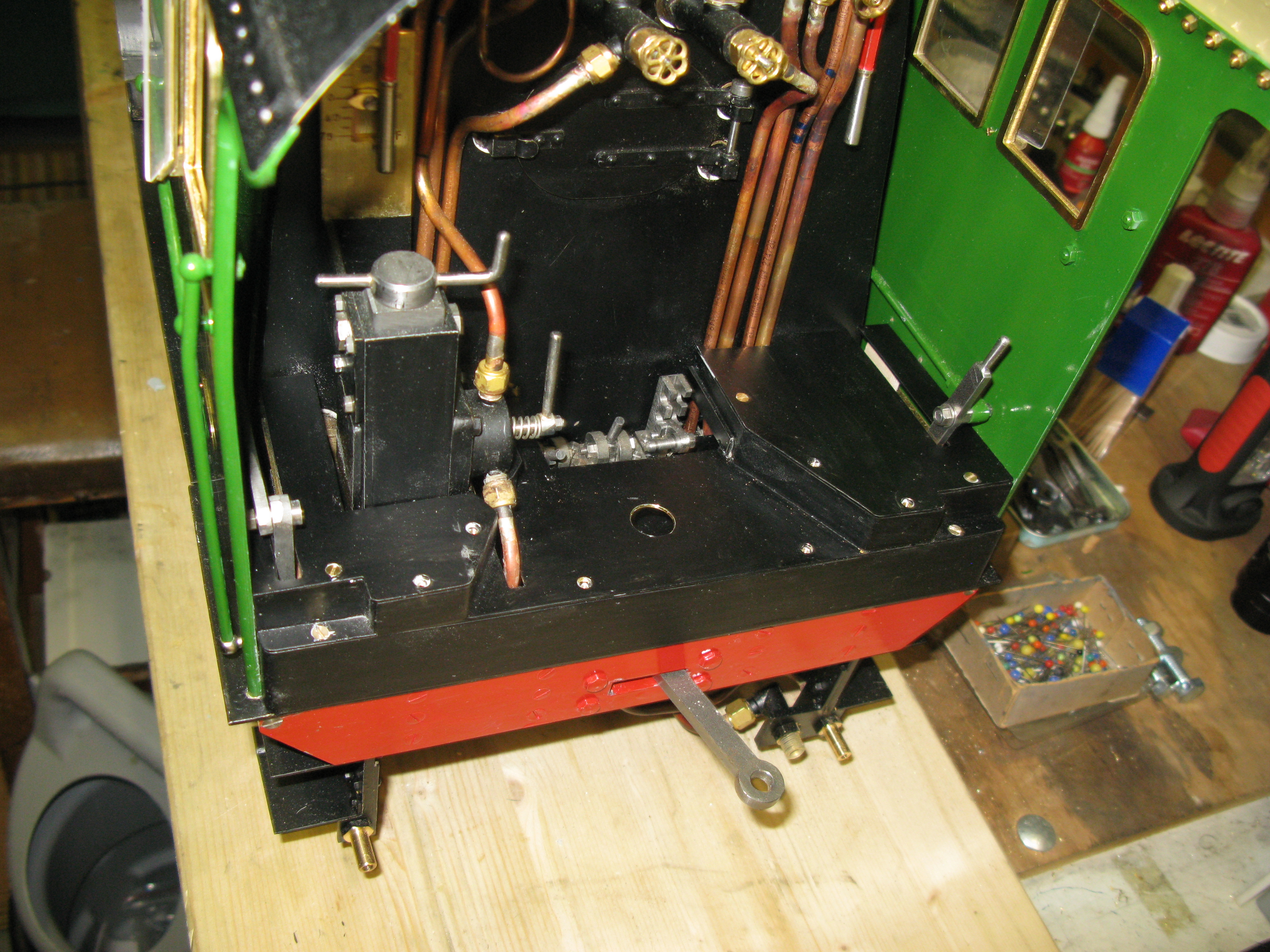
The false floor
The false floor had numerous slots to clear various bits. The most difficult being around the reversing stand and brake valve which is going to be in the way again when the next floor level is put in.

The driver and fireman’s raised portions are now fitted. Unseen is a piece between the brake valve and front cladding as well. The gap in the centre allows access to the rocking grate levers and the ash pan door lever. This gap will have a cover over it which will simply rest in place to give easy access at the end of a run.
All the top surfaces will now be wood planked.
I did toy with the idea of putting in the driver and firemans seats and back plates but at the moment I am unsure if they will interfer with access for driving. The jury is still out on that. One problem if I do is that the fireman’s side has the drain cock lever in the way as it is set back too far in the cab (as drawn) another 1/2″ or so forward would have been better.
In case in need to put the loco on the turnover frame again I will have to remove the tender coupling bar. With the
false floor in place this is not possible so I have drilled a hole above the coupling bar pin so it can be extracted. This hole is covered by the wood floor.
The wood floor parts use two of the false floor fixing screws to hold them in place.

The floor in front of the fire door is removeable by just lifting out to gain access to the rocking grate levers and ash pan door lever.
The floor is beech strips glued together and varnished. I may put a steel sheet protector on the fire hole door step but not covering the whole area.
Having put the floor in place I have decided against trying to emulate full size with the driver and fireman’s seats and back protections which means that there will be no cab doors either as theses are mounted to the seat back sheets.
There is a fall plate to go between cab and tender but I cannot do anything about that until I have the tender built and coupled to the loco so I can get the dimensions right. There is no drawing for this.
