This chapter will cover all the outside motion, i.e. the moving bits.
Pistons
The first job is the pistons. These are made the same way as I made the inside cylinder pistons so I will not repeat what I said there but just publish a few photo’s of the progress in making them.
First of two pistons made. No rings yet.
Just as a reminder. The pistons are of the split type so the rings can be fitted without expanding them over the OD.
Second piston – first part sealed on with loctite and outer diameter rough turned, inner diameter turned to size.

Second piece being rough turned, bored and threaded.
Second piece mounted on the piston rod.

Second piece inner diameter turned to size and outer diameter turned to roughly match the first piece.

Final piece added having been rough turned and parted off in the 3-jaw chuck and then the overall diameter turned down to fit the cylinder bore.
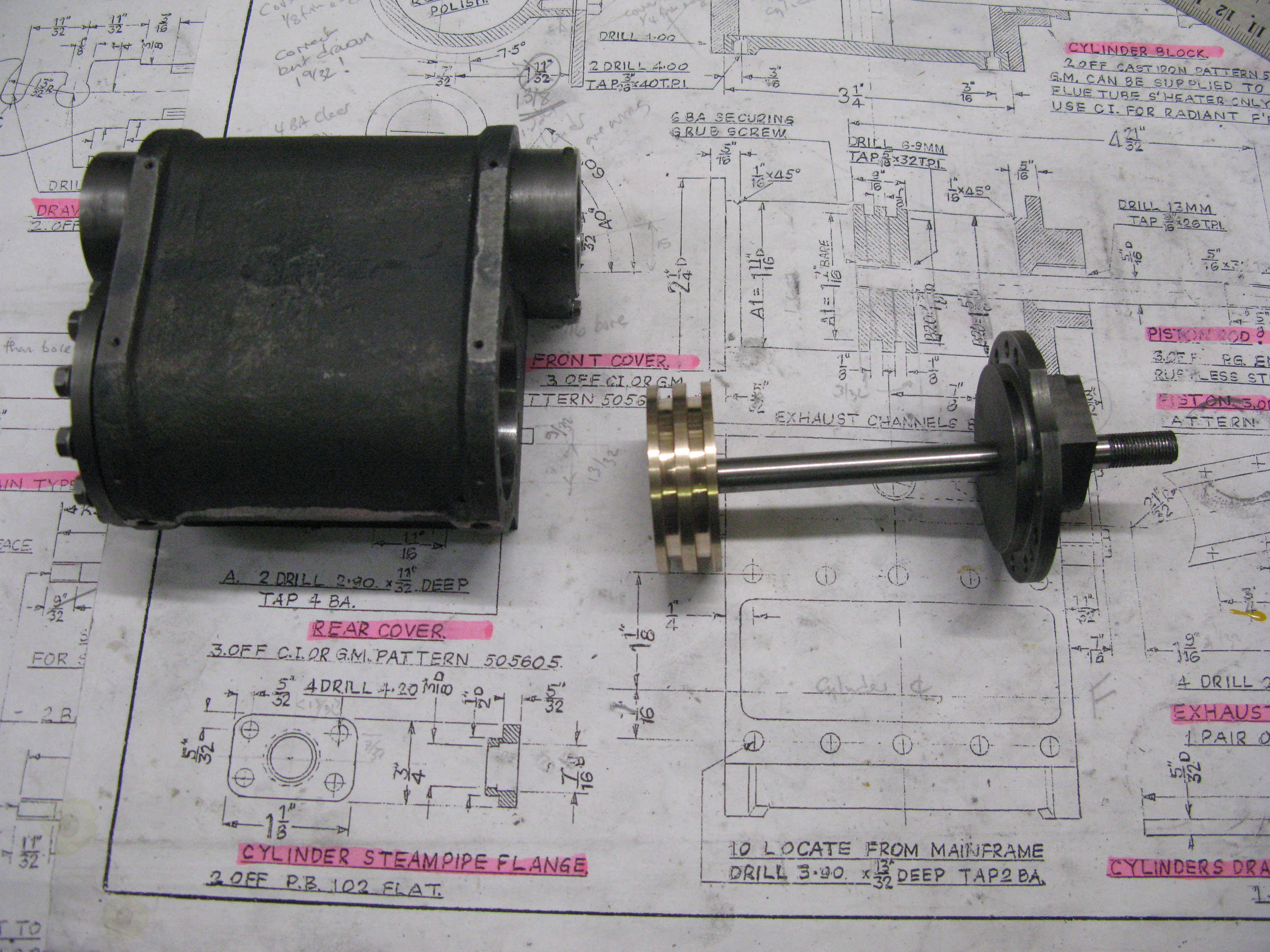
Second piston completed and fitted successfully to the bore and back cover plate.
The piston rings are cast iron and 1/8″ square in section so a big lump of cast iron is turned into swarf to produce them. Basically a turning and boring job (no pun intended).
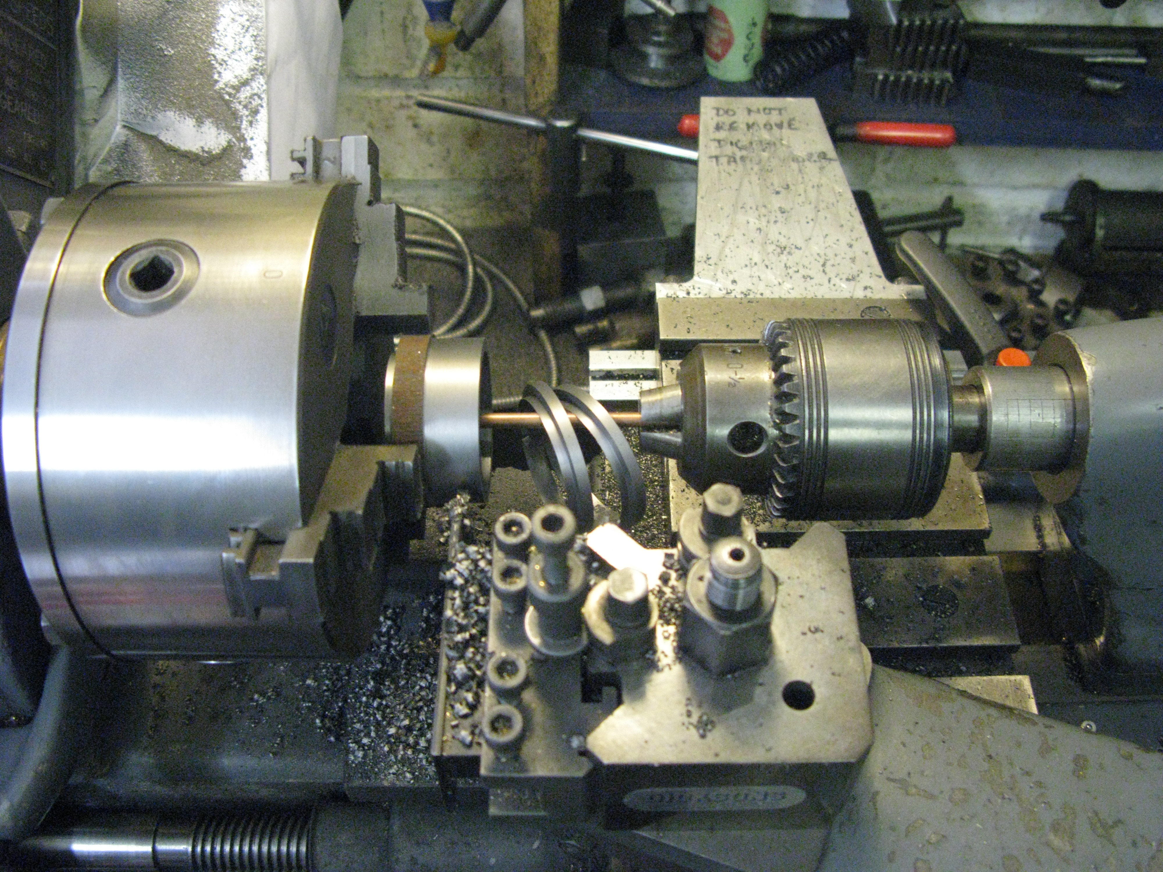
Four piston rings in manufacture
The rings were cut using a Dremmel cut off wheel and then the four rings expanded onto a 3/32″ spacer and heat treated at 800 degrees for 15 minutes. It should have been 600 degrees (as the middle cylinder was done) but I lost the plot for some reason! Anyway when they had cooled naturally there was surface oxydation that had to be cleaned up with emery cloth.
The rings were fitted to the piston OK.

First ring located.

All rings fitted
Once all the rings were fitted the piston was inserted into the cylinder. This is no easy task as the rings are quite stiff. I put a very small chamfer on the cylinder block bore to assist getting the rings into the bore but it was still a struggle. Once in the piston moved along the bore OK. The rear cover was put on to hold the piston rod central and the piston worked up and down and whilst smooth it was fairly stiff due to the wall pressure of the rings. Once satisfied that the pistons were OK in their bores they were taken out and a locking 6 BA grub screw put into the end to fix the entire piston assembly in place.
6BA grub screw fitted to lock the piston assembly in place
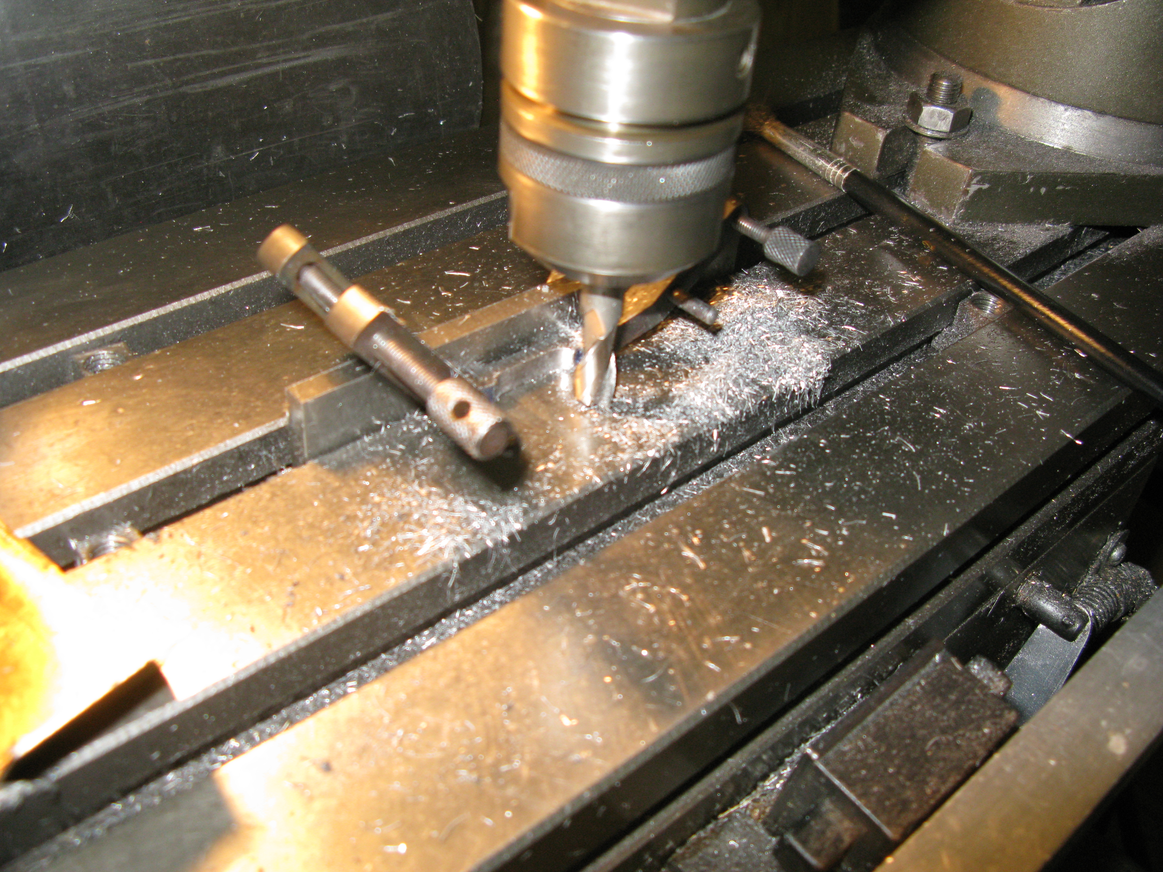
Valve bobbins
The valve bobbins fit onto a 7/32″ dia valve rod. The valve rod has one end reduced down to 3/16″ with a flat that slides into the front valve cover. The rod is a straight forward turning task with a 7/32 x 40 ME thread 1/4″ long on each of the ends of the 7/32″ dia. section.
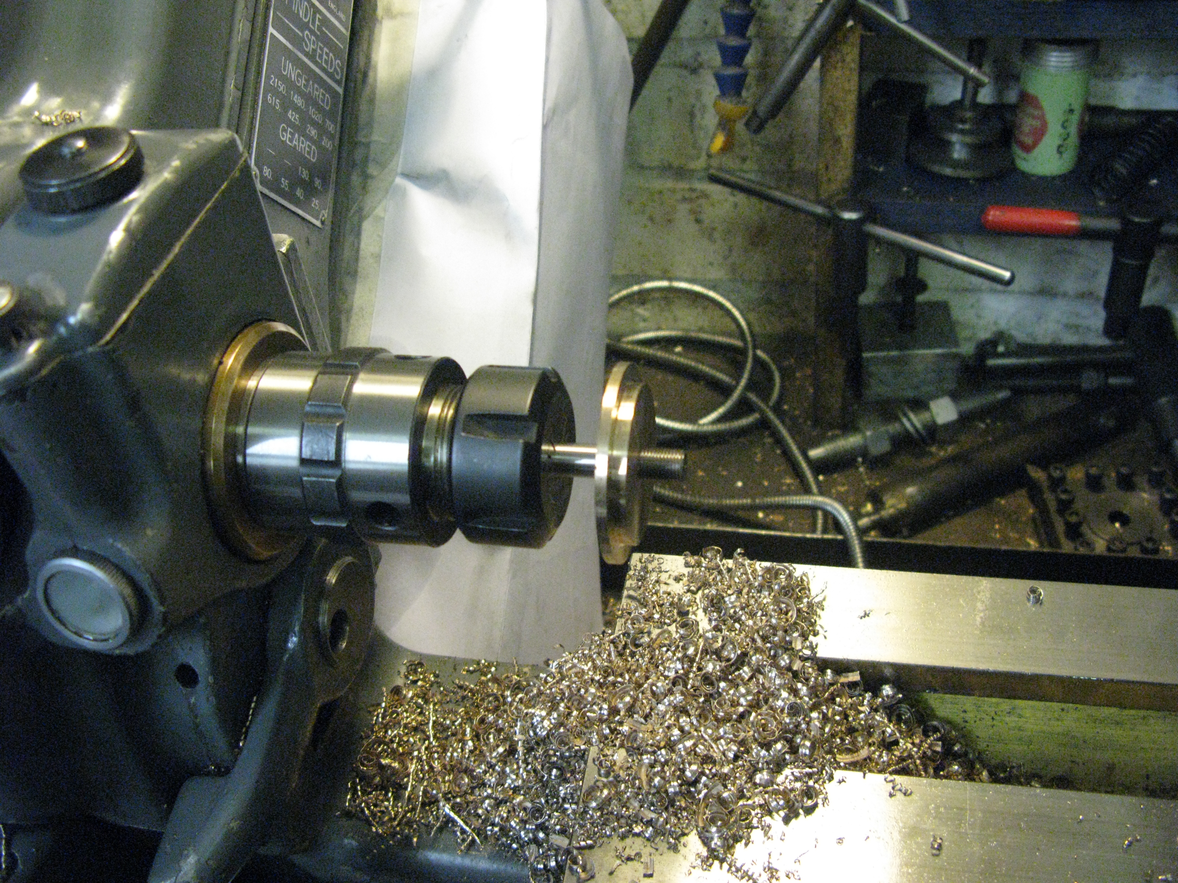
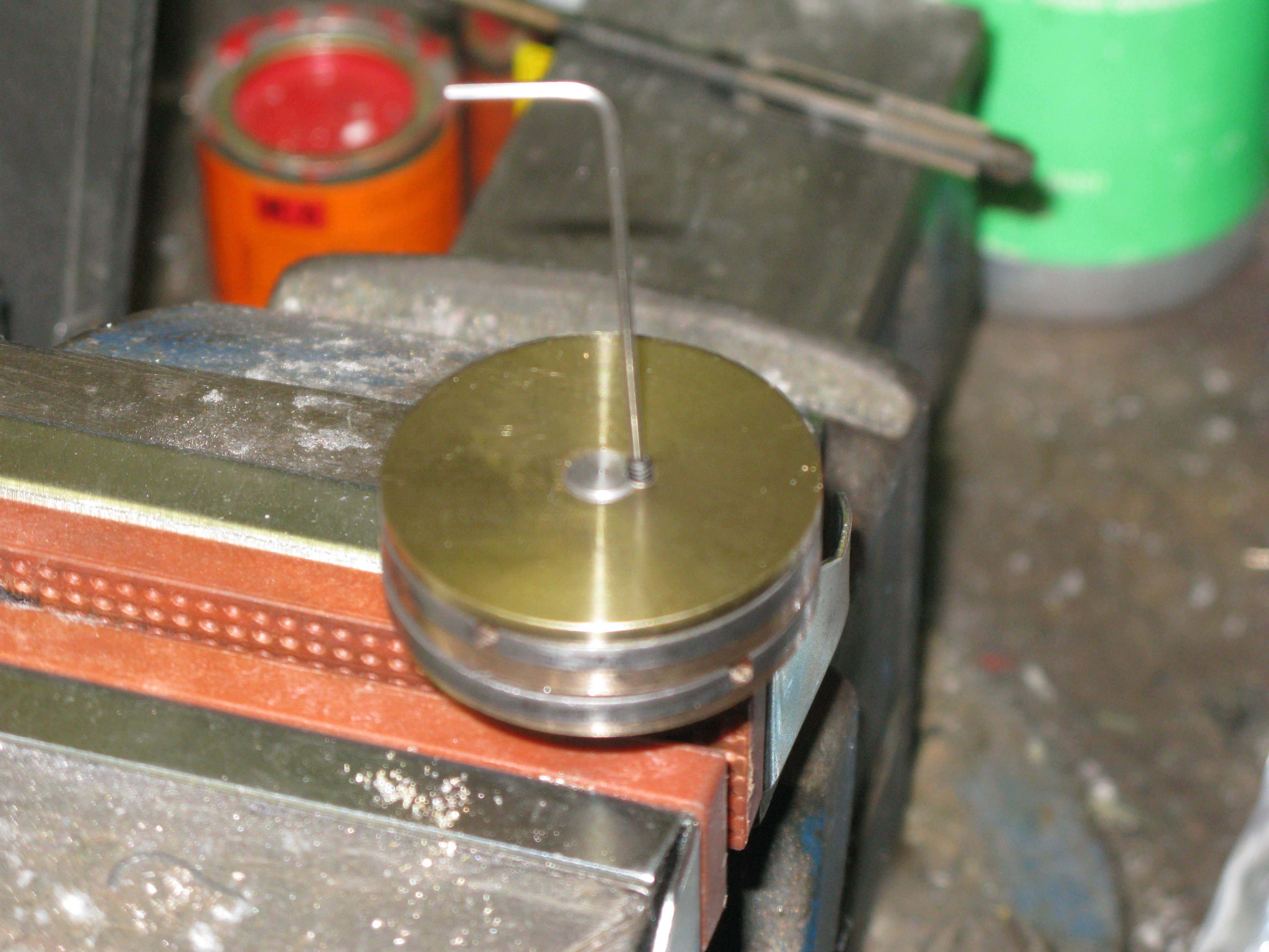
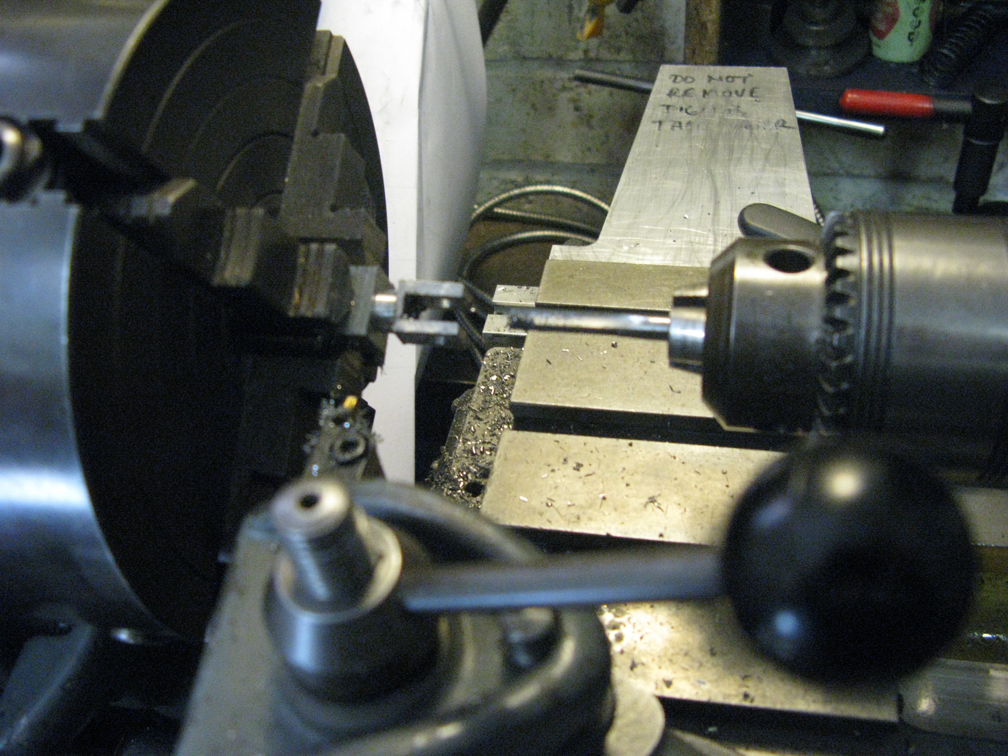
The bobbin needs a 7/32″ hole through it and this is drilled first in the lathe. It is unlikely that no matter how carefull the drilling exercise is undertaken the likelyhood of the drill emerging dead on centre at the other end of the work is slim. I put a 3/16″ drill part way in first, as far as the drill length would allow and then followed by a long series 7/32″ drill all the way through. It was’n’t far out but had the bobbin be turned to diameter first the rod would not have fitted the guide or cover. (see the inside motion for the problem I had resulting in a new bobbin having to be made).
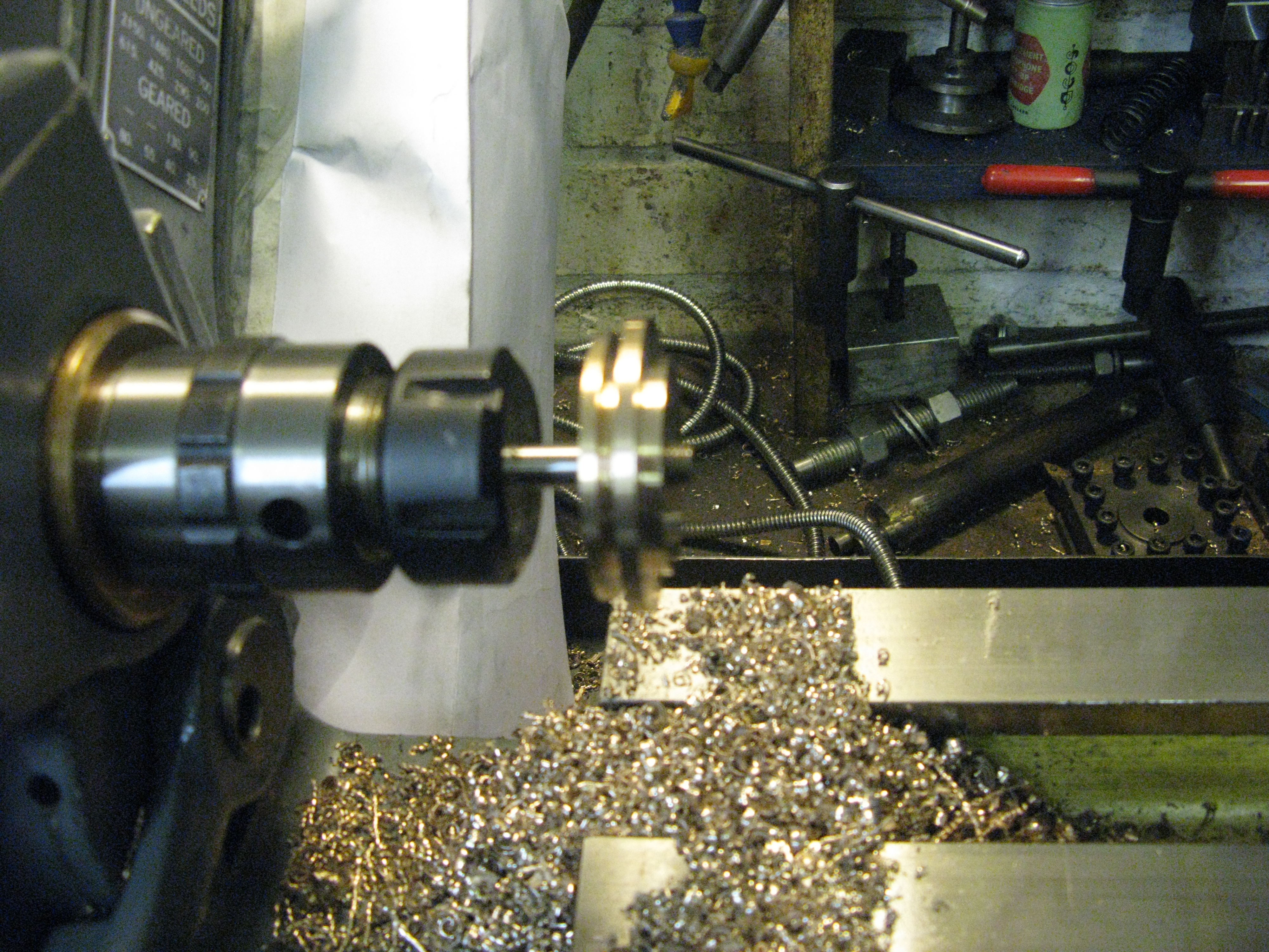
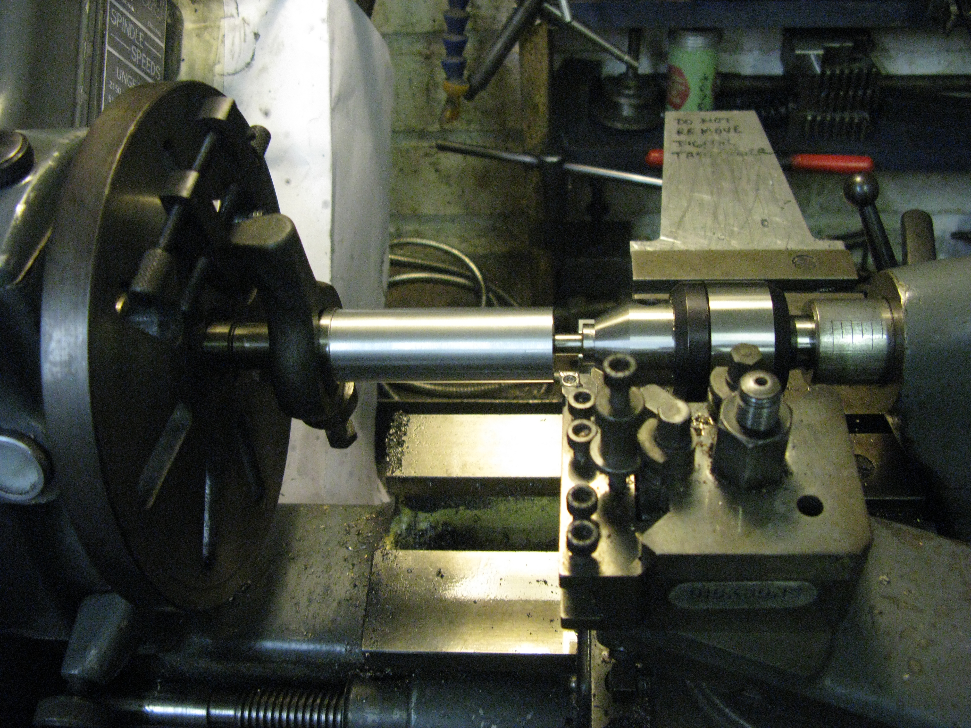
The bobbin was now set up between centres to turn the diameter and relief.
As with the main piston the bobbin employed split ends for fitting the rings.

The finished bobbin less rings – both made.
The piston rings were made with the same process as the main piston. The rings were simply cracked in the vice to produce the gap. This time I remembered to set the correct temperature for setting the gap and I coated the rings with “Tipex” (correction fluid) as it prevents scaling, for good measure. Give or take a thou, the clearances for the rings on the bobbin were 3 to 4 thou on the width and a couple of thou on the inside diameter.

With the rings heat treated they were cleaned up with fine emery paper and the gap abutting edges given a clean up with a swiss file. They were fitted onto their bobbins and the assemblies (well oiled) slid into place in the cylinder blocks. Fortunately the taper put onto the valve liners was sufficient to guide the bobbin into the the liner at the opposit end to the bobbin entry.
Cross heads
The cross heads were machined slightly differently than when done for the inside motion purely because of the material to hand. This was an 1 1/4″ square bar that I cut the end off 1/2″ wide and then cut that in half to make two cross heads.
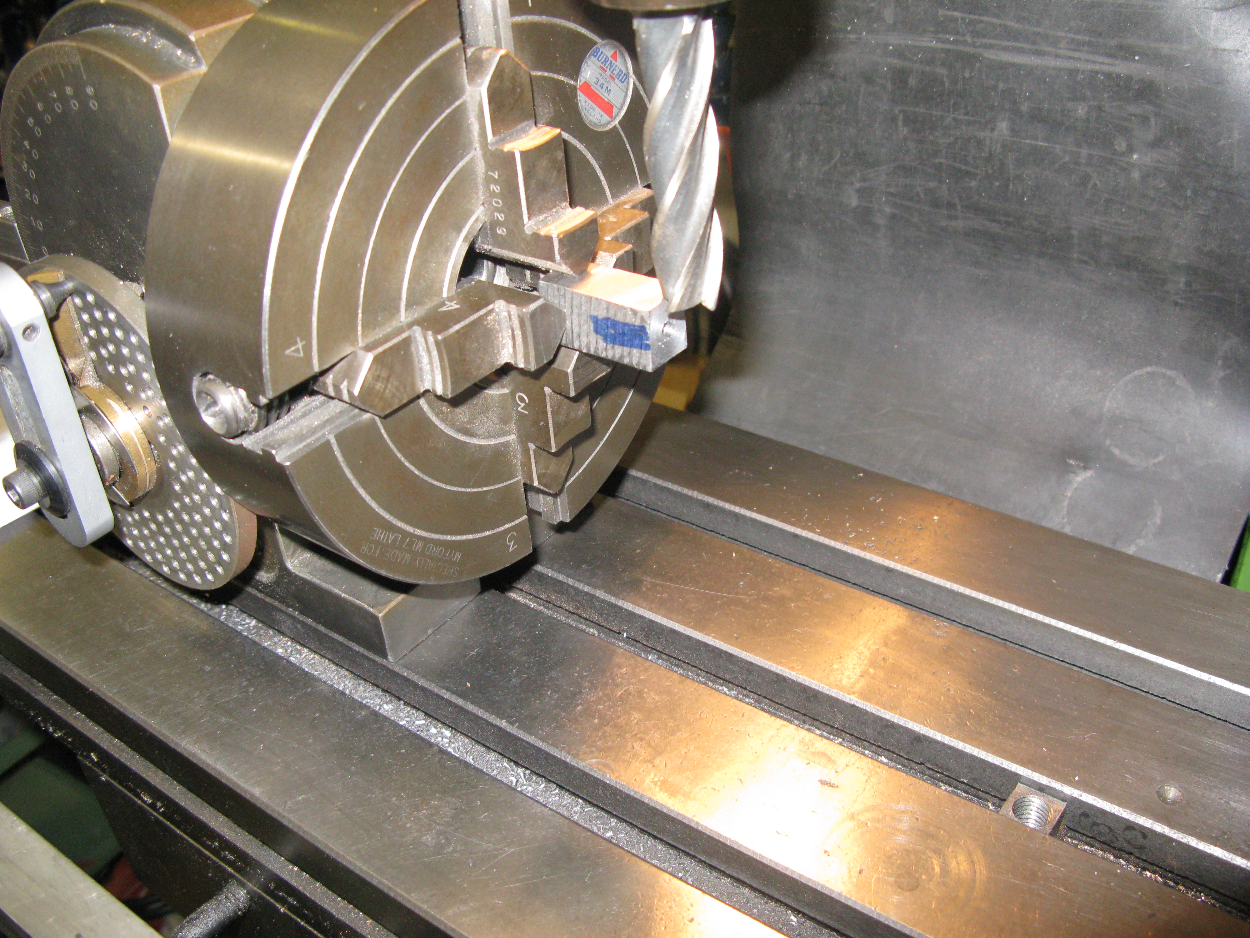
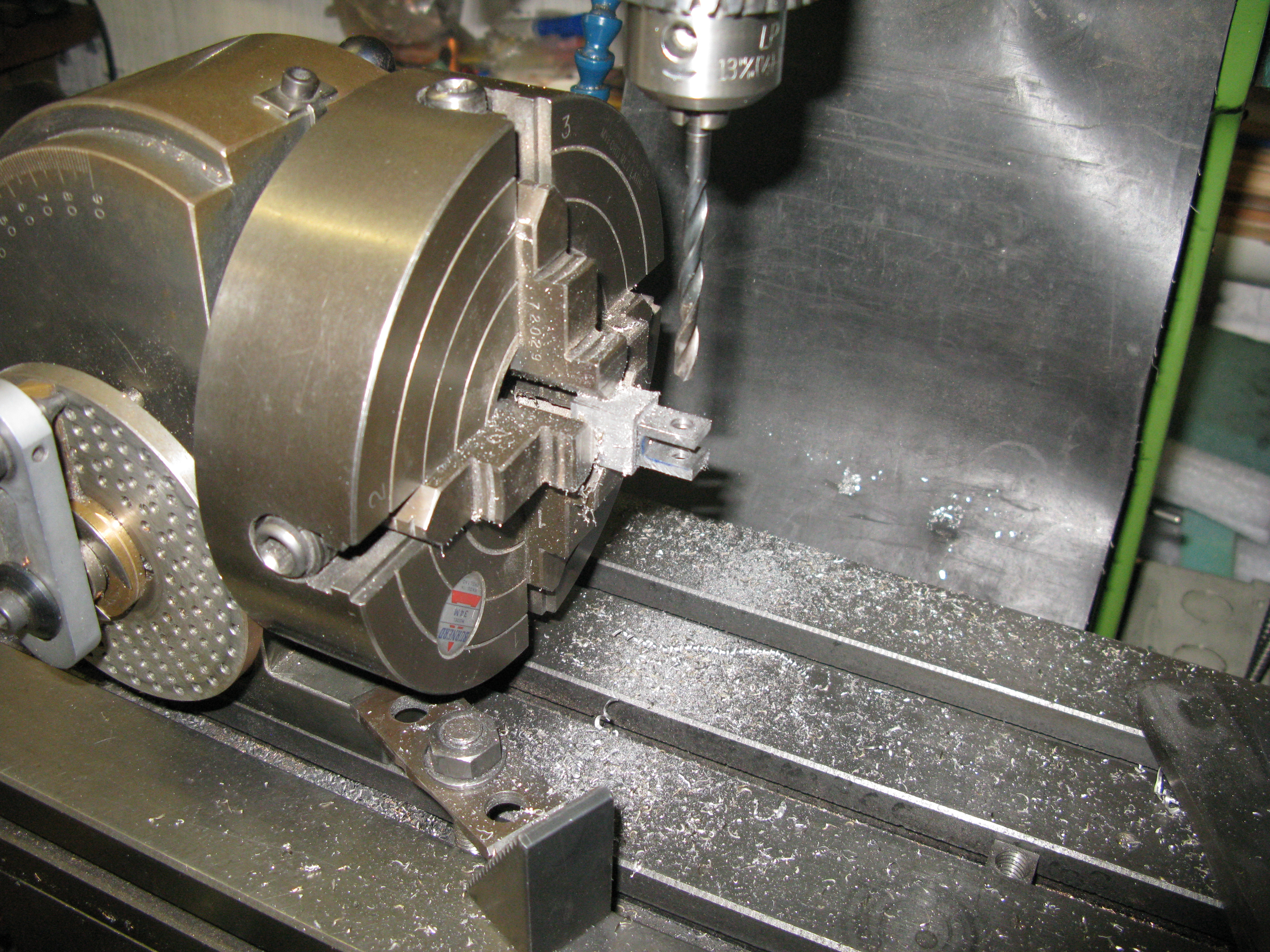
The first machining was in the four-jaw chuck on the lathe to true up the end and drill the hole that would eventually be tapped 7/32 x 40 ME. The chuck was than transferred to the dividing head on the mill to machine the rectangular profile.
The cross head is offset in the vertical plane having the hole centre 3/16″ below the top and 7/32″ above the bottom

Having machined the profile it was checked to ensure it would slide into the valve rod guide.
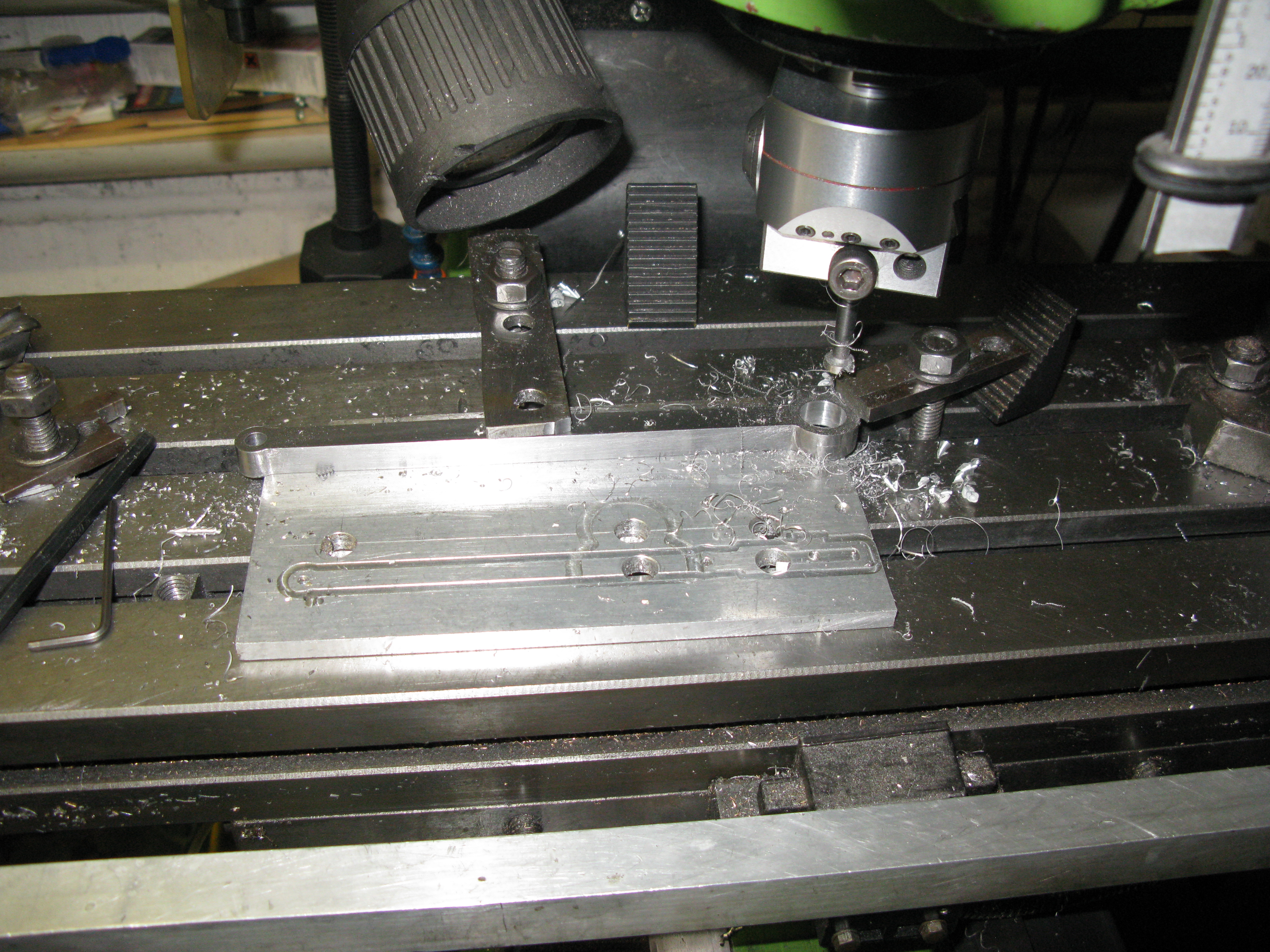
The slot for the combination lever was the cut in with a 7/64″ slitting saw with two cuts to give a 7/32 wide slot.

Next the the 7/32″ hole was drilled and reamed for the pin.
Back on the lathe the hole was tapped 7/32″ x 40 ME. and the boss turned down to 3/8″ diamter and 1/8″ wide and parted off.
The cross head was checked to fit the guide and that the valve rod would screw into the cross head and that assembled the piston freely moved over it travel (albeit stiffish from the newness of the bobbin in the bore).
Satisfied all was well the valve rod guide was assembled onto the cylinder block with high temperature loctite and set square and the four grub screws holding it in place tightened.

Setting the valve guide square
Slide bars
The slide bars are the same as the inside motion. Made from gauge plate 3/16″ thick for the top bar and 3/16″ square for thetwo bottom bars.

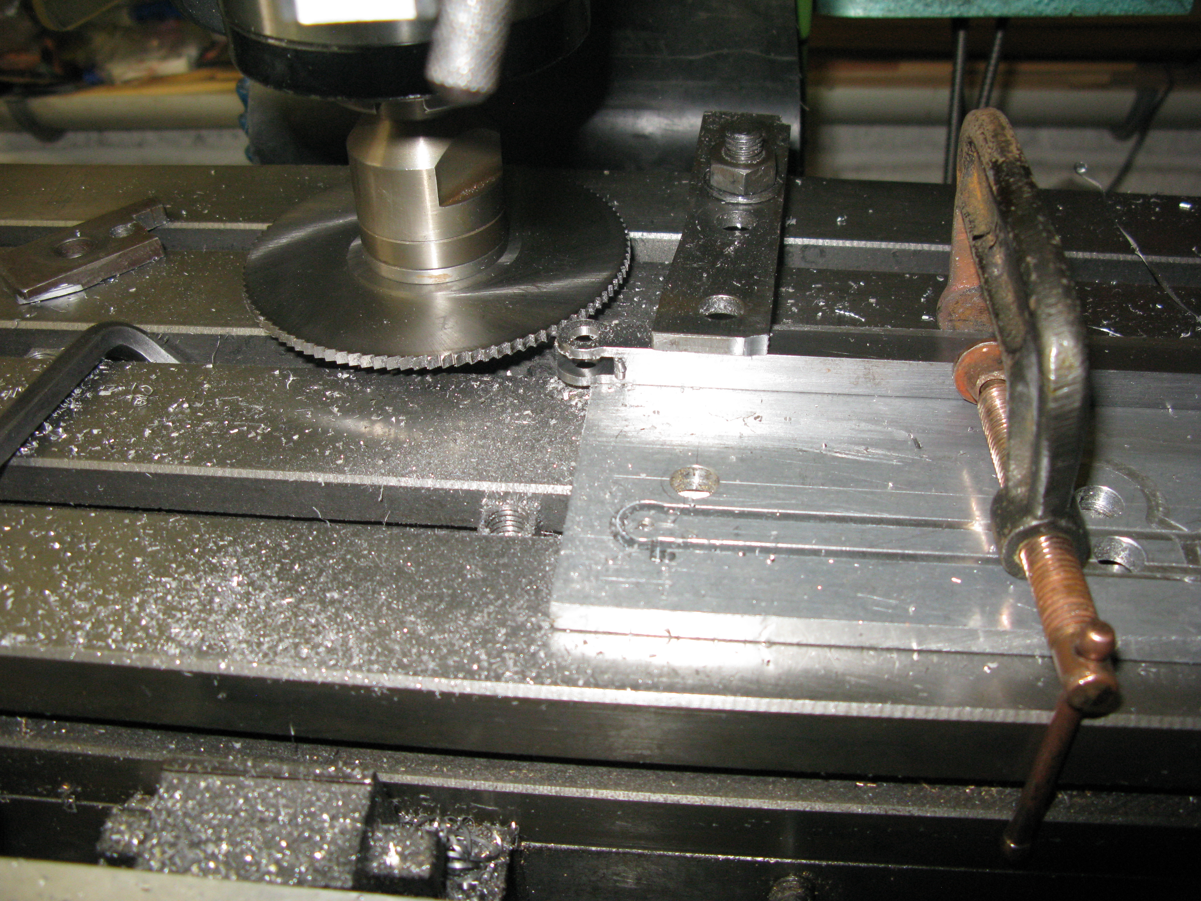
Slitting the gauge plate for the top slide bar
The slide bar top was drilled for its fixings to the cylinder cover and for the fixings of the two 1/8″ square underside bars. The fixing holes to the support bracket were not done at this stage as they have to be measured “on the job”.

The 1/8″ square bars forming the underside of the slide bar were also drilled and tapped 7 BA.

The cylinder cover was drilled for the slide bar fixing by centering it under the quill using a temporary bar to fit in the piston rod gland and ensuring it was horizontal by a drill fitted in a cover fixing hole alternately either side and measuring its vertical distance and adjusting until both measurements were equal.

Aligning the cover for drilling

The slide bar is then fixed to the cover and slid back onto the piston rod. With the cover nipped in place the position of the fixing holes for the support bracket along the length of the slid bar can be established and marked.
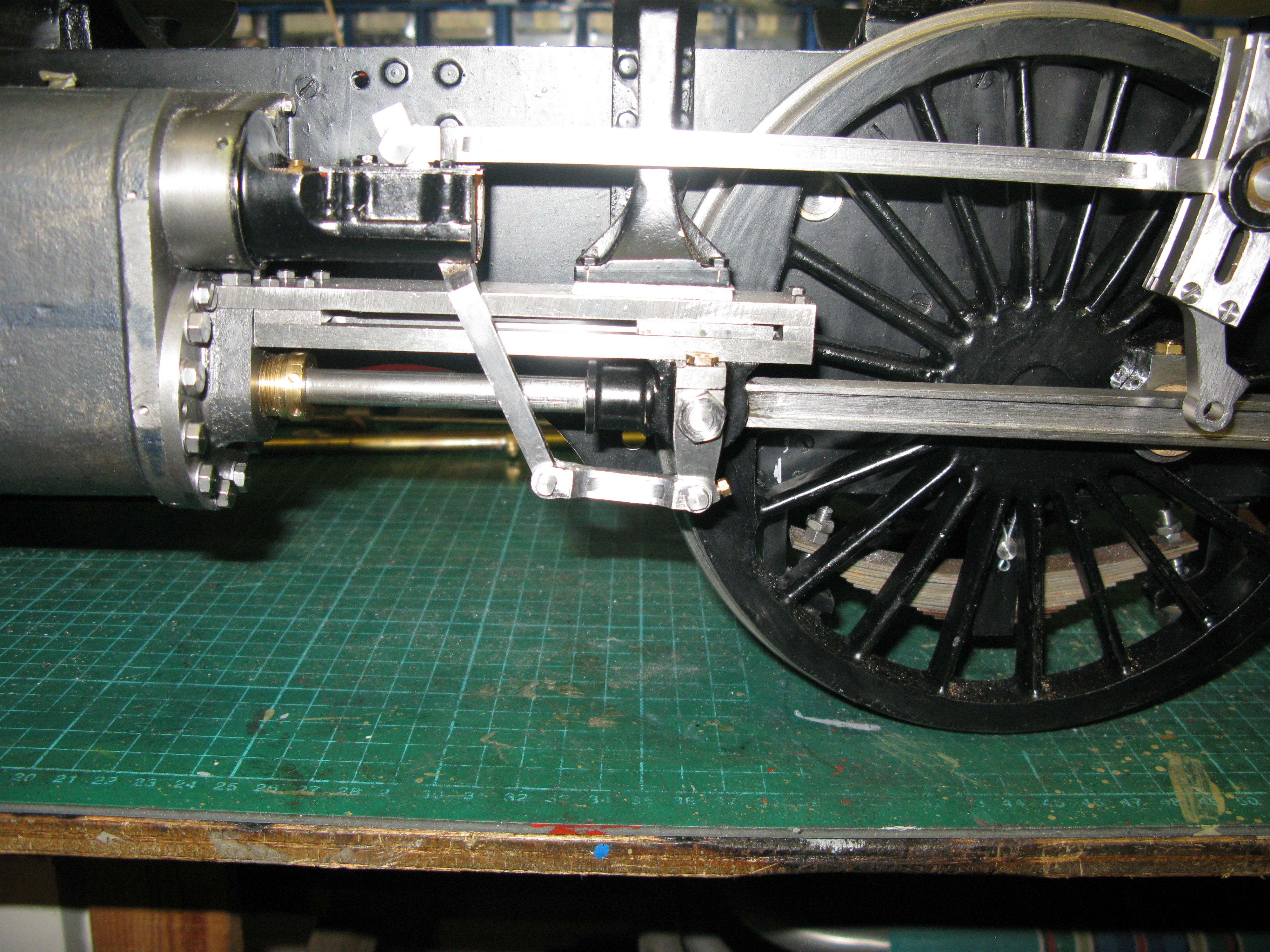
Also at this time a check can be made on the vertical height of the slide bar from the piston rod at the extremities of the piston rod travel. I found that the support bracket was too high and a gap was present. The cylinder cover was not too low as apart from it being machined to size there is insufficient room between the top of the slide bar and underside of the valve guide for it to be any higher. There is barely enough room for the fixing bolt heads. I reasoned that although the support bracket was made to as drawn dimensions that these were in error. It will be interesting to find out what gap exists on the other side when I get around to doing the second one. ( I suppose another possibility is that the cylinder is too low on the frames, but I rule that out as the fixing bolts for the cylinder to frame would be covered by the inside cylinder if the outside cylinder were higher).

Checking the gap between slide bar and piston rod with slip and feelers
The photo above also illustrates the dilema of how to fit the cross head without taking off the front cylinder cover and turning the piston from that end. There is just enough gap I think between the slide bar support and the valve guide to screw the cross head onto the piston rod and then move the cylinder cover up to it so the slide bar can be bolted to the cylinder cover and then slide it back to the cylinder block. Of course the slide bar support bracket can always be removed. We shall see.
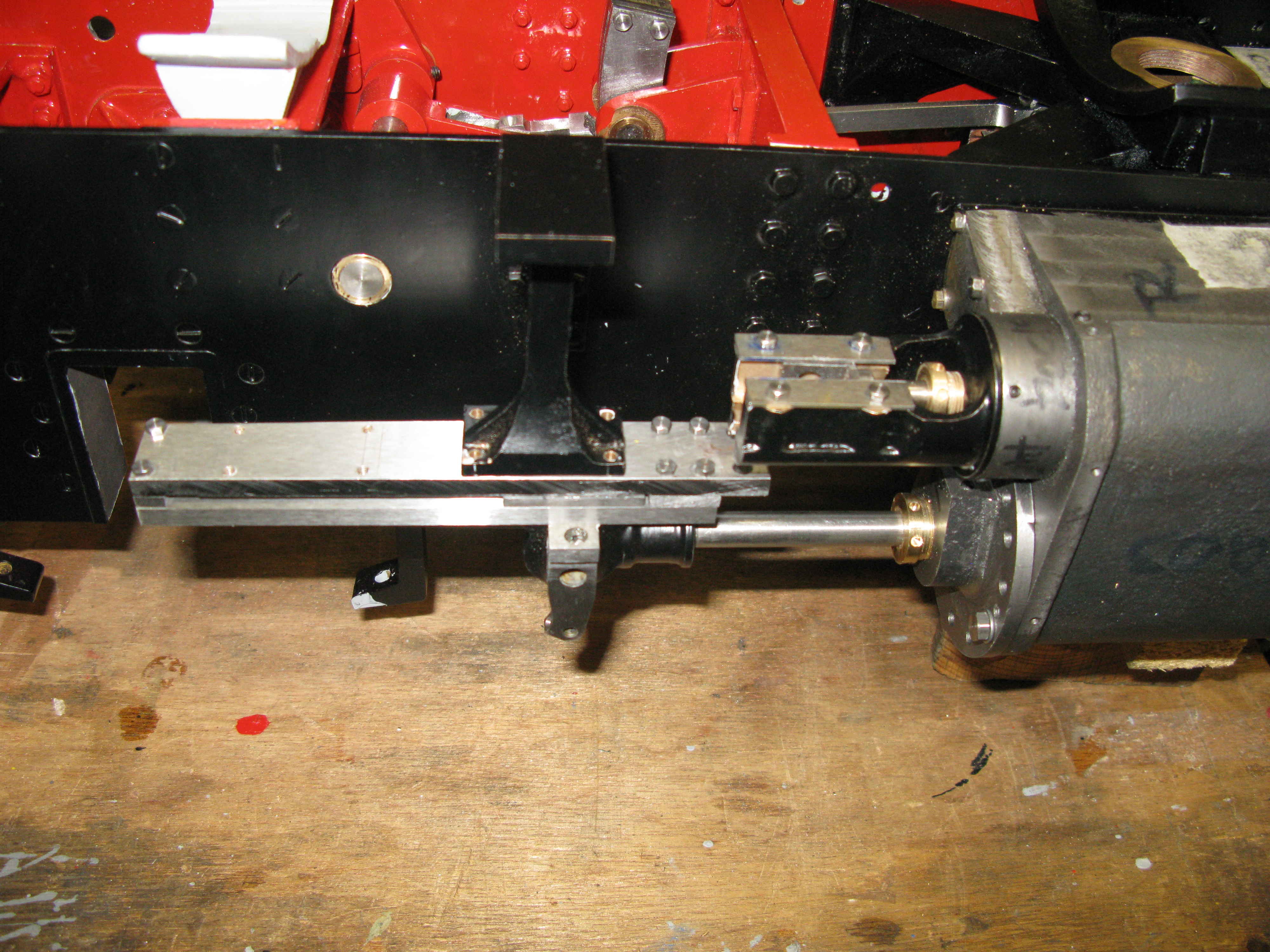
The first slide bar is complete and trial fitted as seen from the underside in the photo below.

The assembly process requires the rear 1/8″ square section to be fitted before the slide bar/cylinder cover assembly is slide onto the piston rod as the fixing screws at the cylinder cover end are inacessible otherwise. The outer 1/8″ square section is the last to be fitted and only after the cross head is in place but here it is shown fitted.
The second slide bar assembly is underway and has been fitted to the cylinder end cover to check the clearances to the support bracket and also its parallism to the piston rod.
There is only 3 thou difference in the space between piston rod and top slide bar from the first one fitted so I was quite happy with that. However the space between the top slide bar and the support bracket was much smaller than the first one fitted. Having checked the numerous dimensions that could affect the gap I am so far non the wiser why there is a difference. The cylinder block angles are the same as measured with a digital protractor on the top of the block, the support bracket has the same dimensions and is in the same relative position on the frames and as the gap between piston rod and slide bar is virtually the same, the cylinder cover fixing point is the same height. The one check I have yet to do is the cylinder block cover face relative to the frame just in case there is a variation in the parallelism of the bore to the block……….No that’s OK but in measuring this I realised that the dimension of the cylinder bore to the top of the block had not been checked, and therein lay the answer, the dimensions were slightly different for each cylinder. The cylinder I had completed the slide bar assembly for with the gap which I had attributed to a drawing error for the support bracket had its cylinder bore machined incorrectly by a few 10’s of thou away from the top of the block which was a reference face. How I came to do this I do not know, that was some months back. The question now was, does it matter.
Having looked at the drawings I think the difference in height of the cylinder bores relative to the wheel axle centre line will not be a problem for running, nor will it affect the valve operation to any great extent as all valve operations are relative to the valve and piston rod via the combination lever which remain the same only the radius arm to the expansion link angle will be very minutely different. So I am going to live with what I have.
Cross heads
AS I cannot sensibly get to the far side of the loco to finish off the slide bar until I have built my turnover frame I decided to start the cross heads.
The process is the same as the middle cylinder but the cross head outer part has a built in drop link that has to be machined into it. Other wise they are the same as the middle cylinder. Of course the critical dimension from centre line to the top of the cross head is not the same as the middle cylinder so my CNC drawing had to be altered to the size that matches the actual measurement.
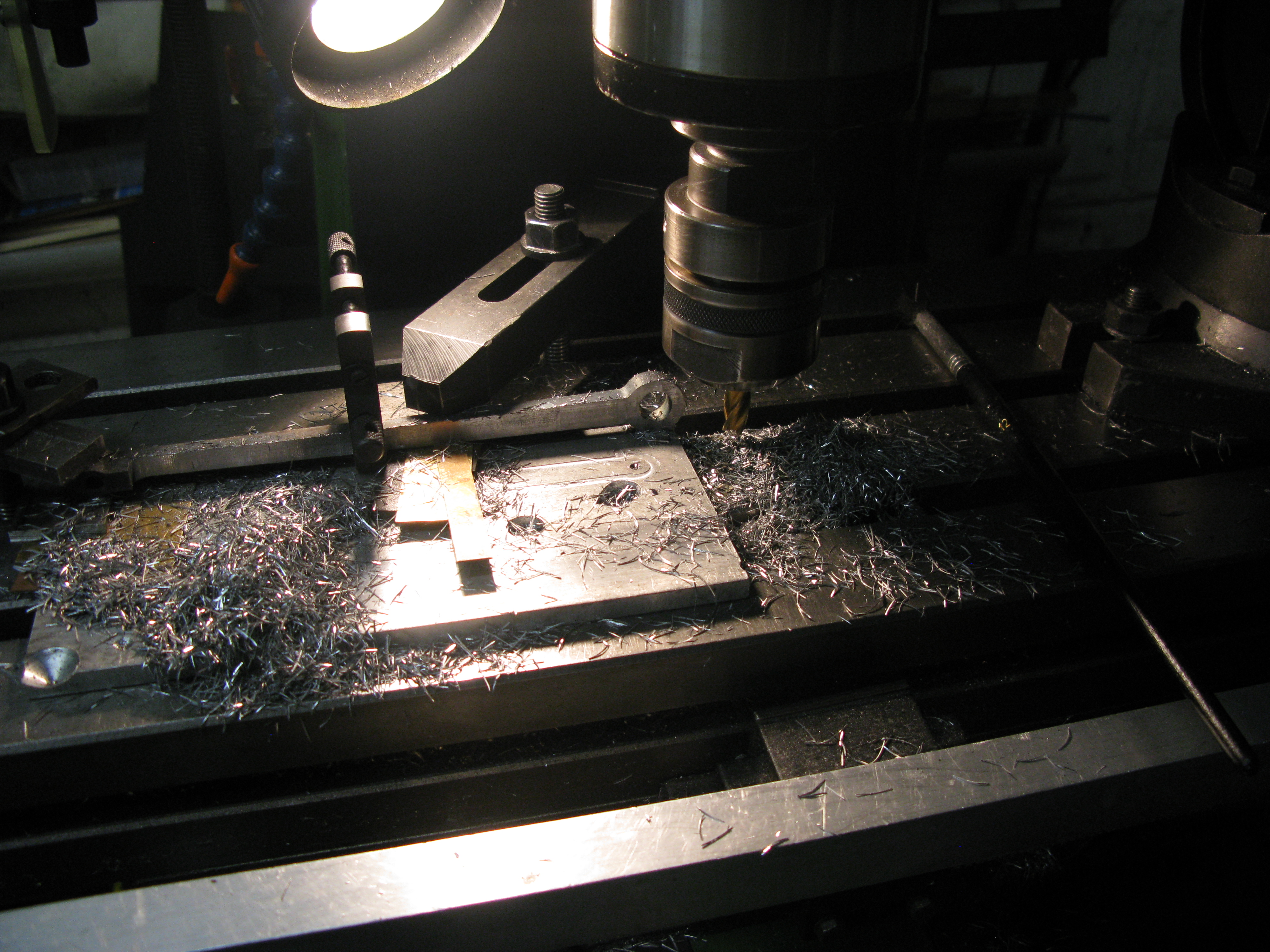
To recap, the first task was to mill the blank down by 3/16″ to form the slide bar T section on one side.

The machining has to be done in a couple of steps because of the clamping arrangement. In the photo above the first machining operation has been done and the clamp position changed so the second maching operation can be completed.
The next stage is to machine the cavity that forms the position into which the connecting rod small end fits. This is done on my little CNC mill.

Machining the small end cavity

A pair of cross heads with machined cavity
The sharp sighted amongst you will no doubt pick up on the fact the cross heads are both the same in the above photo and of course they should be handed! This is not a major problem as the soldered face will just be on the other side of the finished cross head. The second side has to be machined anyway to form the complete T form of the cross head.
Next task is to machine the outer contour which was done on my little CNC mill.

Change of plan having made two plates to silver solder onto the cross head to close the cavity I decided that the drop link would be made seperately and silver soldered in place. The drawing shows a recess in the plate onto which the drop link is fitted to take a PB bush for the gudgeon pin. I felt it was going to be difficult to get a bush into postion and fit so I made the hole for the bush full depth of the plate and it would be press fitted into place after the drop link was silver soldered on.

Machining one of the closure plates. The plate was sawn off and machined down to 9/64″.
To silver solder the closing plates in position I made a temporary close fitting pin with diameters to fit both sides and a thread to take a nut to clamp the plate being fitted in position which had been previously smeared with silver solder paste.

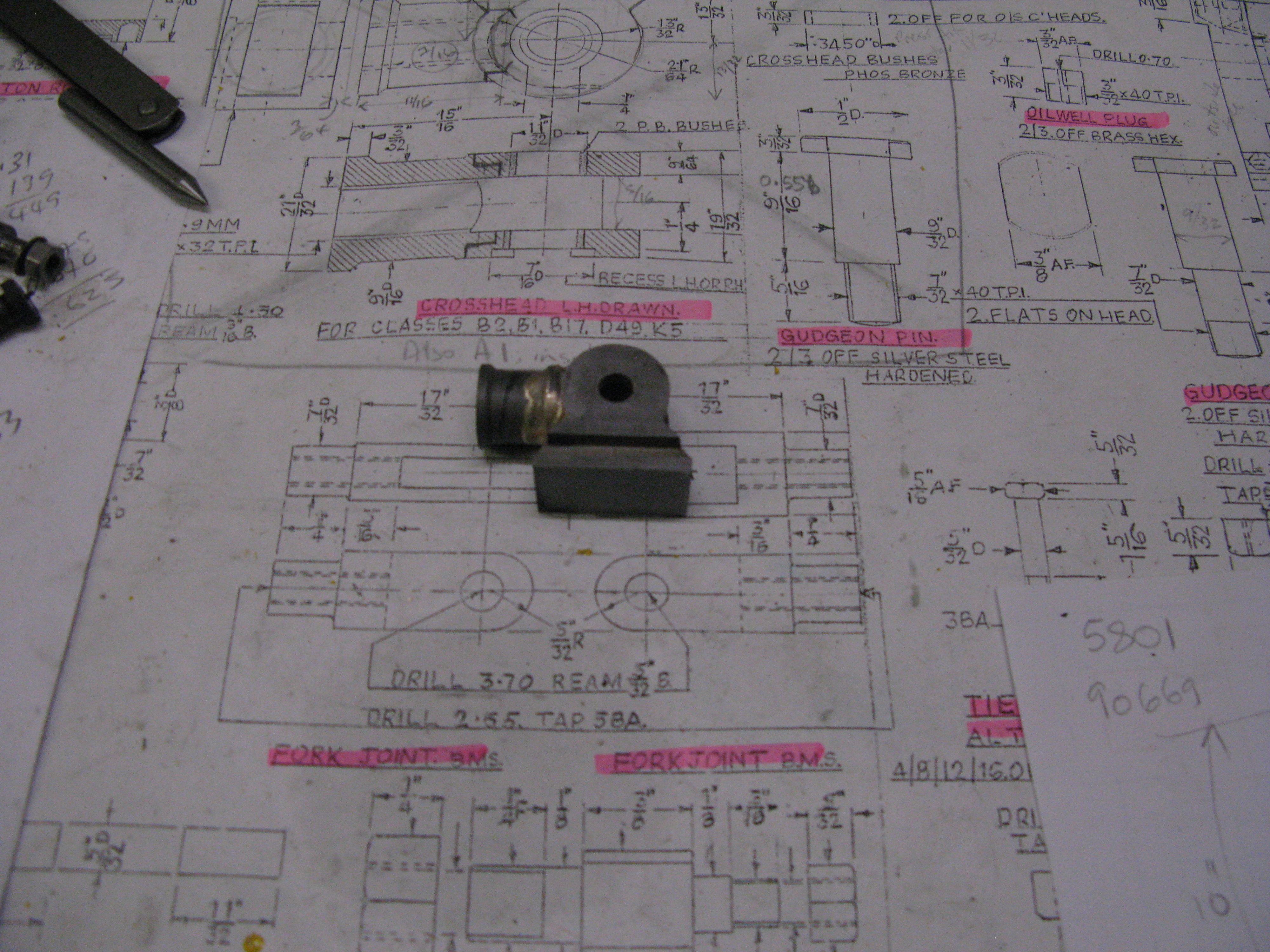
Cross head and closure plate with temporay pin to hold it all together

Once soldered the pin was removed and the plate holes drilled out to the bush size of 11/32″ OD.
The assembly then had the hole drilled for the boss that screws onto the piston rod. and a socket machined with a slot drill to take a spigot on the boss.

The boss that screws onto the piston rod is a straight forward turning exercise.

At this stage it is not threaded. The bush was clamped to the crosshead with a jewellers clamp and silver soldered into position. The closing plate was held in place by a temporary pin to ensure it did not move during the soldering operation.
The drop link was machined as a seperate item. It was made from gauge plate only because I had some 5/16″ thick available and I did not have any mild steel that thickness. The finished thickness is 19/64″. The machining was done on the cnc mill leaving a bit of machining to be done afterwards on a rotary table on the underside to match the curvature of the cross head. The drop link is silver soldered to the cross head and to hold everything in place I made a pin to fit into the cross head holes and the drop link hole with a 2BA thread on the end to take a nut and washer.

Not too clear … CNC machining the drop link
Before soldering it in place the oiling hole for the bottom pin was drilled and tapped 8 BA. The drawing calls for 3/32″ x 40 ME but such a size is not readiliy available it would seem.
The drop link had silver solder paste smeared onto the mating surface and to ensure no solder flowed onto the securing pin it was coated in tipex around the joint.
A fillet of silver solder was also run down the edges of the drop link when the paste flowed to ensure a sound joint.

The hole for the top oiler in the drop link was drilled as drawn (1/4″ x 40 ME) and found to be wrong as a tap will not pass the upper slide plate of the cross head edge. Also the brass hex insert will foul the slide bar. I will have to think of a solution to this problem for the one cross head, the second cross head will be 3/16″ x 40. The oil hole at the bottom of the well is drawn to come out inside the cross head to lubricate the gudgeon pin bearing and to get the angle to do this the hole has to be drilled from the outside surface of the drop link and then the hole pinned and silver soldered to seal it up.

drilling the oil hole
Finally the gudgeon pin bushes are fitted. To press fit the inner bush I made a tool that would align the bush correctly with the recess and that made the fitting easy. Both bushes were loctited in place.
With the cross head painted it was fitted to the piston rod. To do this entails moving the rod to a position where the cross head can turn without fouling either the valve guide or the slide bar bracket.

Next the slide bars are assembled onto the cross head, and again this requires the piston rod to be positioned so there is access to the fixing screws for the underslide slide bars.
Having done this the cylinder block cover plate can be bought forward so the slide bar can be fixed to it with the required shims so it bolts down level.

Finally the cover plate is bolted back onto the cylinder block and the slide bars bolted to the slide bar bracket.

Coupling rods
The coupling rods (side rods) are machined from 3/8″ thick by 1 1/4″ mild steel. I tackled the front rod first and the initial task was to determin that that the wheel centres and their pins actually matched the as drawn dimension for the rod. To do this I used my trammels and with one wheel fixed, gently moved the other wheel to feel the pin as it passed the trammel and then measured the result and adding half the pin diameters and the result was, I am glad to say, spot on the as drawn dimension of 7 11/16″.
This was not to be taken for granted that the rod would actally fit when machined so my plan was to machine the rod blank and drill and bore for the bushes, make and temporarily fit the bushes and then see if the rod fitted OK before embarking on more machining of the rod. This way if there was a problem of fit I could adjust the bores of rod that take the bushes and make a new one, or pair slightly oversize to the new pin centre dimensions to achieve free movement. I could then continue with the machining of the rod safe in the knowledge it would fit OK.

Machining the rod blank on my little CNC mill
Once I had the blank, I transfered it to my larger mill as the small mill was not capable of managing the large boring operation for the bushes, coupled with the fact I was not confident of attempting to get a good bore finish by a CNC produced milled hole. Without contiuous coolant flow to get rid of swarf from a slot a good finish is not really achievable. The outside of the rods would all be polished by hand so a good finish would be the hand finish.

Drilling for the two bushes prior to boring.
The finished bored holes for the bushes.
Having completed the machined blank I made the the bushes for each end. The driver end has no play in the fit but the other end has about 3 thou to allow for the springing movement.
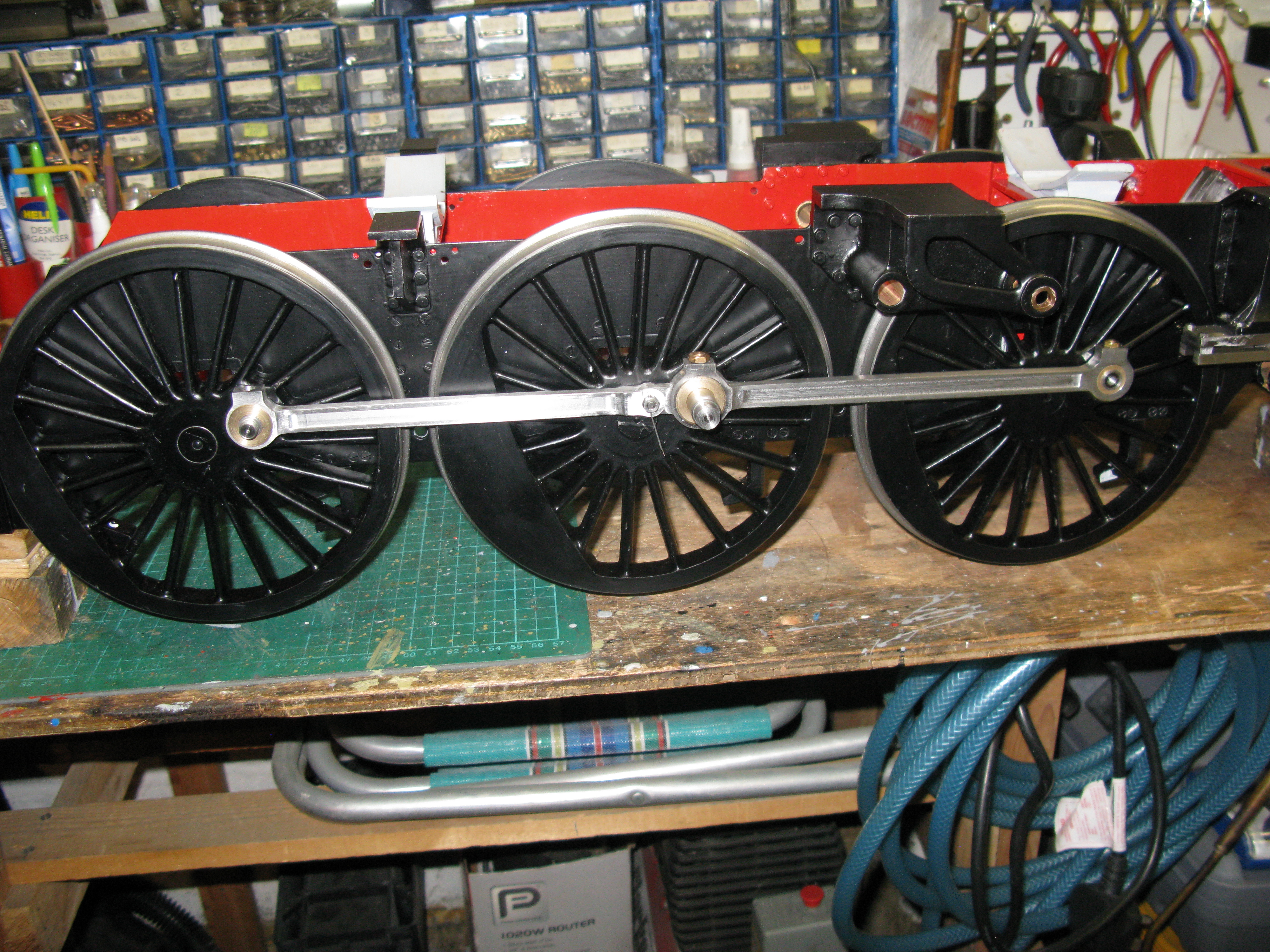
A trial fit of the blank onto the wheels was successful.

The wheels did turn but at the top dead centres were “lumpy”. This was, I hoped, entirely due to not having the other side coupling rod on to pull the wheel over top dead centre.
The second coupling rod was made to the same build standard and fitted to the other side. Fortunately the as measured centres proved OK and the rod slipped onto the pins OK. However when turning the wheels they jammed at top dead centre. They could be forced over with some pressure so it was supposed that more clearance was needed on the front bushes. Both were opened up to 5 thou clearance and this proved to solve the problem with the wheels turning reasonably well.
The play in my axle boxes in the horns is minimal, just sufficient for them to slide down under their own weight so I do not want to change clearances there. Whilst 5 thou is probably not excessive the as drawn clearance is 3 thou. I will wait until I have fitted the rear coupling rods before deciding whether or not to open up the clearance that little bit more or fit an oversize front bush with its centre a couple of thou or so shorter as that seems to be indicated by the movement of the pin in the bush.
Onto finish machining the coupling rod. The first task was to mill the rebate on the outside of the rod to thin it down to 5/16″ thick up to the main drive boss.

Relieving the rod .. .it is mounted against a fence to hold it parallel on the table
The flute was then machined with a 1/4″ woodruff cutter.
The rod was then turned around to relieve the back of the rod to give a 7/32″ thick rod.
To finishe machining the knee the rod was put onto a rotary table and the arc machined to finish of the drive end boss.

Having done that the knee was reduced in thicknes to 3/16″ by area clearing top and bottom.

The last maching jobs were to drill and tap for the oilers. The drawing calls for 5/16″ x 40 ME for the large end and 1/4″ x 40 ME for the other end. However these dimensions would not allow for the normal hex oiler inserts to be machined without them either being over size or the threaded portion not fitting across the flats is smaller hex was used.
I chose to make the sizes smaller, fitting 1/4″ x 40 ME at the large end and 3/16″ x 40 ME at the smaller end. The oil holes was first drilled 1/16″ and then opened up for the correct tapping drill 1/4″ deep.
Looking at the Tornado A1 the oilers are all part of the machined rod and stopped off with a cork. Mine will be the more traditional brass hex with a scalloped top.
Having done all the machining it was now time to hand finish. The initial finish was done using a Dremmel high speed drill with a small 3/16″ stone. The drill mounted in a stand for rigidity allowed the rod to be dressed by hand against the stone for the all the edges but not the sides. The sides were draw filled with a fine file. Lastly the surfaces were finished with emery paper.
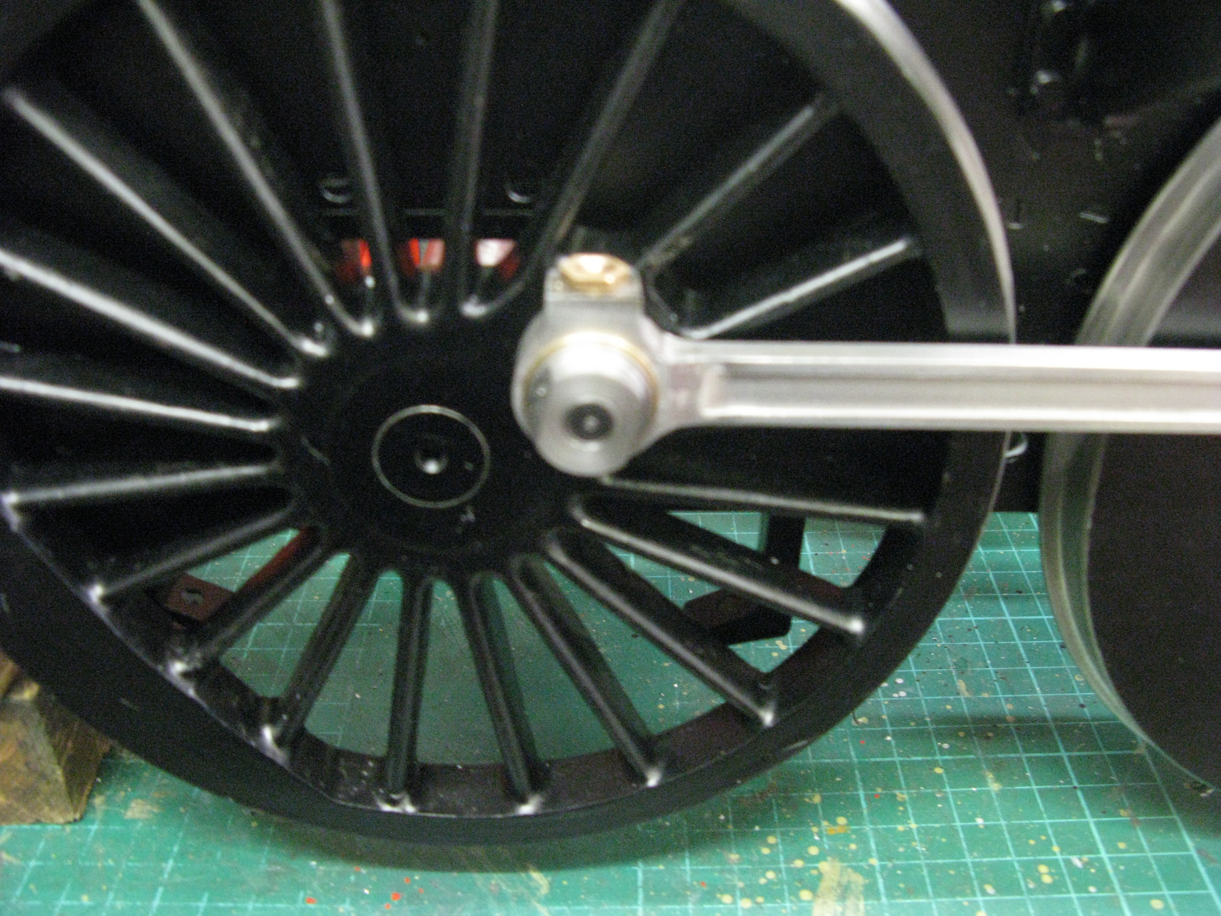
A completed rod – minus its oilers
The trailing wheel rods have been a bit of a nightmare. To read the saga it’s recorded in the diary notes. Once I have the two rods complete the pictures will be posted here. Basically the machining process is the same as the front rods.

Machining the blank for the trailing coupling rod
The blank rod is first machined on my little CNC mill as can be seen above. Once the blank is made the knuckle hole is drilled and reamed 1/4″ and the wheel pin hole drilled and bored 9/16″ for the PB bearing.
Boring the hole for the wheel pin bearing
The next operation is to slot the knuckle joint with a slitting saw. It is a 3/16″ wide slot and took two cuts using a 1/8″” wide saw.
Cutting the knuckle joint slot.
The rod was then thinned down both sides to give it its 7/32″ thickness and fluted on the outside in a similar machining operation as the front rods.
The rod was trial fitted to the wheels without the PB bearing and using number drills I established that the gap between the pin and hole was more or less even front and rear so the PB bearing bush was made to fit with a 3 to 4 thou clearance and pressed in place. The rod refitted and the wheels test turned and found to be OK.
The second rod was then made to the same dimensions and when fitted the wheels turned OK.
The retaining nuts for the rear wheels are a straight forward turning job whith the two flats being milled once the turning and threading is completed. The retaining screw for the front wheels is essentially a PB washer with a 2 BA C/S allen screw head to fit flush.
The oilers on the rods are not as prototype but are brass hex with a mild counter sunk top as an aid to practicality to oiling up.

Now all the rods are OK I can think about pinning the wheel sets onto the axles
Connecting rods
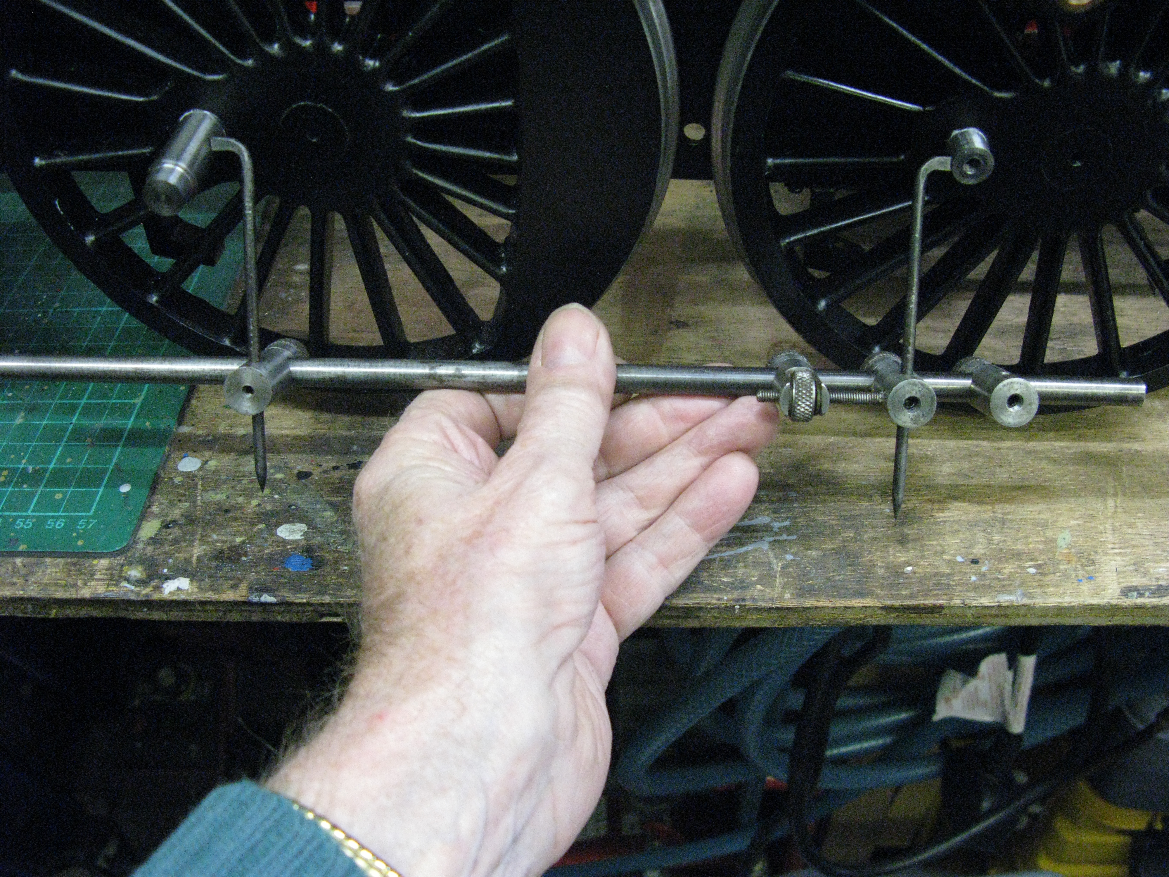
The Conecting rod is dimensioned on the drawing as being 12 7/32″ between centres but checking the scale drawing it appears to be drawn at 12 1/8″. A check on the actual locomotive using a sliding rod measuring device showed with the piston fully forward and the wheel set on front dead centre and the measuring device set to fit between the wheel pin and gudgeon pin and then with the piston full back and the wheel set on rear dead centre the gap between the two measurements was 0.048″. So the rod length between centres needed to be the measured length plus half the pin dimensions and plus half the gap. This worked out as 12.113″ which is very near 12 7/64″ ( 12.109) so I concluded the written dimension was in error. Of course the cross head could be moved by screwing it on or off the piston rod but not to the extent of getting another 7/64″ on the length.
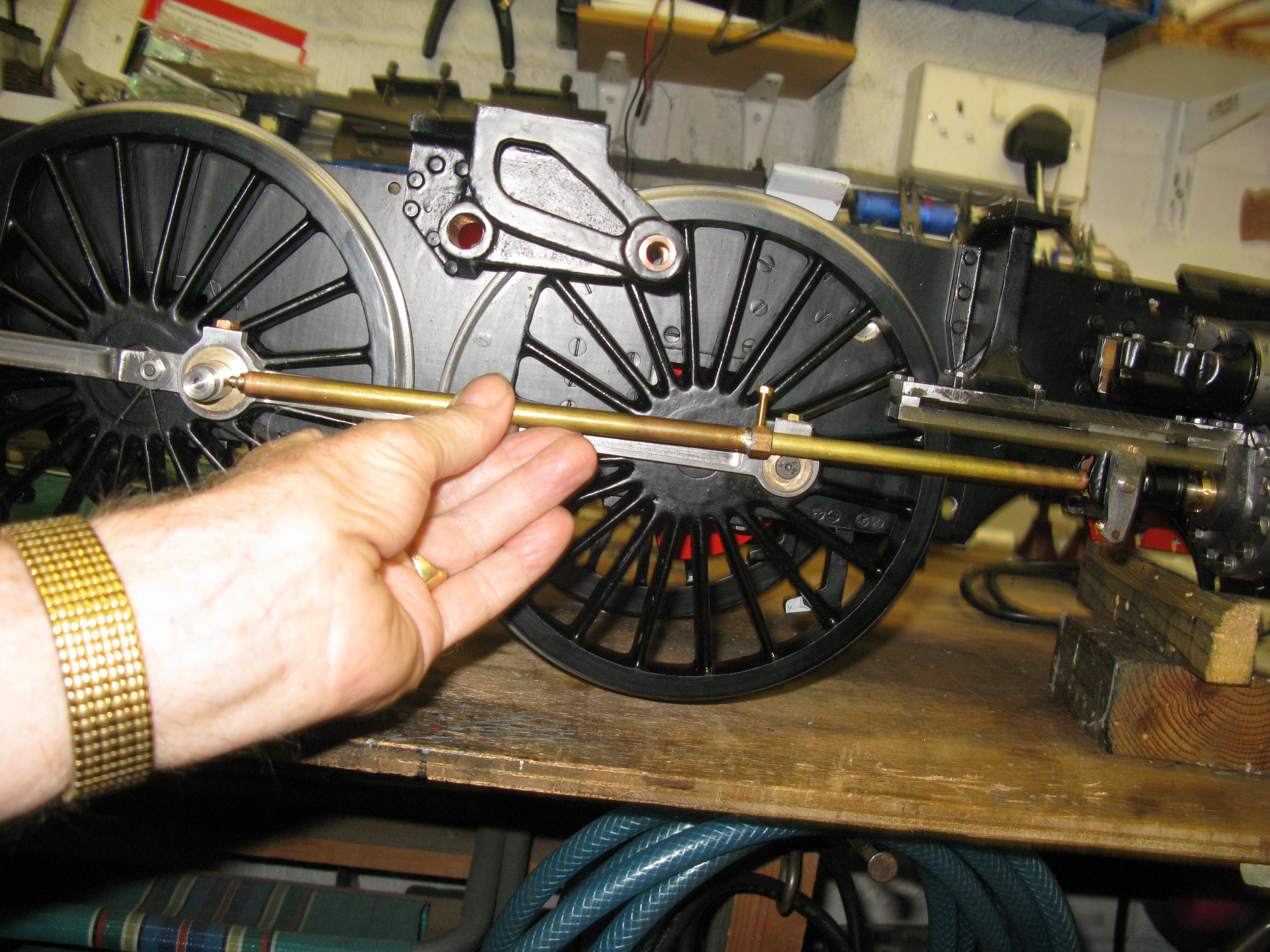
Using a sliding rod to check the length of the RH connecting rod
Having measured the connecting rod length I felt it prudent to double check by making an adjustable connecting rod to verfy that the motion would turn over without the pistons jamming up at the front and rear dead centres. It’s a simple device as can be seen in the photo below.

Having successfully turned the wheel set over with it fitted I put the check rod onto the mill table to measure the centres with the DRO and it was within 0.003″ of the sliding rod measurement so all was well.
The overall length of the connecting rod is too long to machine it in one operation on my little CNC mill so I decided to set out the centres of the big end and little end on my normall mill and put in a 1/8″ pilot hole in each centre. Having done this I can now transfer it to the CNC mill and machine the big end profile and then afterwards reset the work on the table and machine the little end profile. The work can then be put back on the normall mill and set up to machine the rod length top taper and then reset to machine the botom taper.
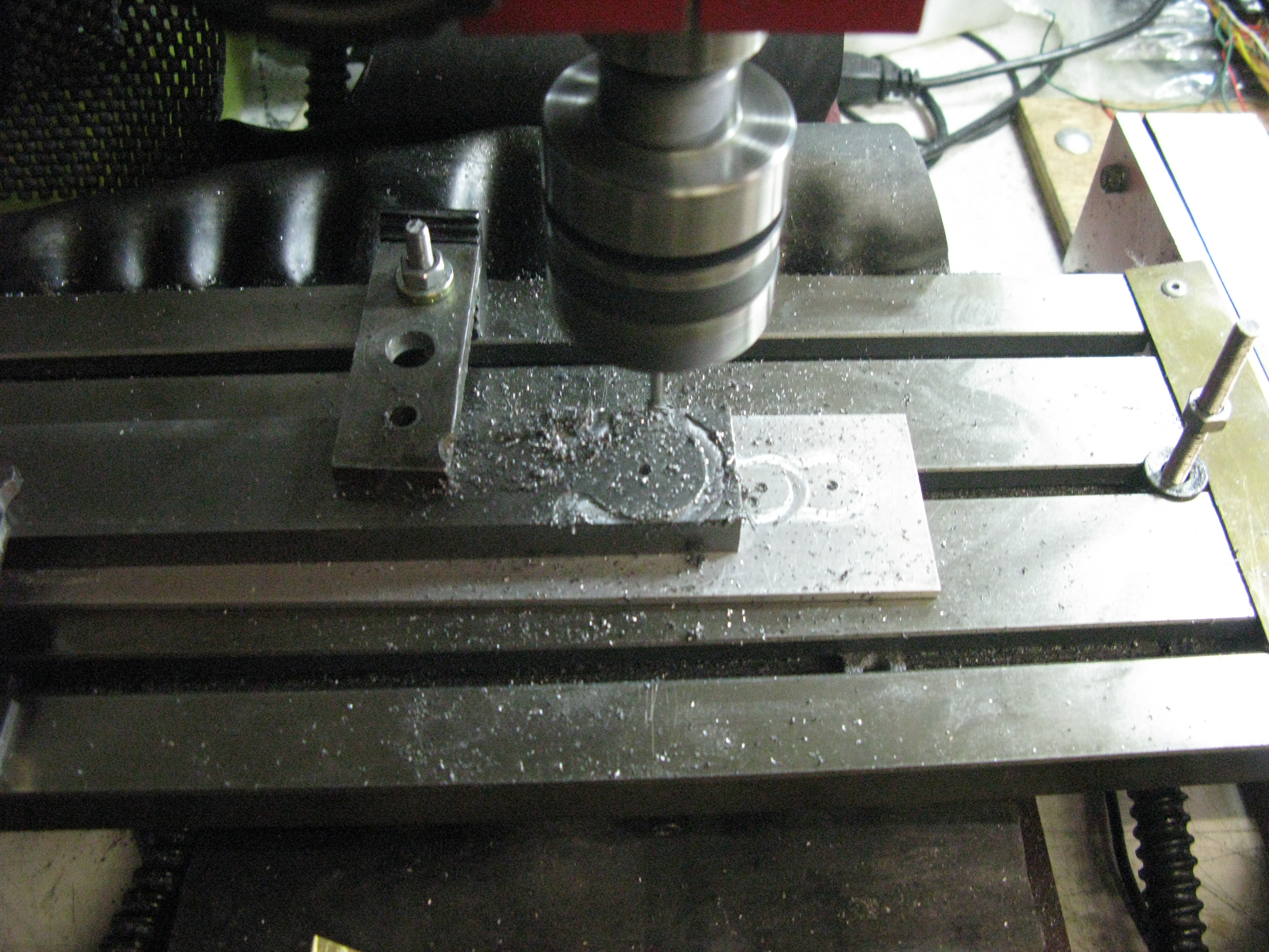
Machining the big end profile

Machining the little end profile
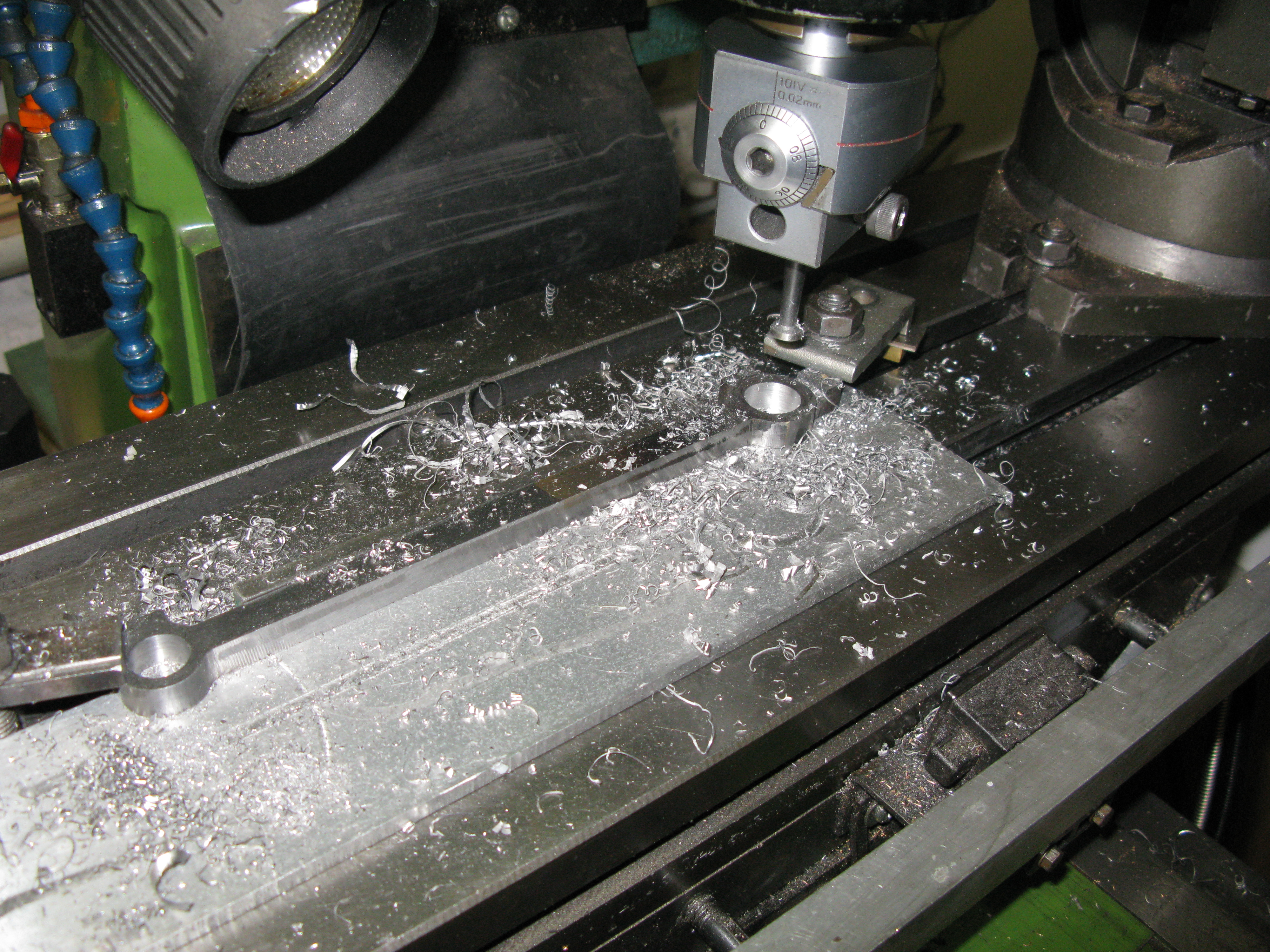
Machining the top and bottom tapers
The top and bottom tapers were first scribed on the material and then the material aligned on the mill table so the tool followed the scribed mark. The bottom taper was then cut. The top taper followed the same set up and the photo above shows the top taper being cut.
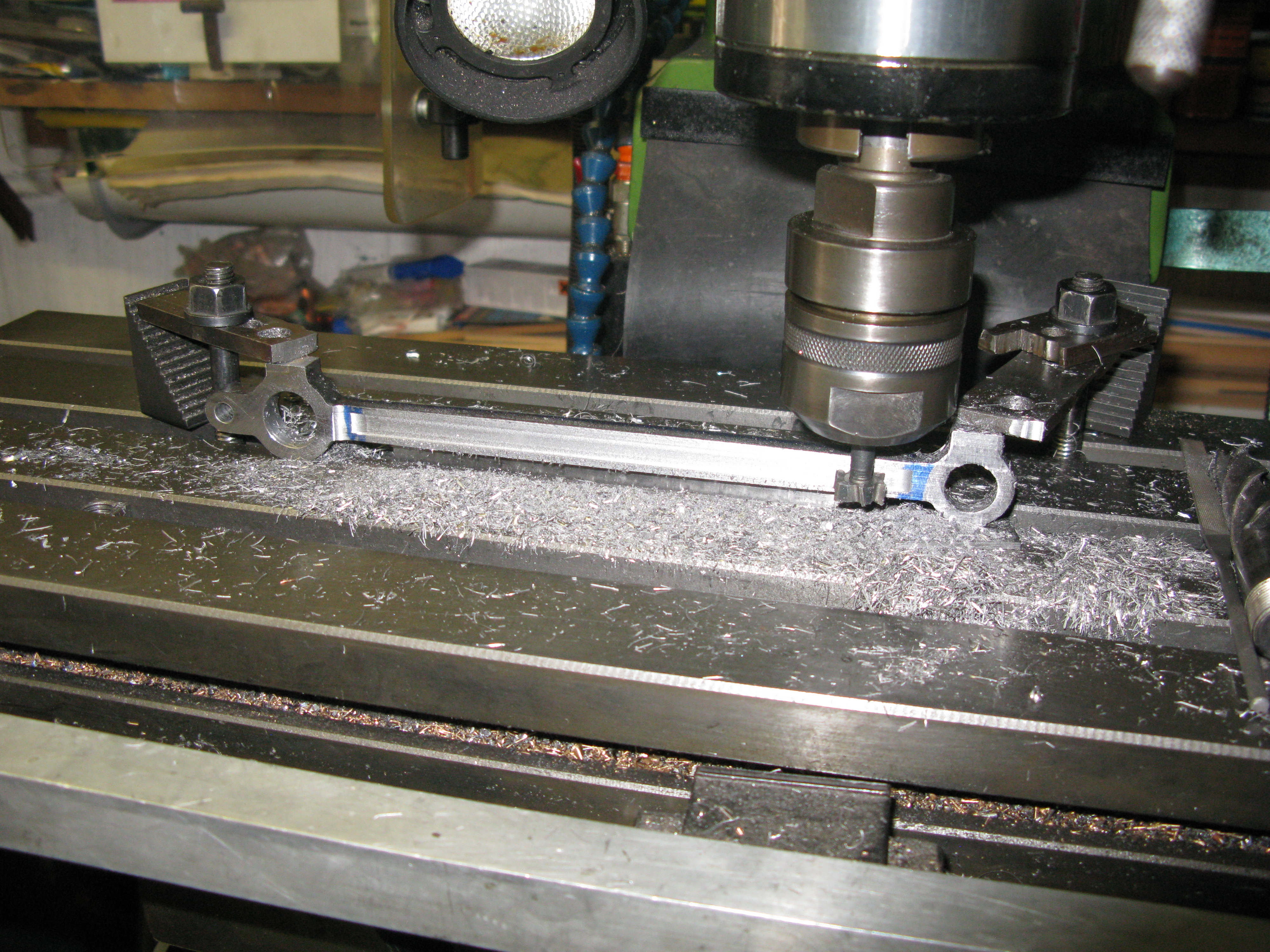
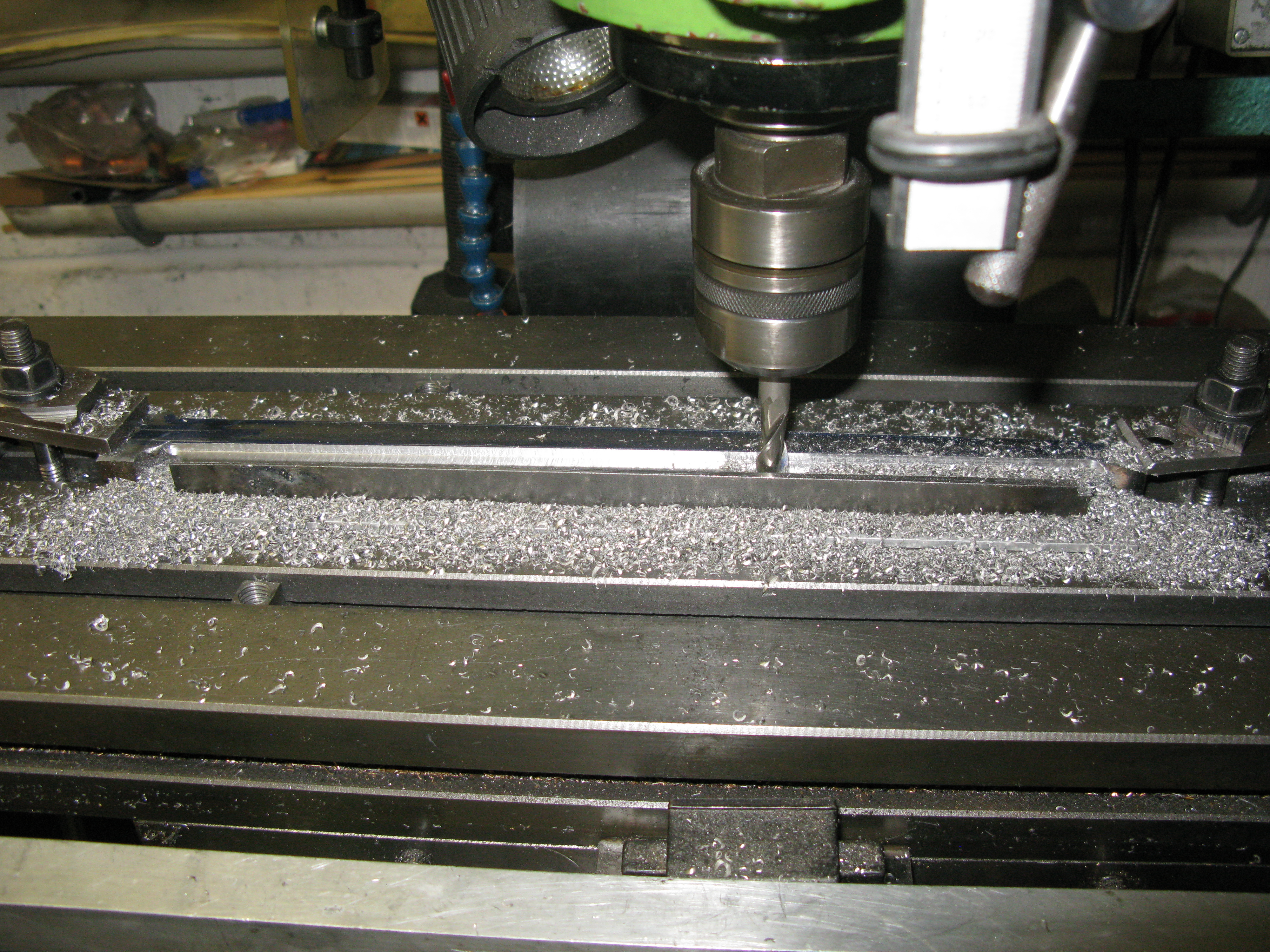
The rod was then set up against a fence to machine the relief on the front side of the rod. The rod is clamped down to the mill table with the little end packed up so the centres are parallel to the table top. The front relief is 1/8″ and to prevent the rod bowing as the inbuilt stresses are relieved by the cut, two clamps were used in turn to hold the rod against the fence. As the cutter moves up to the first clamp the second clamp is fixed behind the cutter and the clamp in front of the cutter then removed. This process is repeated for each pass of the cutter.

Machining the front rod relief
With the front relief finished and the rod off the mill it had a distinct bow over its length due to the stresses but I thought that when the other side relief was cut much, if not all of the bow would come out naturally.

So, setting the rod up on the mill again to cut the rear relief using the same process of clamping the rod against the fence ensured it was going to be cut parallel.
Once done, sure enough much of the bow had gone, however it was likely that the bow would come back when the 1/16″ deep flute was cut.
The next task was to bring the little end down to 5/16″ wide to match the rod.
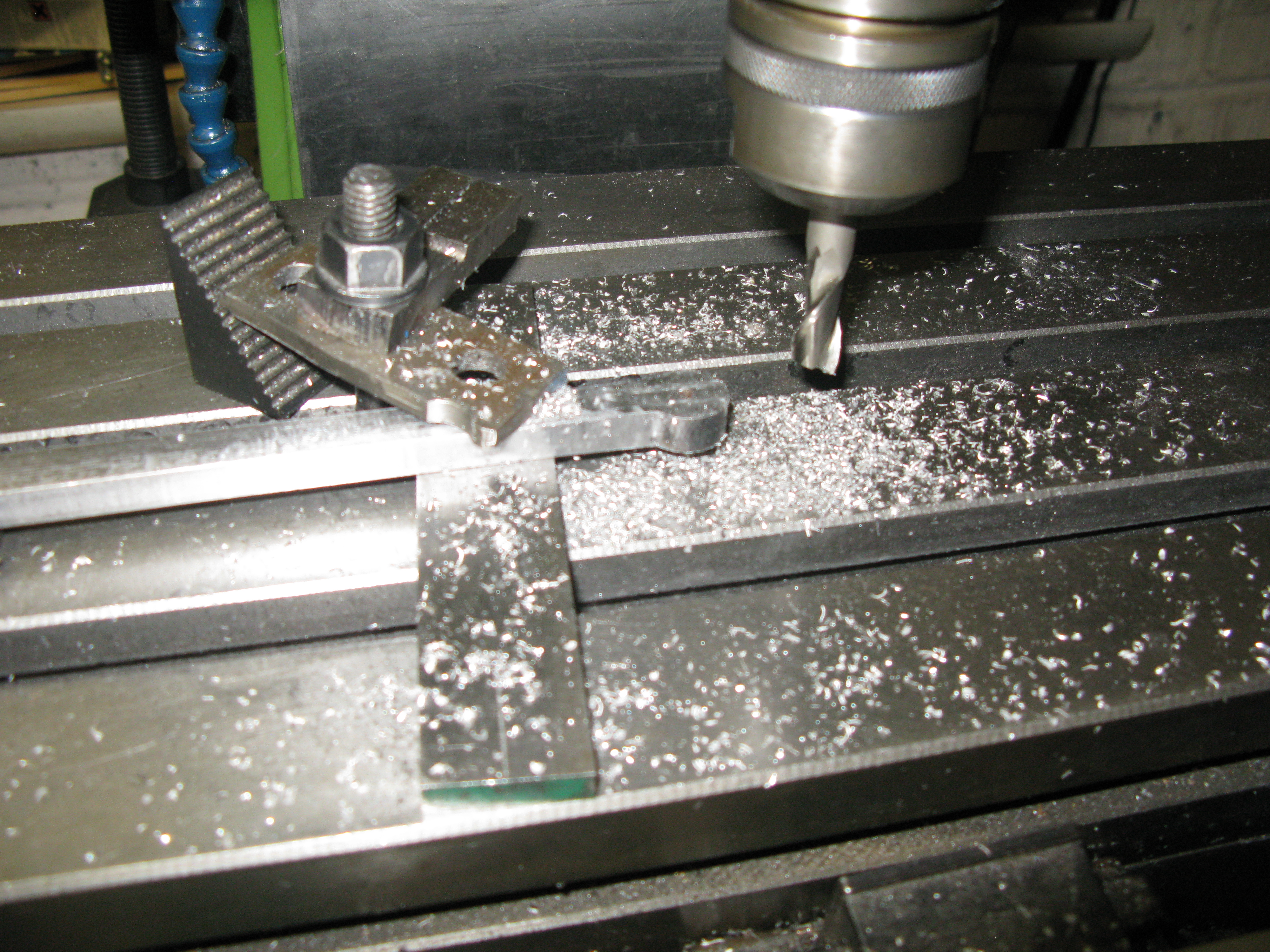
Thinning the little end
Before cutting the flute I drilled and reamed the little end to accept a PB bush and bored the big end to take the big end bush.
Boring for the big end bush
The flute is tapered along its length so as to be parallel with the top and bottom edges of the rod. I used a 1/8″ by 1/2″ woodruffe cutter to cut the flute having first set up the rod so the top edge was parallel to the mill table and cutting to full depth over a number of passes and the turning the rod over and again making the bottom edge parallel to the mill table cut another number of passes to full depth. Another two operations were then needed to remove the material left inbetween the the two slots cut.

Top slot cut and the bottom slot in the process of being cut
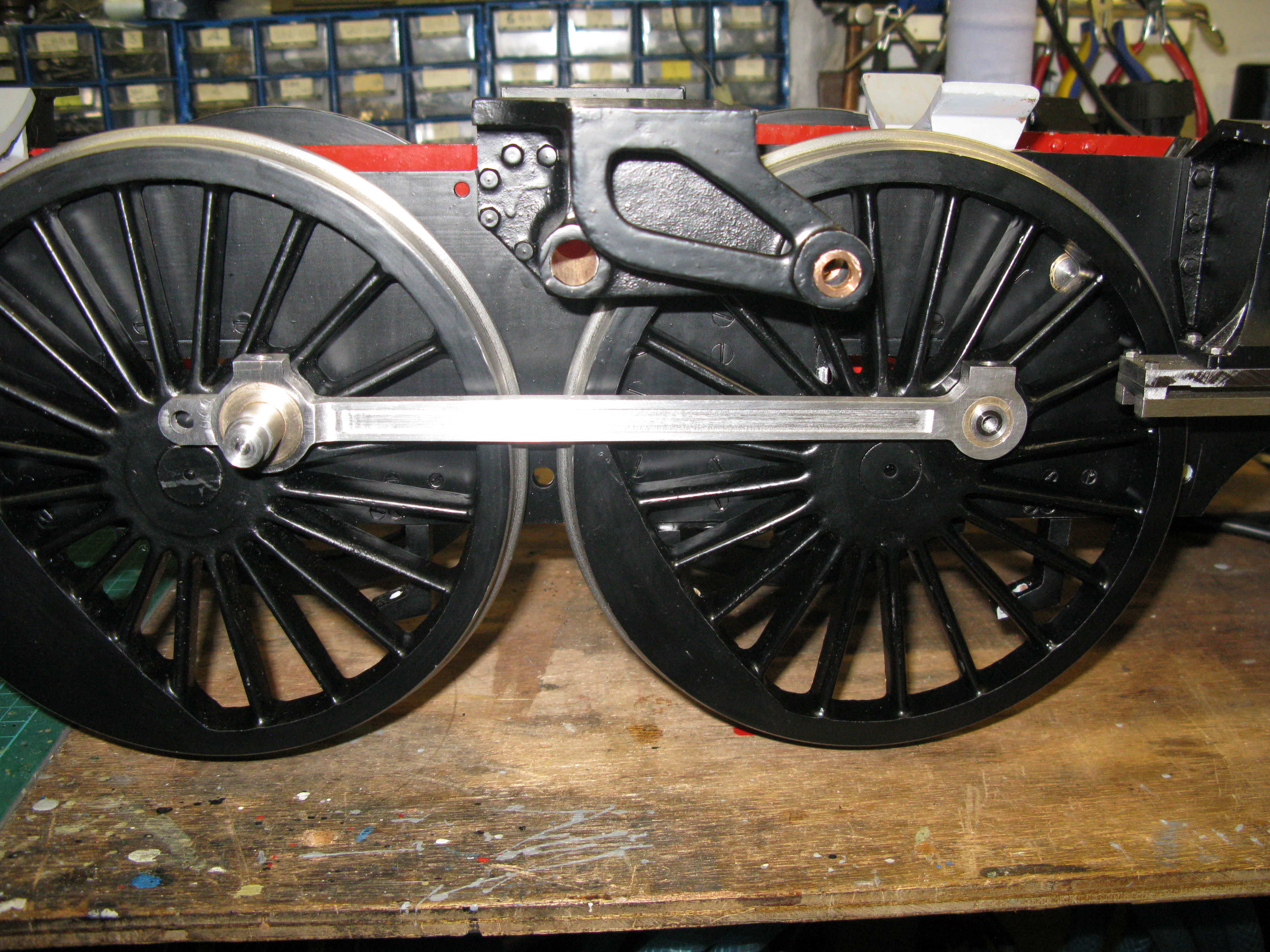
The flute did indeed cause the bow to return and my method of restoring the rod to be straight was to use my hydraulic press and carefully bend the rod over a number iterations checking after each one to see how much bow remained. The rod was simply rested on two steel blocks, one at each end and the press applied to the middle and towards the big end depending on how I perceived the bow to be moving towards becoming straight. The final check on whether it was straight came with fitting it to the wheel set and seeing if the little end freely entered the crosshead ……. which it did.

The fitted rod
Did the wheels turn over and drive the piston OK without any jams?…….Yes.
The second connecting rod was a saga of problems, all minor, but nevertheless extending the time to make it. I think it was one of those weeks when nothing goes right.
Anyway it is complete but one mistake that I could not correct was machining the flute a little to deep. I do not think it is that noticeable, unless you know about it of course………
When fitted the piston came up against the rear cover but was all right at the front. It turned out to be only a fraction so I chose to turn off 20 thou from the cover face to cure it.
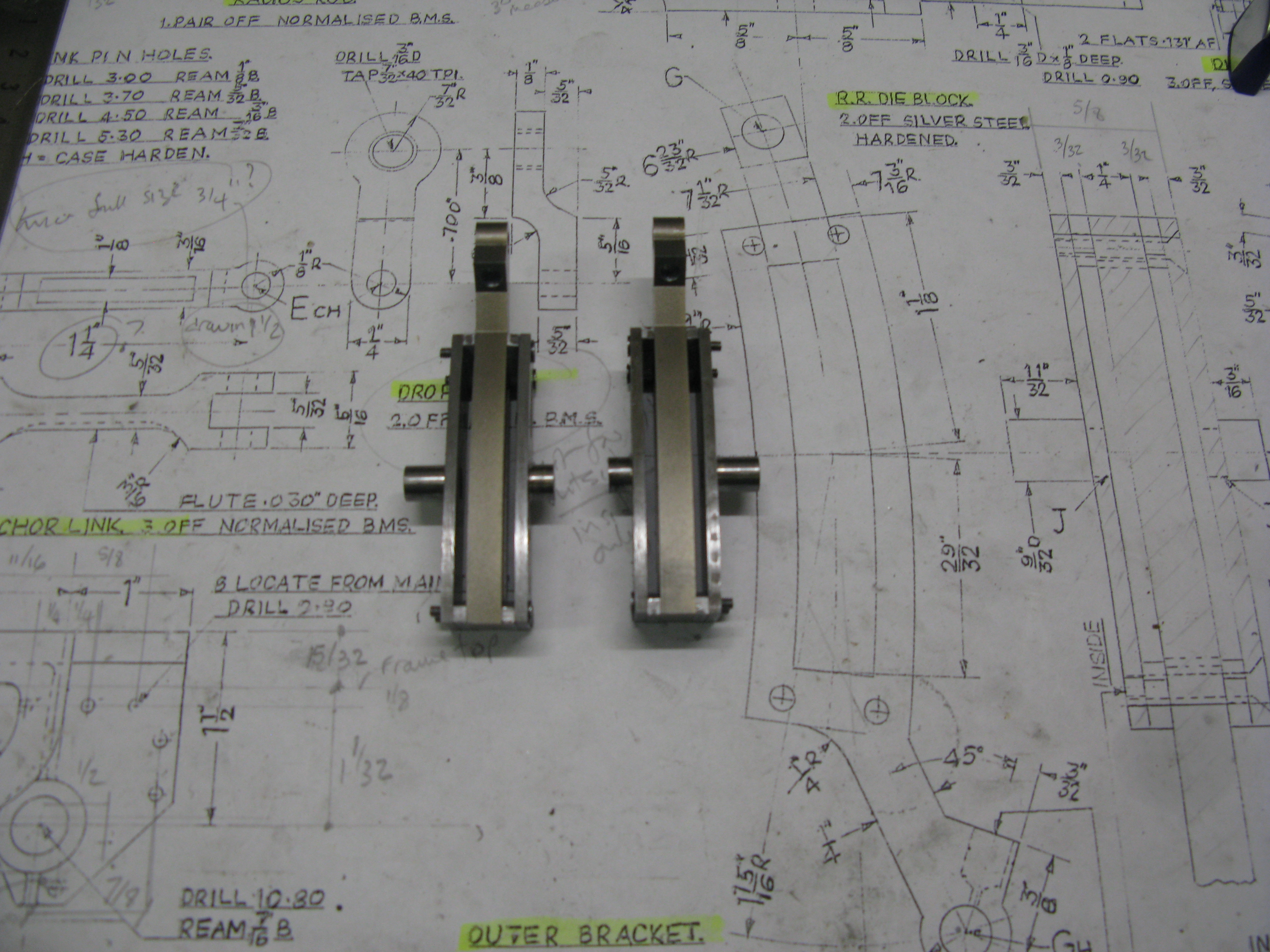
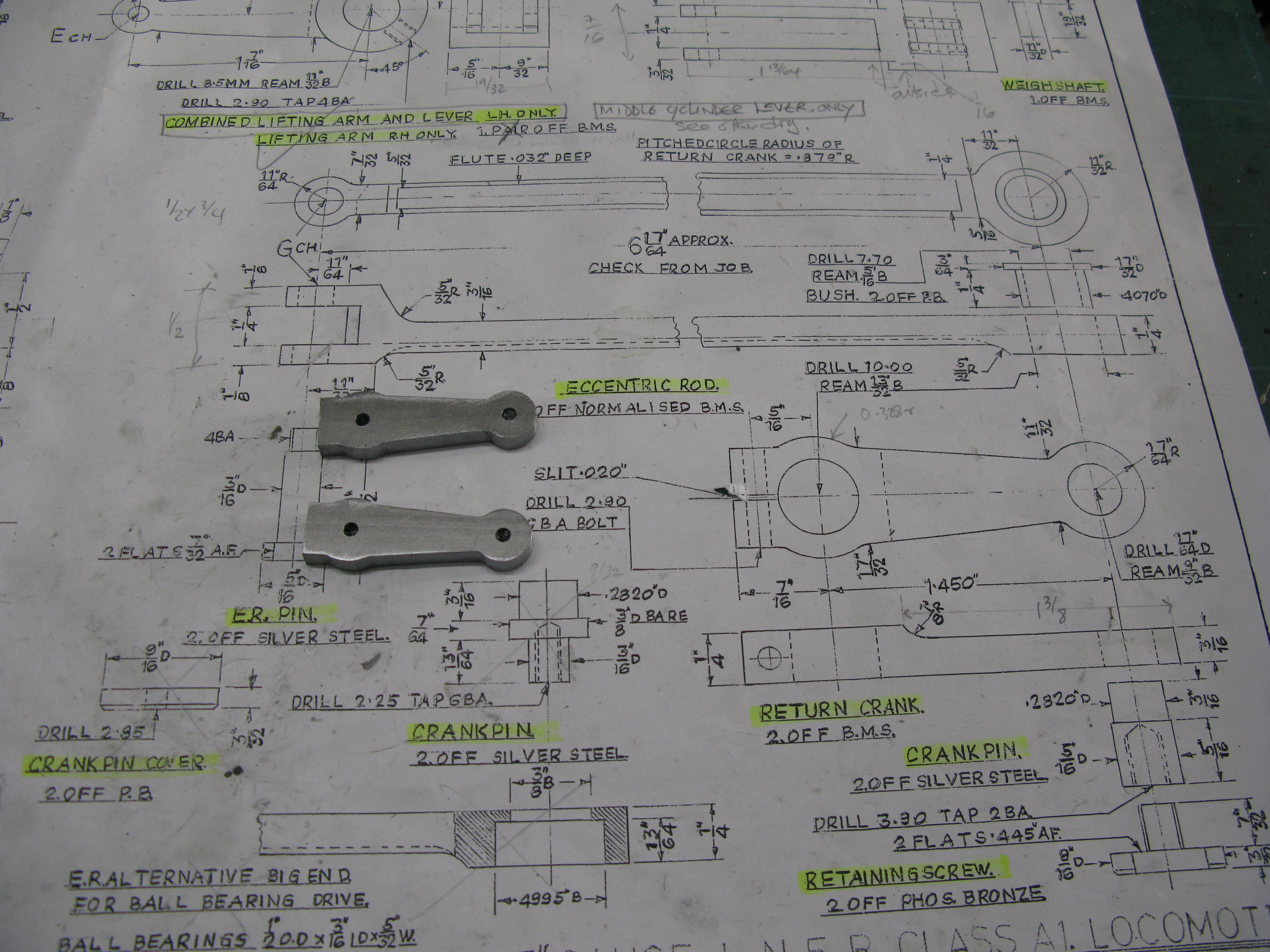
Expansion link
I dreaded making this item as I had so much trouble in machining the inside expansion link. To recap, the link is made from 1/4″ gauge plate and it plays havoc with the tools. Anyhow I set the CNC mill up to do the machining and 3 hours later and three broken tools I gave up. I decided to have the link wire cut professionally and the quote I received was cheaper than buying all the new tools that I had purchsed to mill them myself! Must be a lesson there.
The outside plates are from mild steel and theses were able to be successfully cut on the CNC mill.

profiling an expansion link side plate
The outside plate has two slots in it and the inside plate has the corner fixing holes tapped 7 BA to accept the c/s fixing screws.
The pair of side plates completed
The trunnions are from silver steel and silver soldered into the plates. Trunnions are 11/32″ OD with a 7/32″ OD x 3/32″ pip to filt into the plate. The holes in the plates that accept them are slightly chamfered so that the silver solder runs into the gap produced to get a firm fixing.
check assembly in the bracket
Having put them into the expansion link bracket to check they turn freely I found that the inside measurement was less than the 7/16″ required to fit the expansion link and spacers. About 0.020″ has to be removed (some of it paint!)…..another filing job, but I will await the delivery of the wire cut expansion links first.
The link is seperated from its outside plates by 3/32″ thick spacers so eight of them are required to do both sides. A little job for the CNC mill but still time consuming to do the drawing and do the cutting.

A pile of spacers with two over the drawing in place.
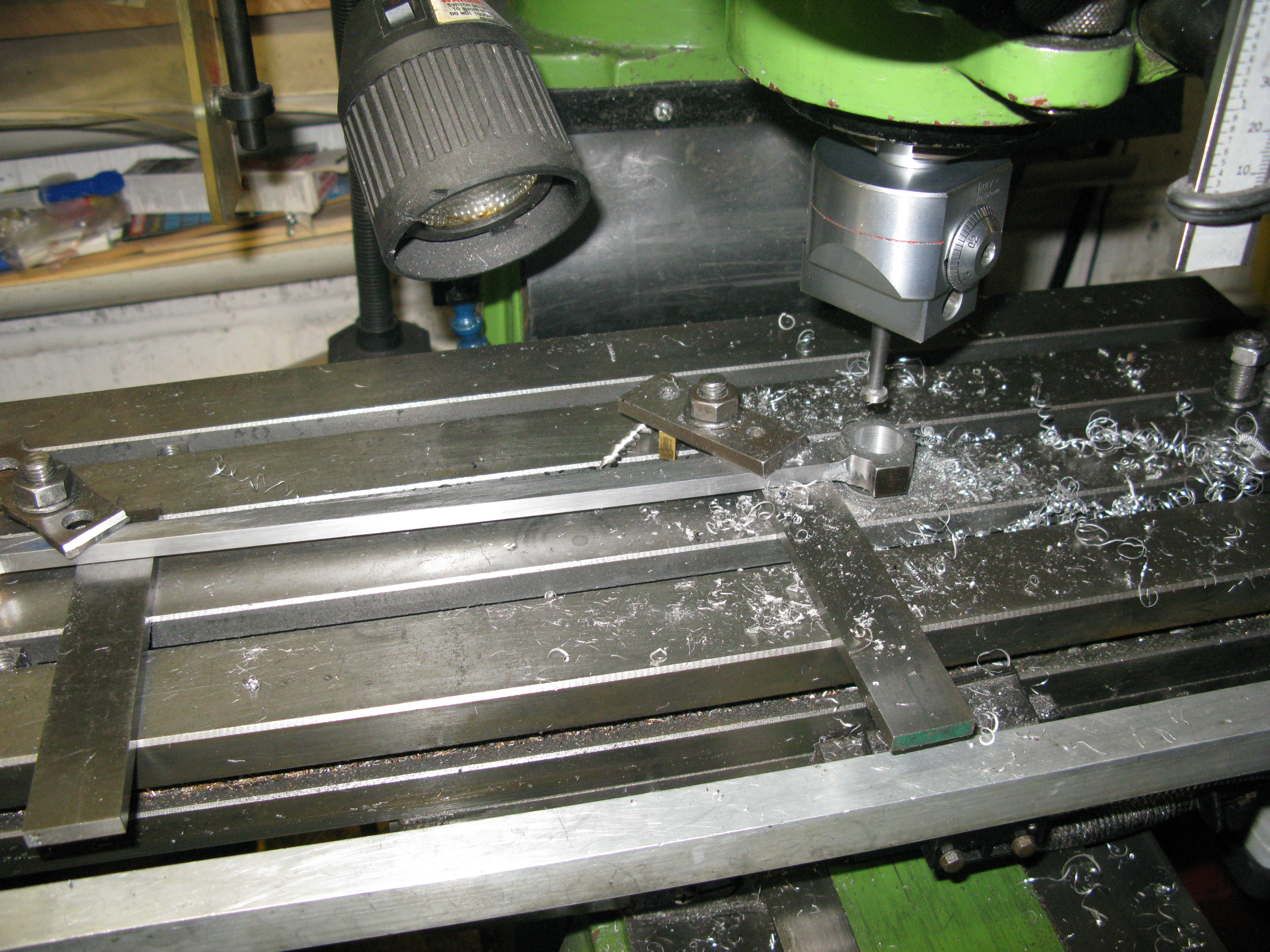
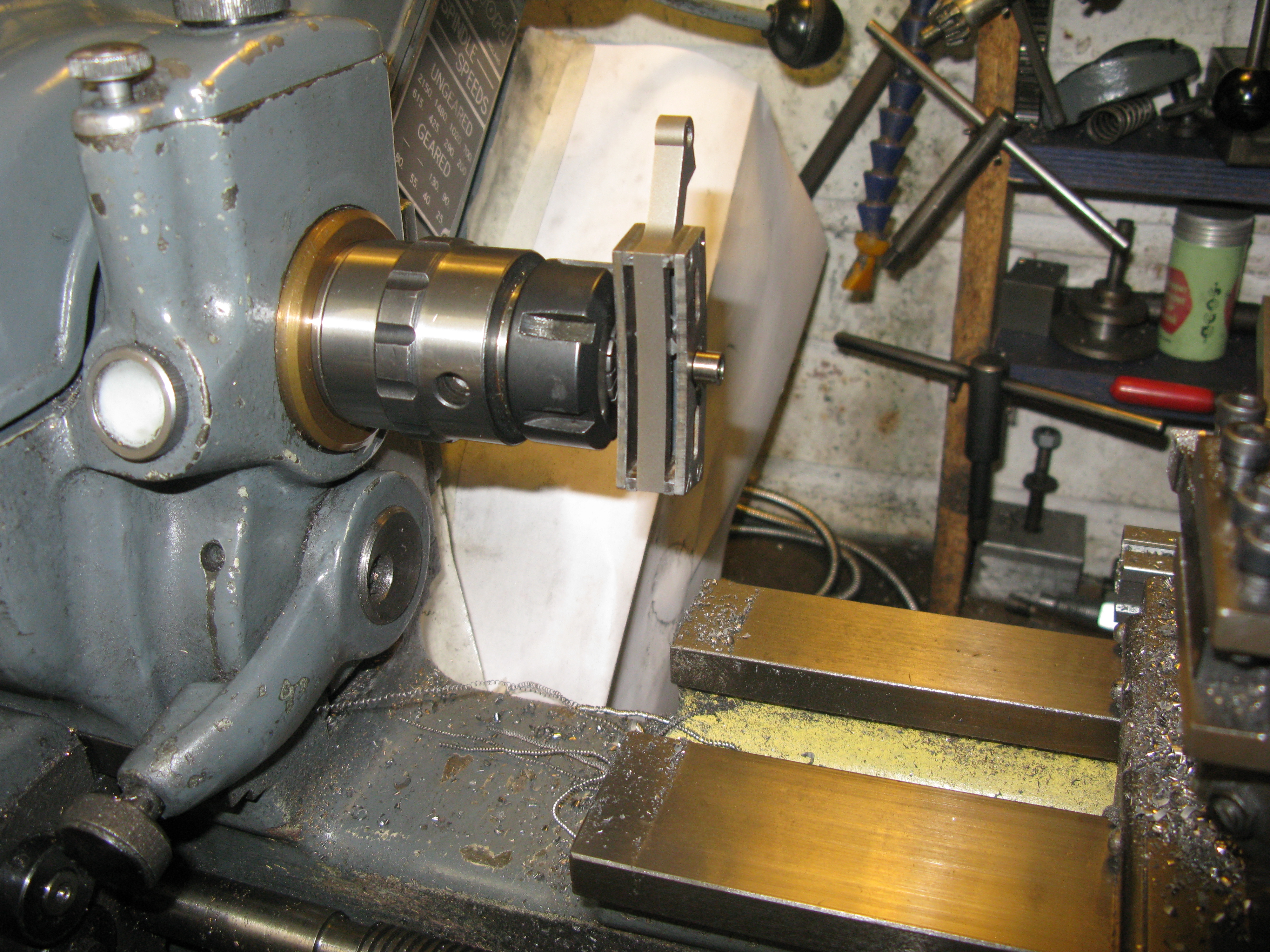
Combination lever
The outside combination lever is more complicated than the inside cylinder as it has to be offset to clear the slide bars. It is machined from 1/2″ square MS bar and the first operation is to do the profile along its length.

CNC machining the combination lever profile
Although the lever is just under 3″ long it still took nearly 3 hours of machine time to cut the profile. Why? well the small mill does not like heavy cuts so 0.020″ at a time at 1 1/2″ feed rate with a 3/16″ slot drill. The holes in the profile are pilot holes which will be drilled and reamed to the correct size later.

Having got the profiled lever the next task is to machine the offset. This was done manually with the lever set up on the mill table against a fence.

Machining the top of the lever.
The lever top was machined first to achieve th correct thickness and length of the set. This was followed by reversing the lever in a similar machining configuration to do the bottom set.
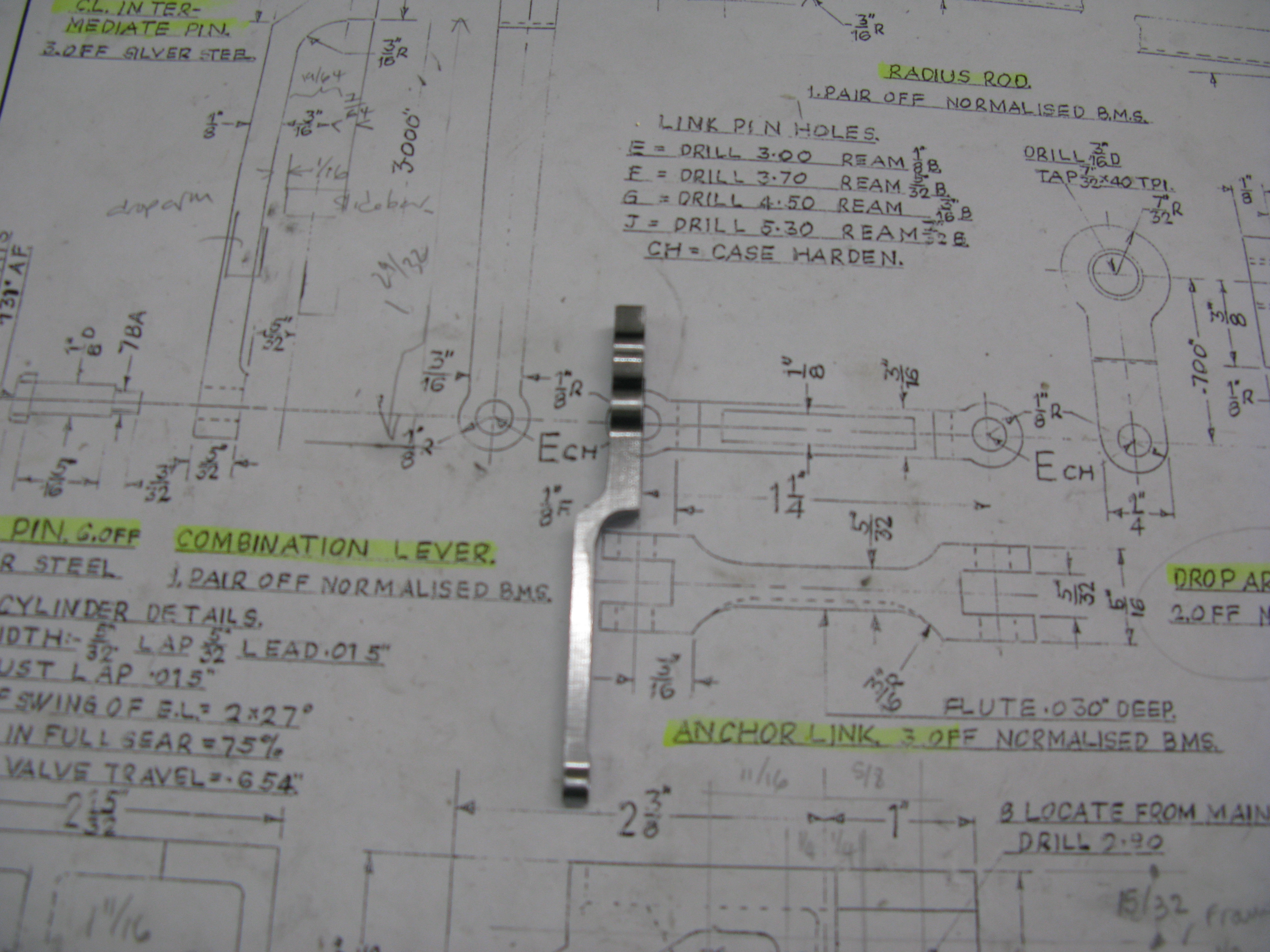
The machined lever in its final form
The holes were then all drilled and reamed to their respective sizes.
The lever can now be test assembled on the valve. Oh no ……. it doesn’t fit. It fouls the bottom of the valve slide block and the top of the slide bars. The answer was to reduce the thickness of the offset top and bottom which fortunately had sufficient material to do this, resulting in the the final lever as shown above.

As can be seen above there is very little clearance but sufficient for the lever to swing. Of course the final test will be when all the motion is complete.
Just another one to make…….. …….and a day later done.
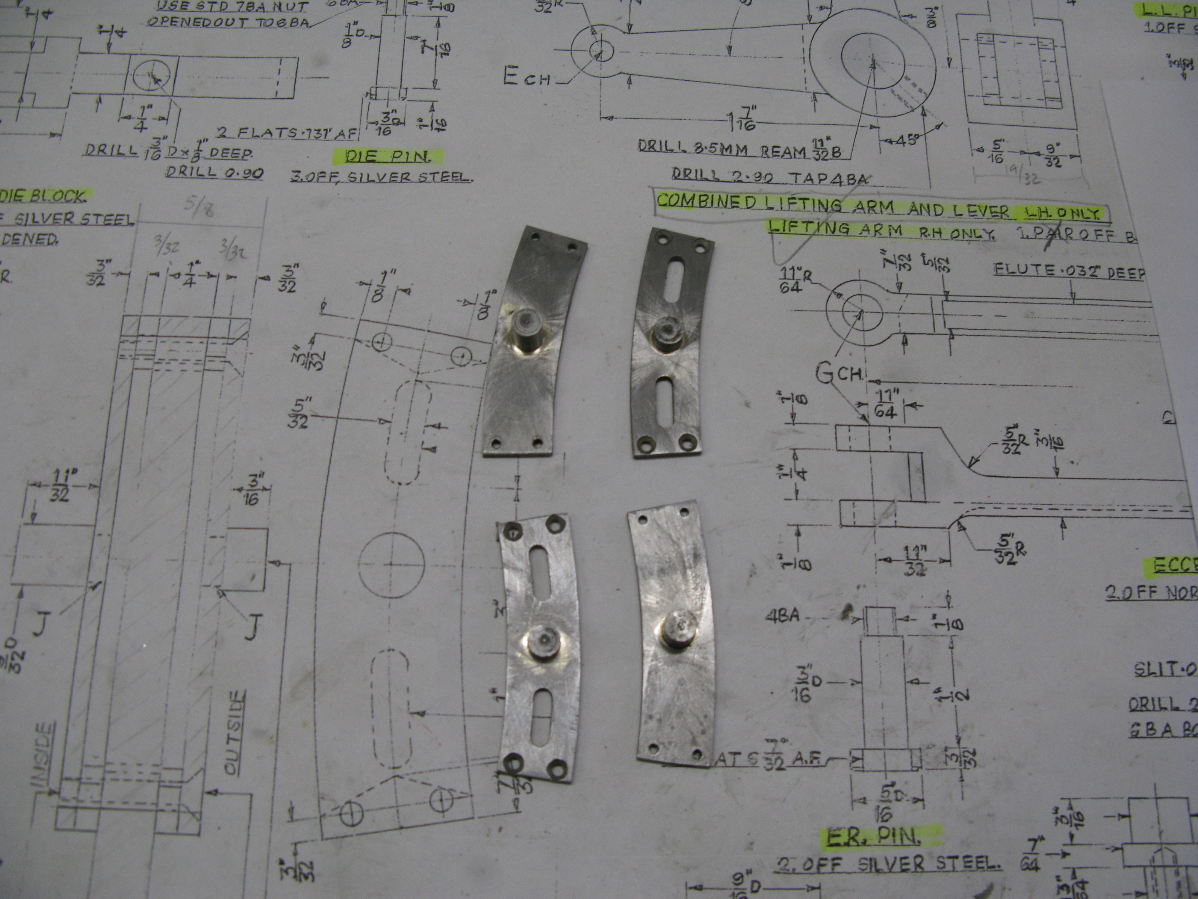
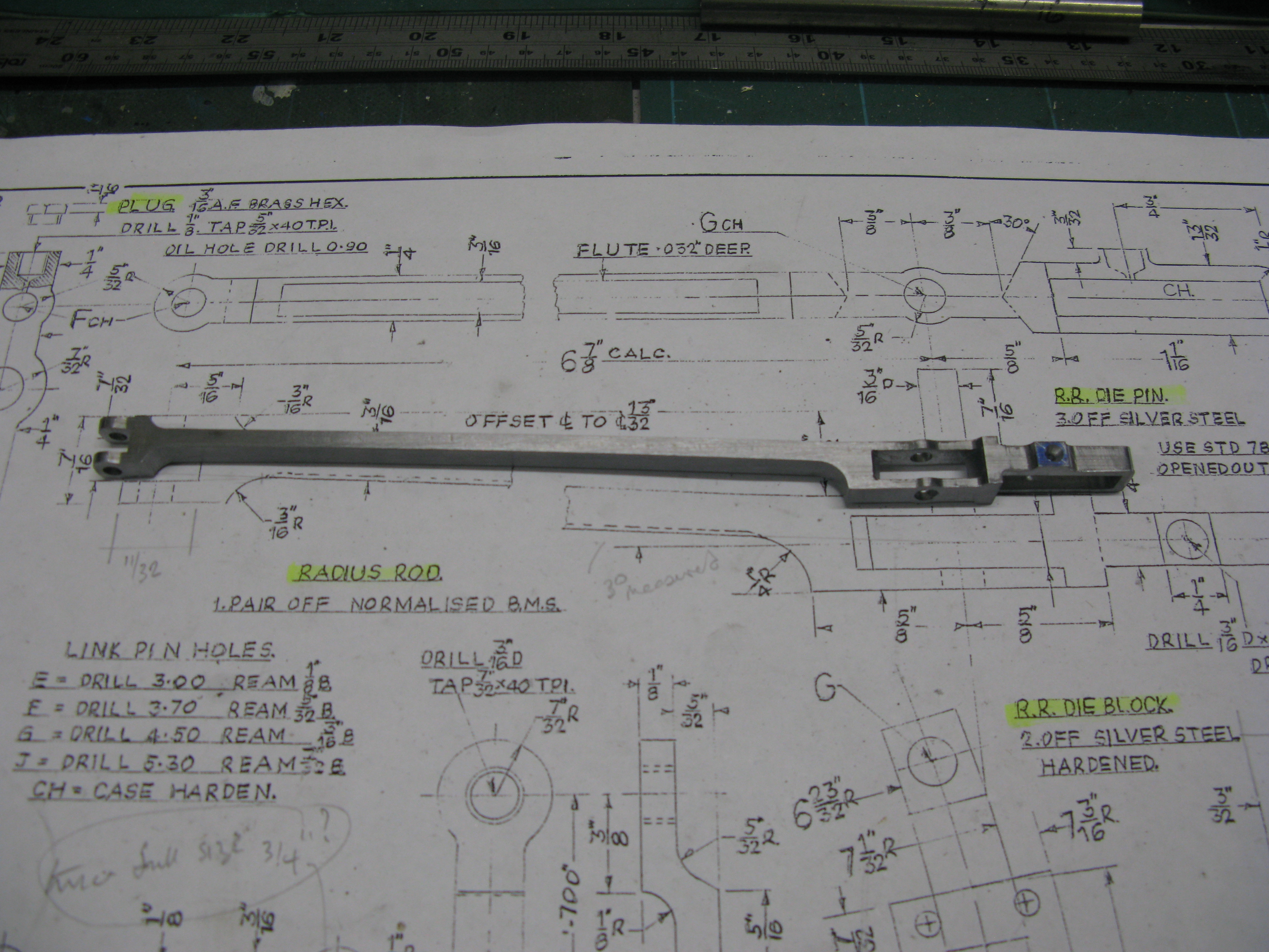
Radius rod
I spent some time deciding how to machine this component because it has an angled offset. It could have been machined straight and then bent but somehow that did not seem the right thing to do apart from having to work out the straight length to account for the offset. The next decision was which profile to machine first, the plan profile which has the offset or the side (elevation) profile which does not but would have to be almost an 1″ in depth to allow the offset to be subsequently machined. In the end I decided to do the elevation profile first.
Profiling was done on the CNC mill and this tested it to its limits I think as the side profile took 9 hours to cut including four planned tool changes and two unplanned to resharpen the tool.

The start of machining the side profile
The first task was to drill a pilot hole for each of the two connections, the expansion link die block and the combination lever. Then the slot for the lifting lever die block and finally the side profile.

The finished side profile
As the rod fits into an 1″ x 1/2″ bar stock it leaves me with a nice edge along the bottom to hold the rod whilst the plan (or offset) profile is machined.
The offset arrangement can be seen in the drawing above the part machined bar.
Machining the plan profile was all going fine until the last 20 thou cut that would release part of the rod from the stock material. As the cutter progressed along the front edge towards the forked end the stresses in the bar caused the material behind the cutter to start to bend away and the whole bar bending, fortunately the bending was away from the rod as the cutter moved back towards the back of the rod. Fearfull that if I allowed the cutter to continue and mar the job I stopped the process and took the work off the machine and used the band saw to cut the rod off the stock material and then hand filed the rod to finish dimensions.
As the rod was cut at an angle across the bar stock the rod itself did not bend from the stresses …phew, that was a relief!
Having learnt that lesson I have stressed relieved the other bar stock from which the second rod will be machined by heating to a dull red and letting it cool naturally. Hopefully it will machine OK.
The rod has had its slots hand filed to give square ends for the lifting lever and angled ends for the expansion link die. The slot for the fork end into which the combination lever fits was machined with a slitting saw.

cutting the plan profile
The completed rod
Having completed the rod machining the next job was to check it fitted with the lifting lever and expansion link.
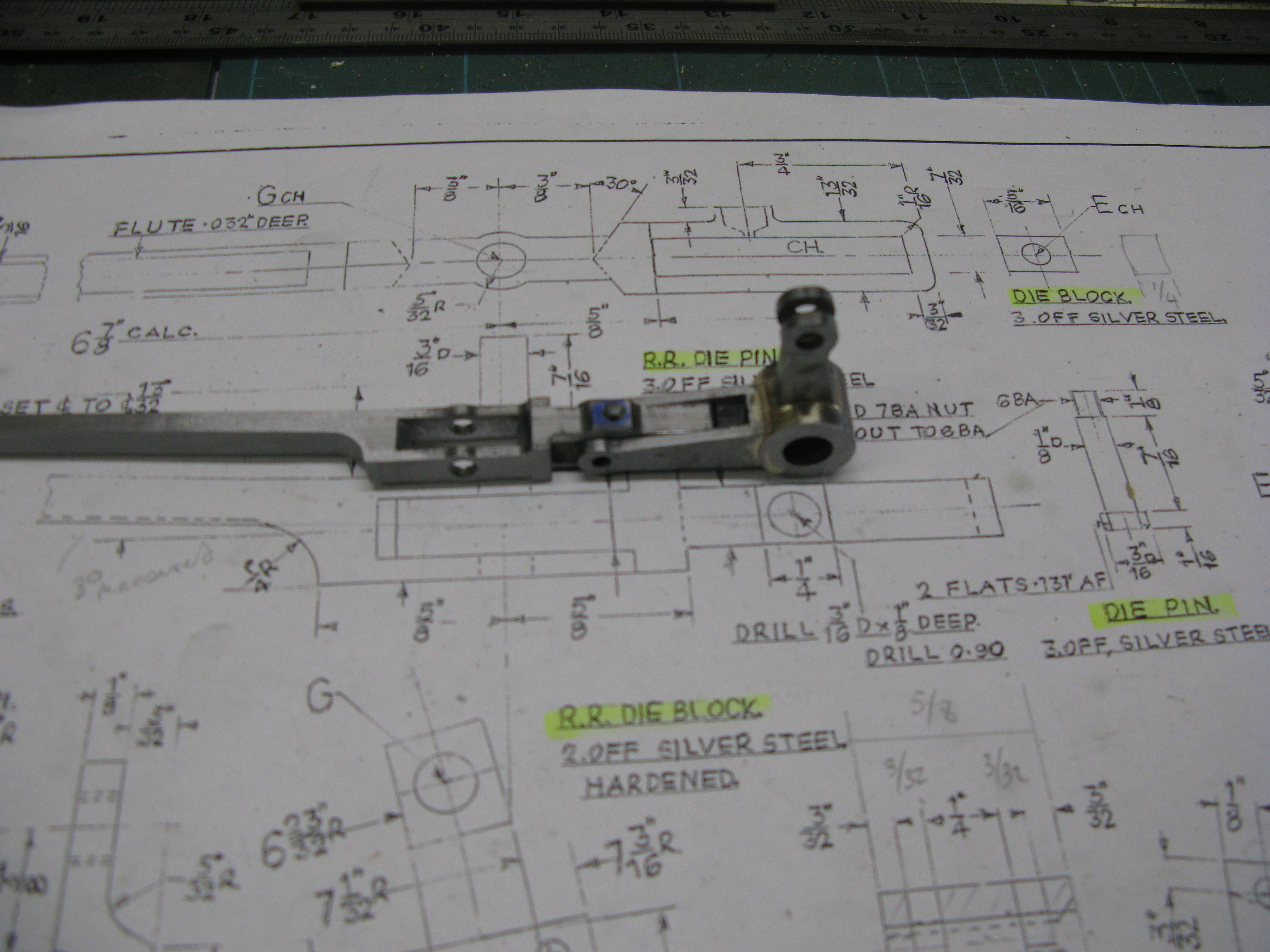
Checking the fit between lifting lever and radius rod

Both rod and lever need some hand filing to get a free and easy fit due to the lifting lever gap being slightly under size and the rod slightly oversize.
The fit of the rod into the expansion link showed that whilst it moved up and down it was a little too stiff for my liking so again a bit of hand filing to get that easy slide fit.

All three compnents checked for fit
More on the expansion link
The wire cut expansion links have been received and the finish is super. Unfortunately I did not get the die blocks cut at the same time (thoughtfulness) and my after thought was too late to get them done by the company who kindly cut the links. So I resorted to cutting them out of silver steel on the cnc mill. They needed a very small amount of hand finishing to get them to fit snugly in the link but free enough to slide. They will be hardened.

The expansion links assembled
The die block is silver steel and it was machined from round bar as can been seen in the photo below.

Being very small in comparison to the expansion link the amount of radius being machine is tiny. The CNC machined product was slightly oversize and with the die block still on its stock round material is was carefully hand filed to get a sliding fit. Much patience and engineers blue (well the equivelent maker pen) to find the high spots followed. The convex radius was easil tackled but the concave radius was more difficult and the swiss file was being used more as a scraper than a file. Once a sliding git was achieved it was parted off from the stock material and then carefull filed to clean up and fit the 1/4″ depth of the expansion link.

The fitted die block.
Just needs to be hardened now, but that will wait until the second one is done and both can be put into the oven at the same time.
Back to the lifting lever, Radius rod and its die block which was made from BMS (to be case hardened). As its just a hole with a rectangle around it the CNC did the job OK and it only required a small amount of cleaning up for it to fit into its slot. Likewise the ends of the slot needed cleaning up with a safe edge square file to get the block to slide fully to each end.
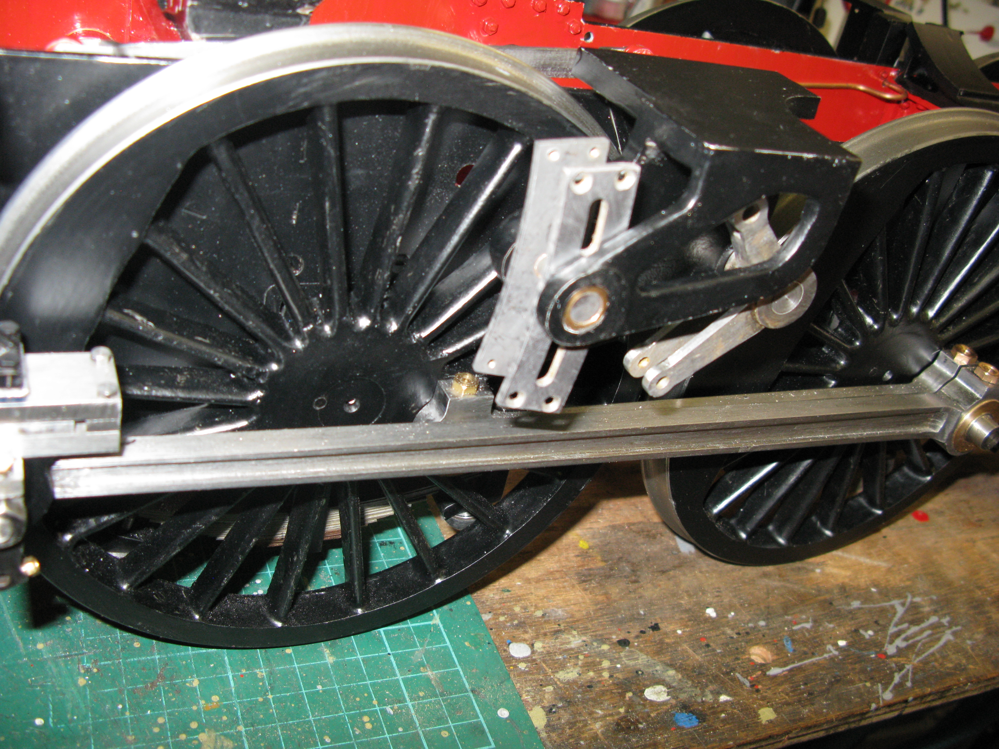
The pins for the fork end of the radius rod and the die block were simple turning jobs which, when made allowed the whole assembly to be trial fitted on the chassis.
That turned out to be quite a challenge as there are so many fitting points on all the parts that have to line up correctly to allow the exapansion link to slide up and down easily when operated by the lifting lever. As might be assumed from this comment mine did not slide up and down easily but was quite stiff. The stiffeness was not down to any one item but a combination of all of them. The offset connection to the combination lever was not perfect which caused the radius rod to twist which in turn caused rubbing on the expansion link outside plates by the radius rod. The lifting arm was not perfectly square on its boss which again caused the radius rod to tend to twist.
Now these alignment issues were not at all significant as individual items but became significant when all were put together. So by dint of seeing where all the rubbing marks occured and by putting a mild amount of extra set into the offset remedial action produced improvement…….but it was a long day of trial and error, dismantling a reassembly many times to get a free moving exansion lever by the lifting arm.

The assembled radius rod and expansion link
Ooops …. forgot to put the flute in. It will have to be dismantled to machine the flute.
The second radius rod has been machined and unlike the first it did not suffer from any stress relieving problems when coming to the end of the cut so the stress relieving of the stock bar did its job.

Machining the flute in the radius rod
The second rod did have its flute cut …… so trial assembly with all the bits was done off the loco and it all went together OK. However when assembling on the loco all was not well. Without the expansion link side plate in position the rod lined up OK between lifting lever and combination lever. But with the side plates in the expansion link would not slide inbetween them. The bracket had to be filed as the first one to remove the paint and provide a bit more clearance but there was still a problem. It turned out to be the side plates not being parallel. A test bar through the bearings of both plates showed the bearings to be lined up OK so the problem was down to one or other of the trunnions on the side plates. Checking the side plates by putting the plate in a tailstock chuck and bringing up to a face plate showed that indeed one of the plates had its trunnion not square with the plate. The plate in question was the outside plate with the short trunnion.
My intended solution to this was to mount the plate on the face plate and turn down the existing trunnion and then sleeve it back up to the correct size……… a job waiting to be done.
Having had a few sleeps I decided the face plate approach was not a good one, as aligning it to run true was going to be problematical. The solution I did adopt was to run the complete expansion link assembly in a collet. That way I could ensure the trunnion to be corrected would run true with its opposite number when machined down and sleeved.
The sleeved corrected trunnion
Having successfully done that I decided to check the other one and that turned out to be slightly out of true also so It was treated to the same corrective action.
With both sides now with their expansion links in place I could line up all three expansion links on the centre line of their trunnions and pin the lifting levers onto the shaft. This proved problematical as I found the silver steel bosses had becom hard from the silver soldering process of putting the arms on and I could not drill all the way through the bosses. Fortunately the hard spots were adjacent to the arms so I could pin through one side and into the shaft.
Now all three expansion links could be operated together I found the movement somewhat stiff. To be investigated.
Following dismantling both expansion links there were no obvious friction points but the centre cylinder was not dismantled so there may be some tightness there. I will now wait until I have the crank rod and crank arm in place to hold the expansion link firm before doing any more checks.
In operating the expansion links I found the fork end of the radius rod fouled on the combination lever as the fork was not deep enough although machined as drawn. I therefore had to modify the fork end by filing an angled bottom to the fork from both sides creating an inverted V at the bottom of the fork to provide the necessary clearance.
The next job was the union links. Again my trusted CNC cut the profile and then the reliefs were machined on the mill.
Machining the reliefs on the union link
This was followed by cutting the flute and then the fork ends were cut using a 3/32″ slitting saw and a couple of passes.
A completed union link
With the union links in place I have to check a full revolution of both side wheel sets to ensure no fouls occur in the link webs ….. a job to be done……….
In the mean time the return crank can be made. This is machined from bright EN3B bar with a silver steel crank pin.
The profile, as is my usual way, was machined on the little CNC mill.
A pair of return cranks profiled.
Following the profiling the two holes were drilled using the pilot holes to centre the work under the quill of the mill. The work being being clamped to the mill table on a piece of sacrificial material.
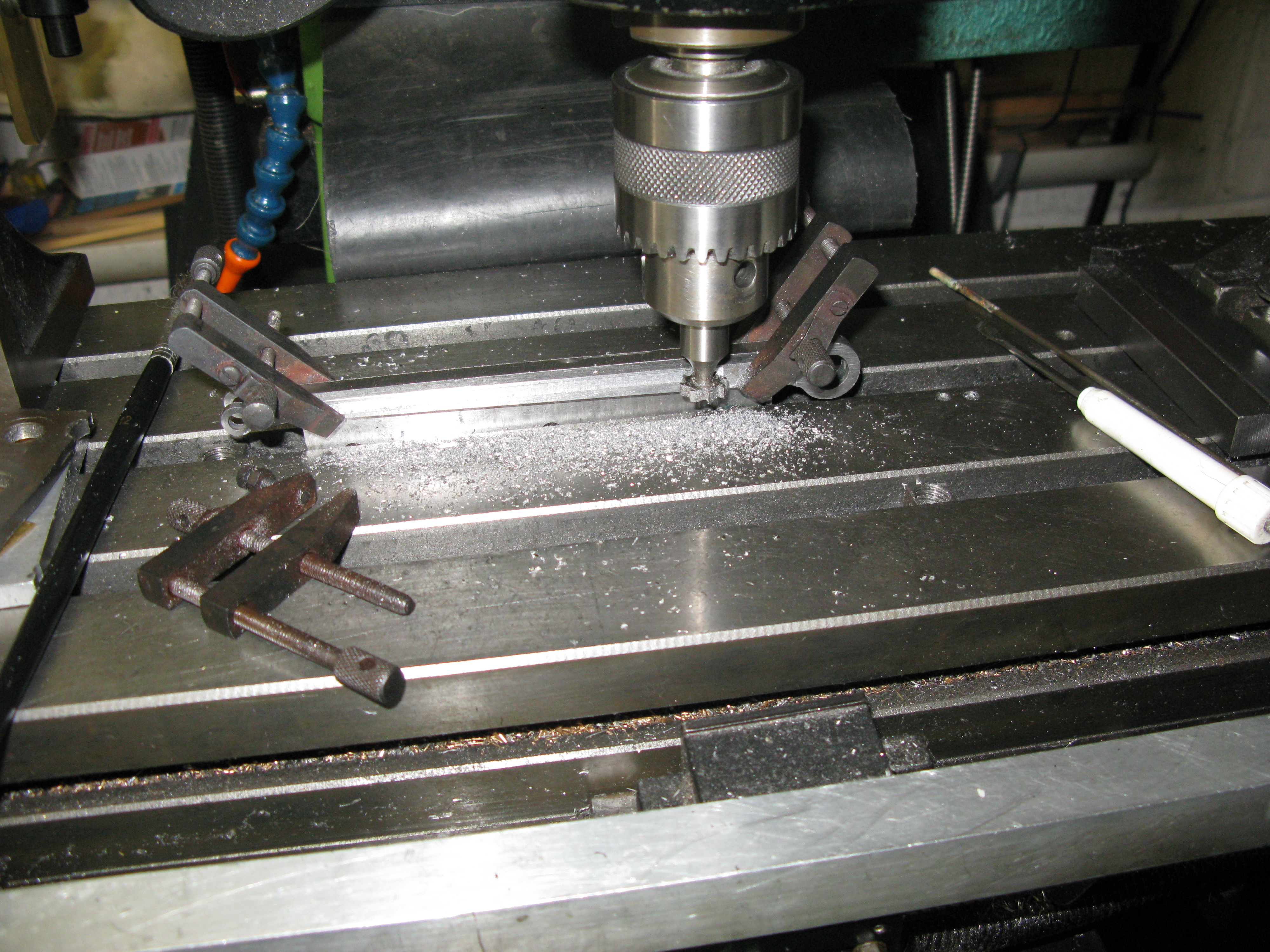
Next the hole for the clamping boilt was drilled and then the 0.020″ slit put in to allow the clamp bolt to tighten the return crank onto the wheel pin.

Putting the slit into the return crank …… its the only saw I had but the coarse teeth were no problem
The return crank pin was machined in a collet on the lathe. It has a 2BA tapped hole on the outside to accept the return crank retaining cap and the pin is drawn as a press fit into the crank. As the crank is only 3/16″ wide I chose to use a slide fit with a retaining compound (Loctite) and then pin with a 1/16″ pin for security.

A return crank fitted but not yet correctly aligned with respect to the drive pin.
The return crank has to be aligned so the pin pitch circle diameter is 0.878″ according to the drawing. I now have to work out a way to set it up as there is no obvious access to either the drive pin or axle centres which are the two obvious reference points.
Having had a sleep I tried a method as described below.
First I drew out the relationship of the return crank to the wheel drive pin.
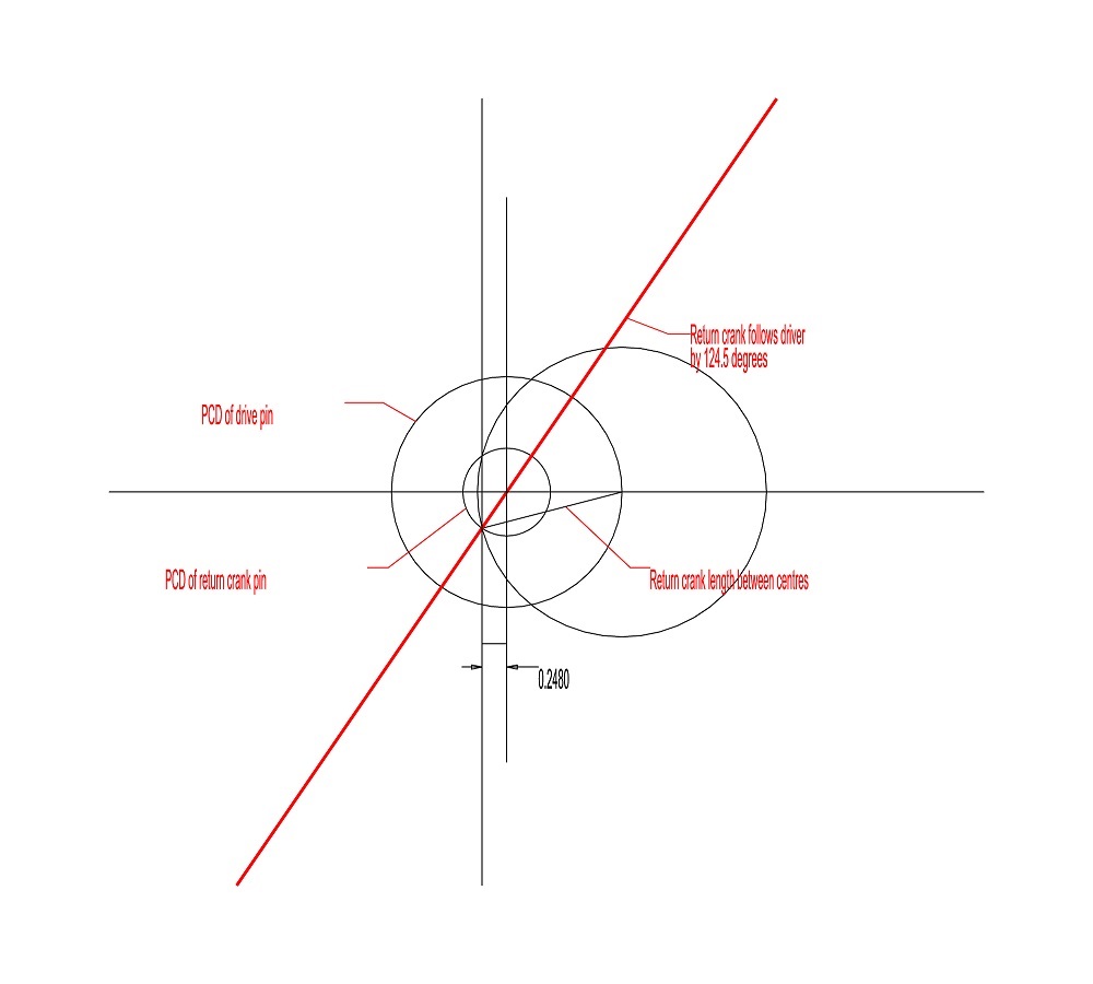
This was a bit of a surprise at it turns out the return crank follows the drive pin by 124.5 degrees. I would have guessed at somewhere around 90 degrees. Anyway the important measurement I needed was the distance bewtween the axle centre and the return crank pin with the wheel driver pin at back dead centre.
I clamped a rule across the outside of the driver wheel so one edge was on the centre line of the axle as near as I could tell by observing the centre drill depression on the axle end. I then clamped a small square to the connecting rod so that its edge was 1/4″ away from the rule edge.

Then using a larger square so its edge was contacting the small square the return crank pin was moved so its centre line coincided with the edge of the large square and the clamping bolt tightened.
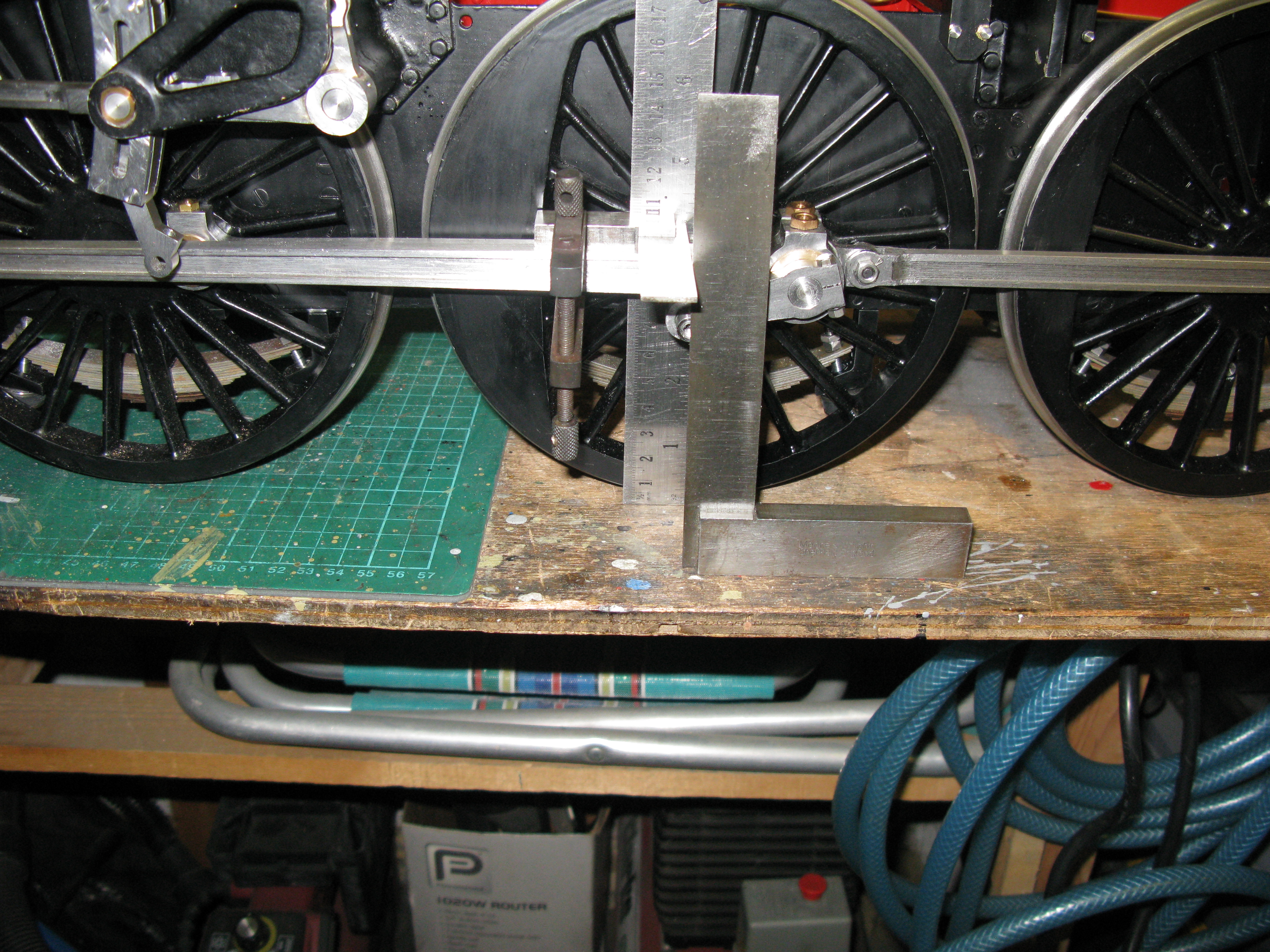
setting the centre of the return crank pin.
Now all this was done as can be seen on the bench so I will not claim it to be absolutely accurate as a method but I do not know how the inaccuracies (if any) will translate into the piston valve movement in relation to the the piston position. I will only find that out when I attempt to set the valves.
Having set the return crank my mind turned to the making of the expansion link rod that connects it to the expansion link. The drawing provides a measurement between the fork end and pin end of 6 17/64″ and then helpfully (!) adds “approximately, check from job”
So now another dilemma how to verify the correct length of this rod as the expansion link is not in any fixed position.
Perhaps another sleep will bring a solution.
Which it did not, but it did make me realise I had made an error in setting the return crank as I had read the drawing as it having an PCD of 0.878″ when in fact it was a pitch circle radius! So that explains why I was surprised at the angle it was set at. Redrawing the setting it can be seen that the return crank is indeed at 90 degrees.

So both cranks have to be reset by using the same set up as before but not offset by 1/4″.
Now I can return to the return crank length issue.
I decided that I would make a temporary rod with the pin in one end in a slot so it could be adjusted with the slot centred around the as drawn dimension. With the temporary rod fitted and the driver wheel on back dead centre (or front dead centre) the radius rod should be able to move up and down without any movement of the radius rod forward or backward.

Tempory return crank rod
However in addition, in an ideal world the steam cut off in the cylinder should be the same on both the front and back stroke of the piston. To find out this I used a piece of software known as Dockstader writen by Charles Dockstader in 1986 as a DOS program but eventually upgraded to work with Windows in 1999/20000. It is freely available on the web.
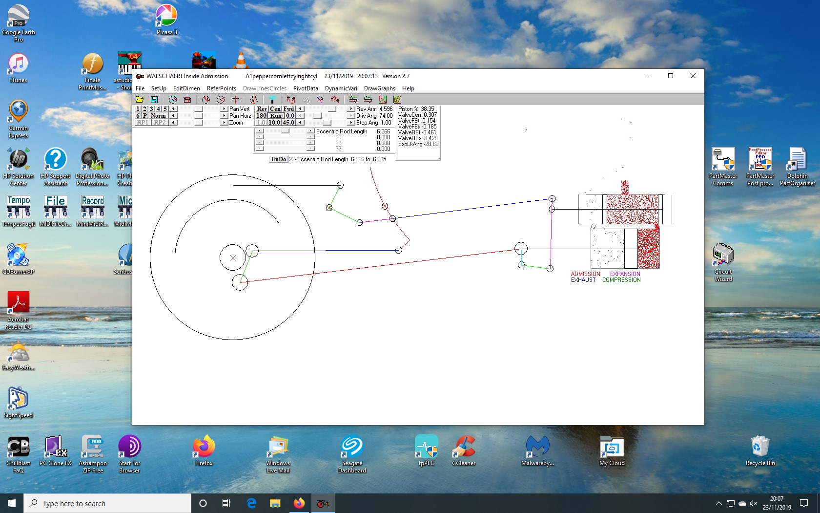
The Dockstader animated software. I cannot blog a video as my plan only allows photo’s.
To use the program a lot of measurement data has to be inserted associated with the motion and cylinder and I found quite surprisingly that a few thou difference can make a noticeable change to the results.
By playing around with the return crank rod length I found that just about equal cut offs could be achieved for each cylinder and the rod length turned out to be 6 1/8″ some 9/64″ shorter than the as drawn length, the cut off being 70.2% and 70.5%. This somewhat unusual as normally the angularity of the rod means that unequal cut offs are the norm.
If the rod was made longer higher cut offs could be achieved but they became unequal by 10% or more. So I have to decide if to go for higher unequal cut offs and the rod length nearer to that as drawn or significantly reduce the rod length and get equal cut offs. The Jury is presently out.
Out of interest I did a rough plot of how the cut off varied with the change in rod length and position of the reversing arm.

The result is above with the dark line with 1/2″ linear horizontal movement of the reversing arm pin and the light line with a further 1/10″ added.
As can be expected with more movement of the reversing arm lever the cut off increases, The effect of the change in rod length can also be seen as the longer the rod gets the more divergent is the cut off between the front and rear stroke. The as drawn dimension ( to be checked) is the grey line 2/3rds the way up (6 17/64″ or 6.265″). I chose to go for 6 1/4″ giving a front cut off of 78.1% and rear cut off of 64.8% with the reversing arm movement of 0.6″. It is a purely arbitrary decision.
One thing that did show up irrespective of the return crank rod length was that in mid gear the front steam port was opening slightly. This has nothing to do with the return crank rod and could be for any number of reasons including my dimensions of the cylinder valve ports and rings. Nothing I can really do about it now and its not too serious as it cuts off quite quickly and of course in mid gear the regulator would be closed and no steam entering the valve anyway.
Now all this mental effort has not actually set the valves yet. Once the return crank rod is made and fitted then the valve stem can be screwed into or out of its cross head slide to set the valve position relative to the ports. A job for the future.
The return crank rod was machined from 3/4″ x 1/2″ BMS with its profile done on my CNC X1 mill. It took 4 1/2 hours to machine the profile. Patience is a virtue. Fortunately I could get on with other things whilst regularly checking the job to clear swarf and provide cutting oil.

The return crank profiled.
The holes for the PB bush at the drive and and the 3/16″ pin at the other end were drilled out and reamed to size, leaving the next task to mill the reliefs on either side.

Milling the relief on the inner side
Finish milling the drive boss end as the chuck interfered with the clamp on the first set up
The rod was turned over to do the other side relief in the same manner which was only 1/16″ deep compared to the inner side which was 1/4″ deep to achieve the web offset at the expansion link end.
With the reliefs done the web needed to be cut out and to do that I used the next set up as illustrated as the rod being tapered cannot be held in the machine vice to use a slitting saw so it was slot milled in the vertical poition.

Finally the flute has to be put in.
To do this I set a fence with its top parallel to the mill table and then clamped the rod to the fence so its edge was flush with the top of the fence. This enable the tapered flute on one edge to be done at a fixed distance from the edge (1/32″).
Milling the flute
However I could only clamp the rod to the fence in the manner shown which precluded the flute being machined right to the ends. To overcome this I used a third clamp which was put on behind the tool once the tool had reached the end clamp and the end clamp then removed. This had to be done at both ends. Having done the one edge the rod was turned over top to bottom so the second edge could be machined in the same way.
Finally the return crank boss and the pin for the web were turned and a completed rod fitted.

Just got the other side to do now……..
……..which is now done, so all the motion work is complete and I can start to think about setting the valve timings.
