I have spent quite a few hours looking at the drawings attempting to understand the running boards and their construction. The drawings are not the easiest to follow when you are unfamiliar with way they are all supported and fixed to various places.
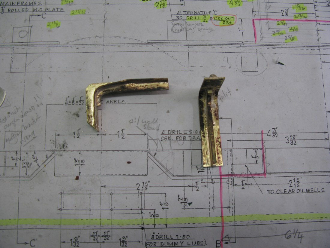
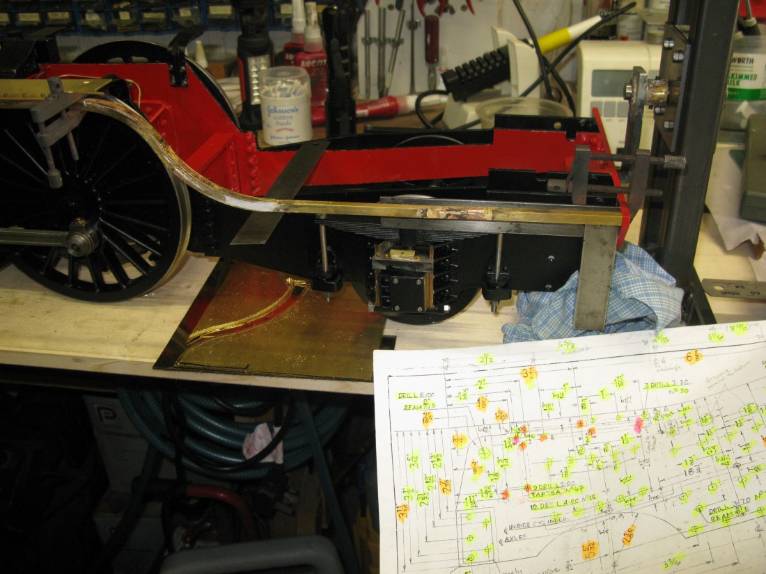
Making a start from the front of the loco the front plate goes right across the buffer beam and then extends on the outside of the frames a couple of inches or so towards the rear, but on the inside of the frames it is flat and then bends up at an angle and the cylinder valve spindle cover pokes though it. There are brass angle pieces 1/4″ x 1/4″ that bolt to the inside of the frames to support the angled front and further angle along the top of the frame back to the cylinder to support a flat plate under the smoke box door. These angle parts are bolted to the frame from the inside using 7 BA set screws. They have to be round head as it is nigh on impossible to get a hex head set screw in the space available let alone a spanner to tighten them and they will only have 1/8″ of thread i.e. the frame thickness to screw into.
This plate I decide was going to be made in two pieces as I did not fancy my chances of getting the bent inner part at the right angle and the hole in the right place for the cylinder valve spindle, so a split line was decided through the centre line of the hole. The idea was that once the bottom part was made to fit the top part would be made to fit and the two parts silver soldered together.
The two pieces of angle supporting the angled part of the plate were straight forward to make and fit and the three pieces of angle to support the top plate were silver soldered together and fitted so that when the plate sits on top it is flush with the frames.
Interestingly the full size has half the cylinder end cover extending through the plate not just the valve guide bit. Not sure why the drawings are different but this is just another anomoly between the as drawn model and the full size.
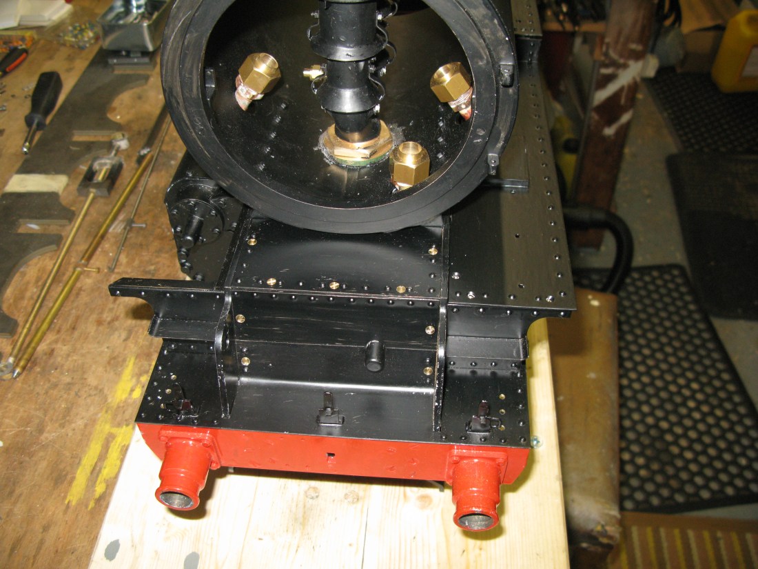
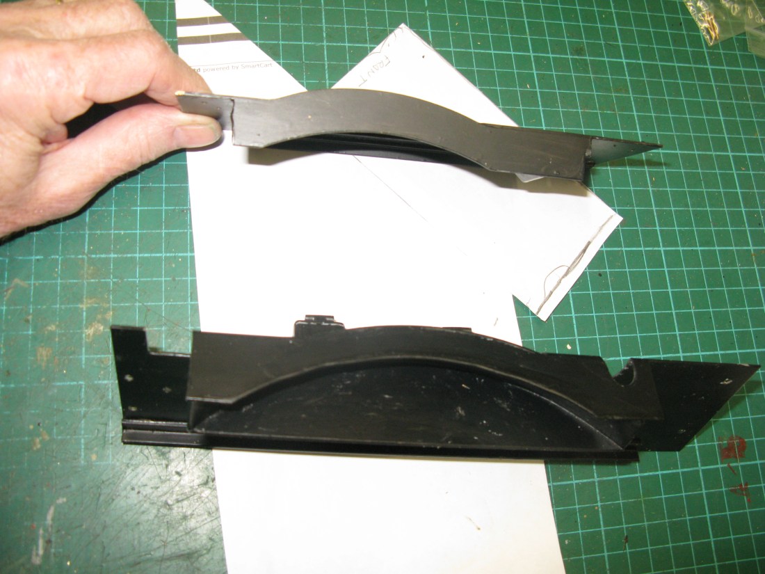
Suprisingly there is quite a lot of work around this front end. The running board end plate has a step on it which is not shown on the drawing and of course there are the lamp irons as well, again none are drawn, so I have done the best I can from looking at photo’s of the full size.

End plate showing the step and rivets
Also there are rivets on the end plate on front plate so I just put in 1/16″ rivets for show as the angle is soft soldered to the plate.
The three bright c/s screws above the angle are holding the smokebox saddle in place. They were bolts but the heads fouled the angle so the bolts had to be replaced with the c/s version as seen.
The lamp irons accomodate two lamps each. The top lamp is the traditional oil lamp but below this is fitted an electric lamp. I will do these much later. There is a small handle to added to the outside irons which is there to assist someone to climb the front running board steps. There are some rivets to be added to the plate as well.
Having spent still more time perusing the drawing and comparing it with full size photos I have found another problem. The running boards slope down to the frame top where there are wheel splashers and two of the running board brackets have the slope for this to occur. However the motion bracket does not have the slope. It’s not drawn on the motion bracket drawing and the casting does not come with one either. So whilst the as drawn running boards have the slope drawn, it is not possible to do. Even if I dismantled all the motion, the bracket is not designed so as to enable a slope to be machined on it without weakening it.
So, I have concluded that my running boards will have to be totally flat along the whole length and width. A big deviance from my prototype. Not happy.
Whilst looking at old A1 photos and the more recent new build Tornado I realised that there are a number of smallish oil resevoirs that have to be accomodated on the running boards. These are going to be all functional on the model as there is quite a few moving parts inside the frames that need regular oiling. So as well as other non drawn items these have got to be designed and mountings made for them.
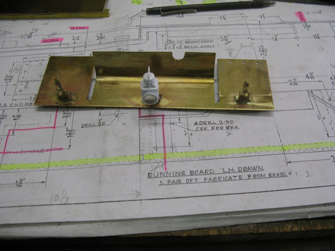
There is one large oil resevoir on the front side running board and I have added a mounting plate with two 8 BA screws soldered in to accommodate the resevoir when designed and fitted. On the full size this resevoir seems to have 6 or 8 exits but I think I will have much less on mine due to the practical size of the small pipes and accommodating their fittings.

Front running board with upstand for oil resevoir (with etch primer)
The raised protion of the running board above was made by using 1/4″ x 1/4″ x 1/16″ brass angle soldered to the bottom plate and then machined down to the correct height.
The top plate was then soft soldered in place.

Plus a line of 1/16″ rivets which are dummy in that they do not hold the angle underneath the plate in position, it is soft soldered on. The number of rivets was ascertained by counting from the Tornado photos.
The three holes at the front are for a piece of angle which is bolted in position and will form the fixing for the smoke deflector. There are fixing holes yet to be drilled in the photo above to fix the plate at the front onto angle which is bolted to the frame and at the rear there is an upstand still to be added as can be seen in the photo further up.
Well the front boards are now all complete. In the end I decided to keep the split front board rather than silver solder the two halves together. It makes assembly easier. Screw heads have yet to be painted. (Not sure why there is streaking in the photo on the top centre plate, seems OK in the flesh).

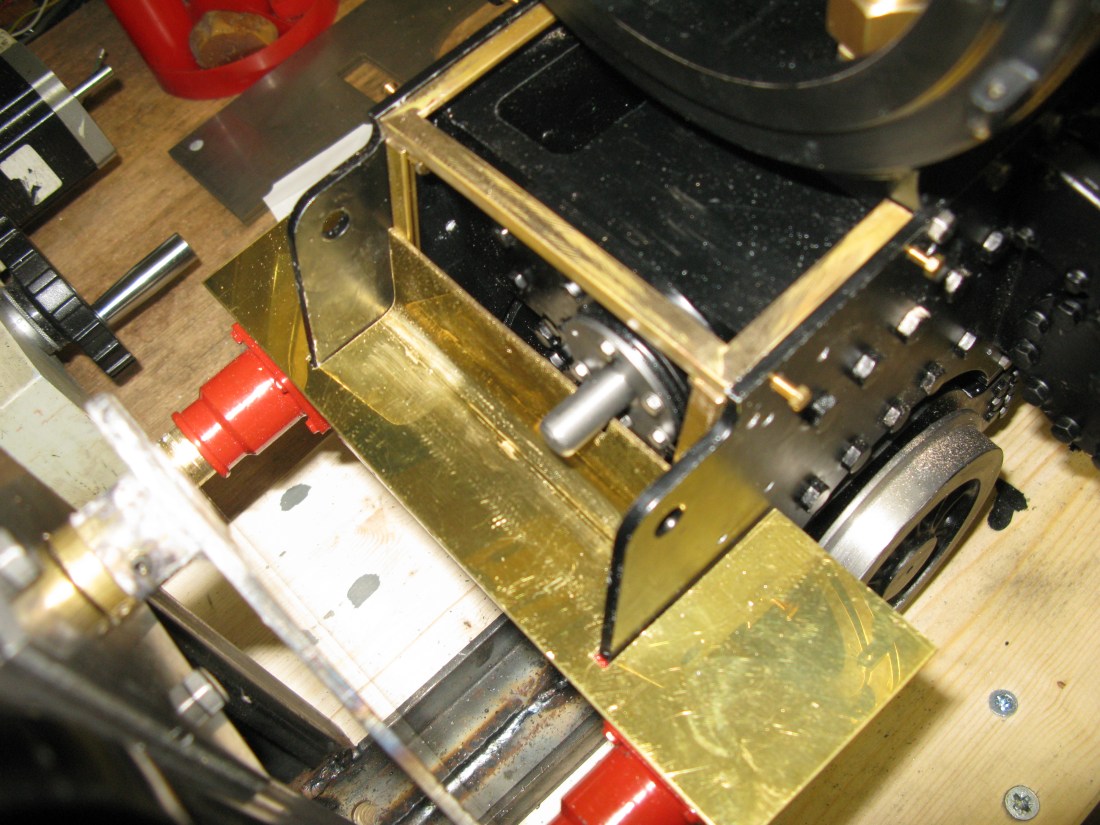
Some progress on the running boards (right hand side only). The splashers protude under the boards to cover the wheel tops front and back. The board currently in progress (the unpainted one) has to have the two dummy sand box fillers put on and a couple of oiling resevoirs. The dummy ssand box filler fitted in front of the splasher aslo doubles and a lubricating tank oil filler. However the 1/2″ pipe from the dummy top has to go down the side of the boiler and it should go down the part of the running board that is sloping inbetween the splashers. However because of the motion bracket being the wrong design the sloping part of the running board cannot be done and my running boards have to be flat across the whole width. This means that there is inadequate space for the pipe between the boiler and running board. I think I can overcome this problem by having a notch in the running board for the pipe to locate in.
Another problem I came across when marking out the running board for the dummy sand box fillers was I suspected that the rear filler was going to foul the boiler cladding as it is locted at a pont where the boiler has a larger diameter. To check my suspicions I put the boiler in the frames and sure enough the foul existed.

The black outlines are where the dummy sand box filler should attach to the running board. The front one is OK but the rear one is not. Still thinking how to overcome this foul.
After a sleep I have decided to leave the problem for now. I cannot really solve it until the boiler cladding is in place so this bit of the running board will have to wait to be finished.
Now the next problem. The running board from the point in the picture above goes past the wheel and then descends in a reverse curve to the drag beam. That is quite a length. It is also quite slim as it passes the boiler fire box side. There is no way this length of running board is going to successfully support itself securely over this length. Looking at the full size Tornado prototype there are two brackets missing from the drawings. One just in front of the fire box and one under the ashpan just before the cartazzi axle spring hanger. So these are now going to have to be designed and built and somehow back fitted onto the frames which means drilling in situe…….ok well…..
The new brackets have been made.
They have turned out to be quite solid with the 1/8″ thick web and 16g brass. The design is taken from the full size Tornado which had a very useful picture of one mounted on the frame.
The drilling and tapping of four 7 BA fixings for each bracket was difficult having to do it inbetween the frames. I used a Dremmel drill with a right angle drive to drill the holes using the bracket as a jig clamped to the frame. This was tricky and I can’t say I was totally happy with the result as the holes turned out not to be truely vertical. Tapping the holes was a nightmare and having done one bracket the second one was not so succesful and I managed to break a tap in one of the top holes so the bracket ended up with only three fixings. Not a major issue…. just annoying ….. despite it not being visible.
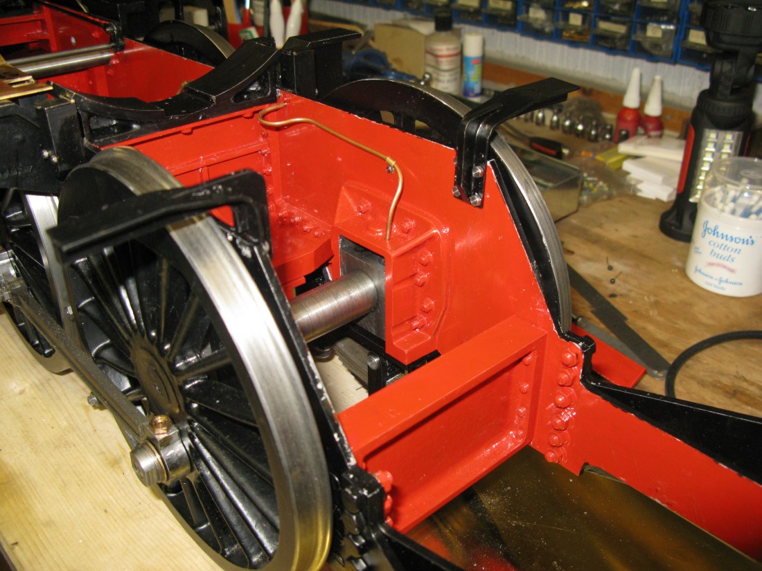
The painted and fitted brackets as seen above have to be double checked that they clear the boiler. Lifting the heavy boiler on and off is proving a bit of a strain as I am wary of doing damage to either the frames or the boiler or both.
As it happened when the boiler was put on there was insufficent clearance for the cladding so the brackets had to come off and have the inside top corners reduced somewhat. Fortunately second time round it turned out OK.
The next pair of brackets will have to wait until I have done the angle support from the buffer beam up to the new brackets fitted as this will determin the height that the new brackets will have to match.
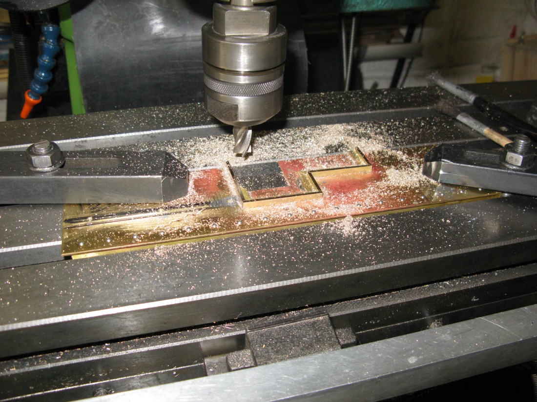
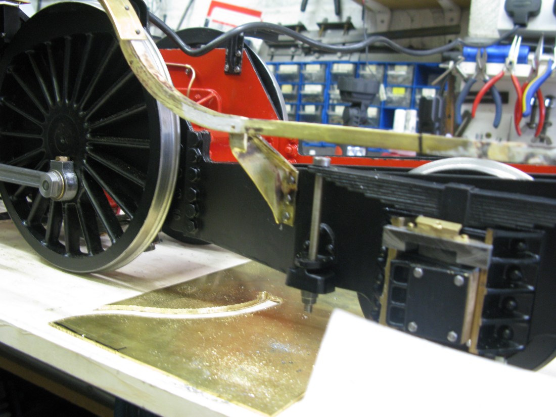
The reverse curve on the running board was not going to be easy. There was no way brass angle was going to bend even with appropriate rollers. I have tried and the brass just cracks or deforms from square. So the bend would have to be fabricated. The vertical part of the bend was cut on my little cnc mill and then a straight length bent to match the profile and the whole silver soldered together.
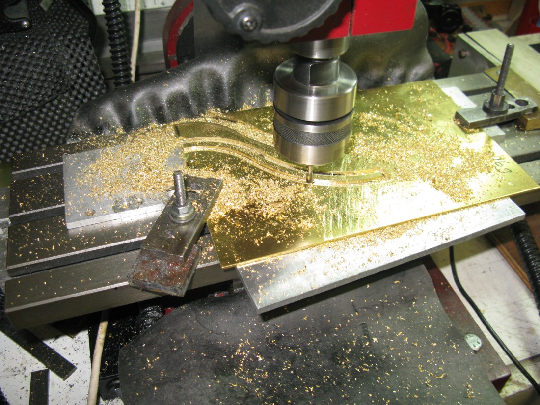
Machining the reverse bend

It was a bit of a juggling act but with the help of numerous clamps I managed to get the two parts successfully joined.

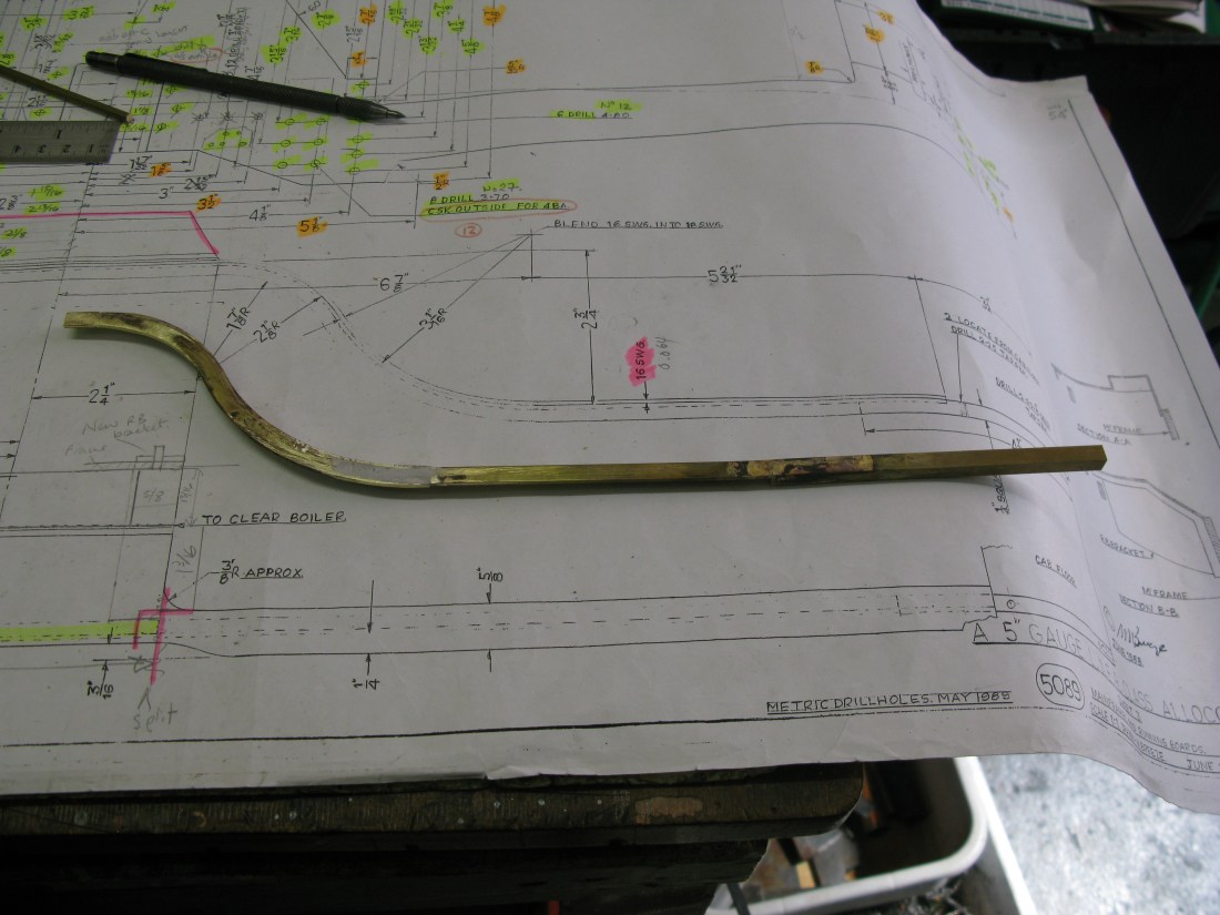
The S bend has to be lengthened so it goes right up to the drag beam but the lats 3 1/2″ or so is actually 1/4″ square brass so the pieces have to be joined. Also to match the running board at the front end a small piece has to be added there also.
The rear end is held in place by a 5 BA c/s screw through the drag beam into the 1/4″ square and the front end rests on the new bracket and to hold it in place there I used a joiner strap on the angle as the running board is not very wide at this point to have a screw into the support bracket.
The square clamped to the drag beam to check the angle is level with the frame
The actual running board that wraps along the angle is in two pieces. The first piece at the front goes around the top curve to about half way down where the transition to the reverse curve starts. The second piece is thicker at 16g and extends as far back to where the cab floor starts. I presume the thicker gauge is specified for extra strength otherwise I can see no reason for it. The joint of the two pieces has to be blended to give a smoothe surface.
The running board immediatley in front of the curved portion cannot be finished as it has a vertical bit to make the wheel splasher that fits up to the boiler cladding. So that is some way off before that can be done.
Next job is to design and make the extra suppport bracket that fits just in front of the spring hanger.
This turned out to be quite time consuming. mainly to get all the angles just right and then to make sure when fitted the distance between the frame and the angle was right.
The baraket was made out of 18g brass sheet and folded to shape. One piece had to be added and silver soldered in place which was the part against which the angle was to be screwed to.

Bracket temporarily fitted with loose screws.
The angle is fixed to the bracket with a 10BA c/s screw.
When it was all tightened up the angle was really solid. So happy with that.
Having done that the running board plate was cut from 16 g brass, rolled, dummy rivets put in and then soft soldered to the angle.

The rivets do not go all the way back but stop in front of the cab.
Well that’s as far as I can go with the running boards for the moment. The other side has to wait until I can turn the engine around on the bench.
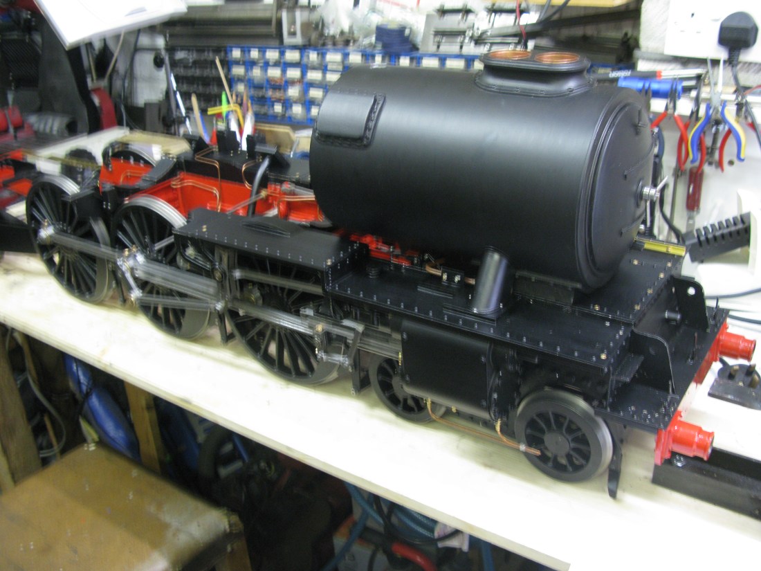
So, the loco has now been turned around on the bench. I was a little concerned about doing it because of its weight but with a bit of care it slid around keeping the heaviest end (the front) on the bench at all times.

The first to running boards have been done. The two oilers have to be made and fitted and also the steam pipe jacket which will be the next task.
(The superheater element in the front is the leaky one as described in the boiler chapter.)
oops slightly out of focus …..
When doing the cladding it became aparent that the running board splashers for the front and middle driver woiuld have to be modified as they would not pass the whell rims. So the rear splasher had to be radiused to allow the running board to slide in over the wheel.
Although perhaps not too clear in the above photo ’cause its painted black, the rear splasher is now radiused.
