Weighshafts and reach rods
A new section for this little lot. As I had finished putting the inside cylinder assembly in the frames I thought I would do the weighshaft and lifting arm and lifting lever for the inside motion to complete the assembly and also hold the expansion link a little more firmly as I worrked the motion to see that the cylinder and valve movements were OK.
The inside motion weighshaft is a simple affair of a 3/8″ dia. rod in a pair of PB bushes mounted in the frames. What the drawing does not tell you is which way round the bushes are mounted in the frame. The bush lip could be outside or inside. Eventually the penny dropped as the length of the weighshaft was 1/32″ less than the outside width of the frames, so the bushes went in from the inside. The weighshaft is held in place by a collar at one end and the lifting lever at the other end.
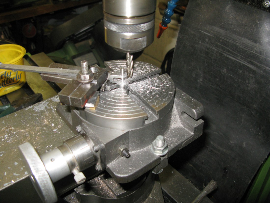
The lifting arm is a separate item and is a slotted bar silver soldered to a 3/4″ diameter bush. The first task was to machine the 1/4″ wide slot in 3/8″ x 5/16″ BMS bar using a slitting saw. In my case a 1/8″ one and doing two passes. The slot was not machined centrally on the bar but offset to obtain the correct thickness of one arm leaving a thicker arm on the otherside. The purpose of this arrangement allowed material to remain when the contour was machined holding the work in place which could be machined away later. Once the slot was in the bar the arm contour could be machined on my X1 CNC mill. The bar was clamped to a sacrificial plate thick arm at the bottom, and a 1/4″ packing piece put in the slot and the 1/8″ hole for the pin drilled first. A 5BA set screw was then used to hold that end down on the sacrificial plate whilst the bar was clamped down at the far end to allow the whole contour to be machined.
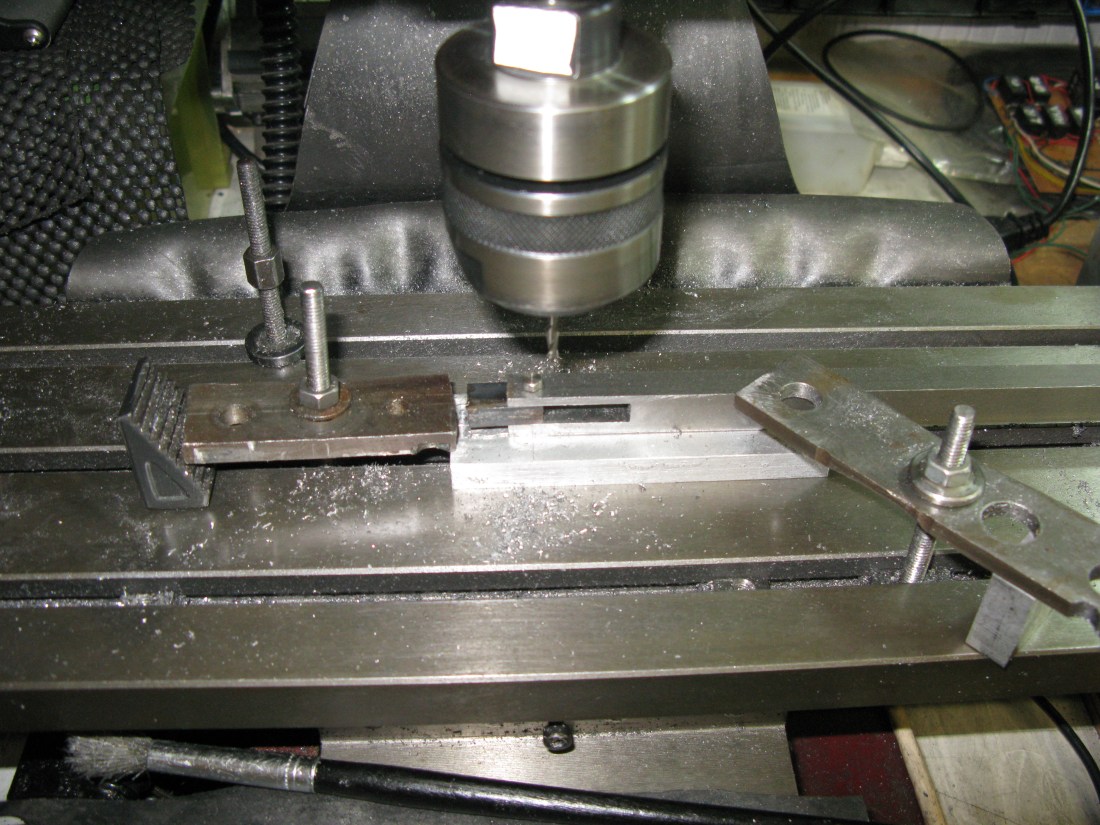
Arrangement for machining the contour
Once the contour was completed the bar was transferred to the mill and the thick arm machined down to the correct thickness which in turn released the arm from the bar stock.
The boss to which it is silver soldered is a straight forward turning task and reaming its 3/8″ dia. hole.
The arm is now silver soldered in place and the assembly cleaned up and the boss drilled to take a 4 BA grub screw for fixing it in place.
The lifting lever followed exactly the same process. Made from 3/4″ x 3/16″ flat bar and machined down to the finished thickness of 5/32″.

The Lifting arm, lever and collar installed. Die pin still to be made.
The lifting arm in the picture above will mounted the other way up so the fixing grub screw is accessible from underneath. The arm and lever have yet to be painted.
Weighshaft for outside motion
The weighshaft for the lifting levers that operate the expansion link/radius rod is 7 3/4″ over the weighshaft bushes plus 19/32″ for the lifting lever at each end. The weighshaft brackets are already fitted to the frames and having turned the weighshaft, which was straight foreward, I found it it would not slide fully through the weighshaft brackets. This turned out to be a slight misalignment on the left hand side bracket which was very slightly out of square. It does not take many thou offsquare over 7″ or so for one end to be moved over quite noticeably. It was OK in the vertical plane but out in the horizontal plane. This was cured by a shim steel insert between the bracket and frame at the front end of the bracket to bring it square with the shaft and now it slides into the brackets OK.
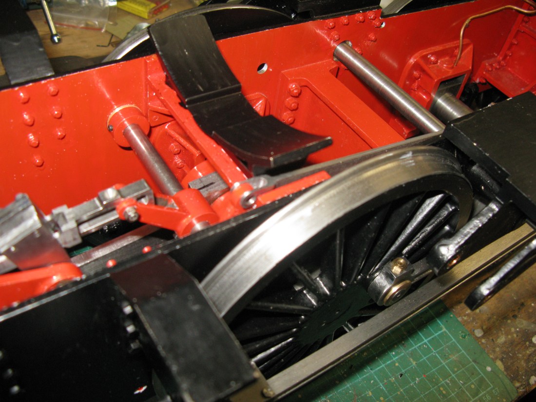
The weighshaft in position
The weigh shaft lever that operates the middle cylinder weigh shaft is an assembled component of two pieces, the boss and the arm as seen below.

This silver soldered together and the boss is held onto the weighshaft by a 4 BA grub screw in the bottom of the boss. The profile for the arm was cut on my little CNC mill.
The weighshaft link is a 5/16″ deep bar with a fork at each end to connect to the arms of the levers. I made mine from solid bar which turned out to be a lot of machining to achieve the forks on the end of a 3/32″ wide bar.
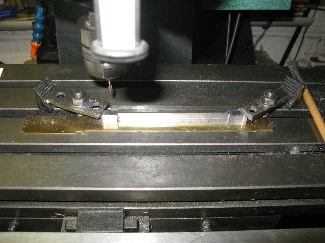
The first machining was to reduce the stock material to produce the 3/32″ wide link.

First side reduced (clamps put aside)
second side reduced
The machining was done against a fence on the mill table with the final operation bringing the fork ends down to 13/32″ overall.
Next the forks were milled out.
The holes for the pins were then drilled and reamed and finally the radius put onto the fork ends.
putting the radius on the fork ends.

All that remains to be done is to give the link a polish.
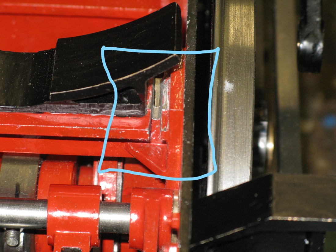
The link was made as drawn and I found the fork end would not fit into the gap between the frame and boiler saddle which was narrower than the drawn dimension. To overcome this I made the fork end narrower and fortunately there remained sufficient material on the fork for this to be successful.
Tight fit of the link fork between frame and boiler saddle
The next task was to try to assemble the connecting link to both weighshaft levers and in doing so numerous problems arose. There were at least four “pinch points” or places where fouling occured and the movement required to operate the expansion link turned out to be insufficient.
Dealing with the fouling points first. The connecting link bottomed on the stretcher and required a slot to be made to allow it to move over the required range. This slot was the full depth of the top web. Fortunately the the stretcher is well reinforced with webs so the slot would have a marginal effect if any on the stretchers job. The slot was filed and took quite a few hours of patient work.
Slot cut for connecting link to sit into
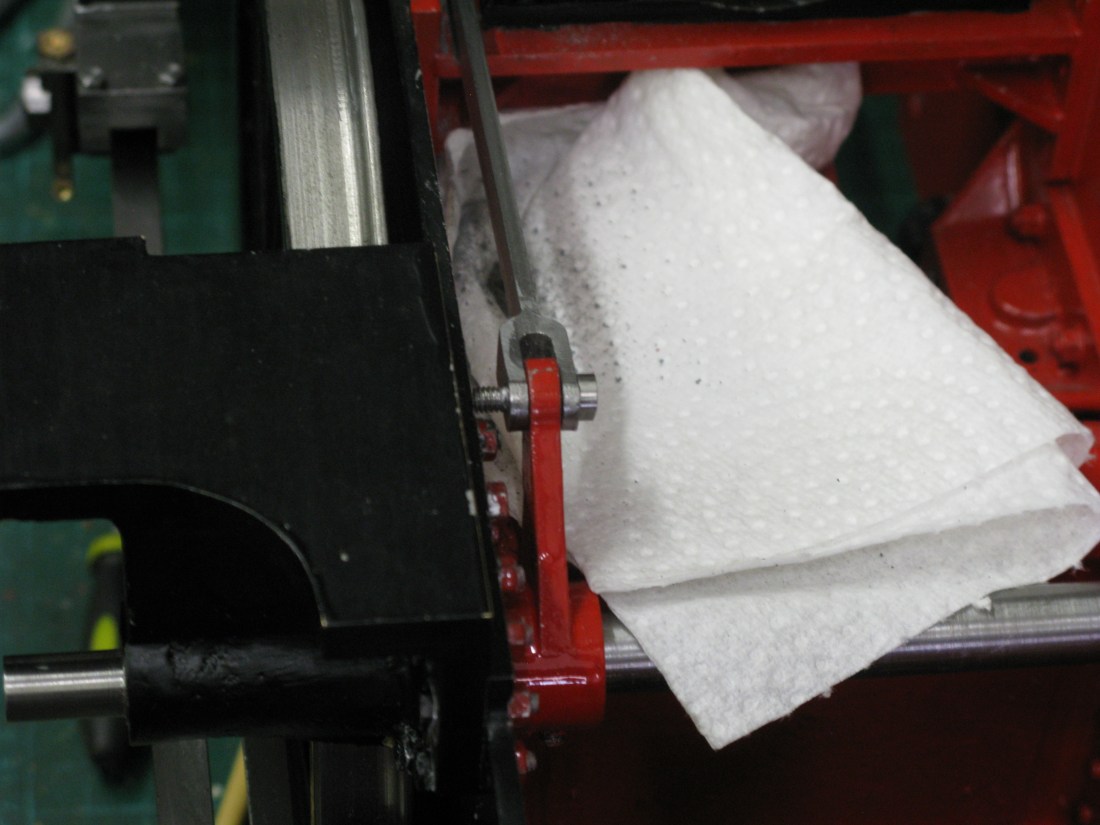
The next fouling point was the fork at the middle cylinder weighshaft end. The fork was not long enough to allow the angular movement and the lifting arm fouled the fork bottom. This required the fork bottom to be filed at an accute angle and square to relieve the foul.
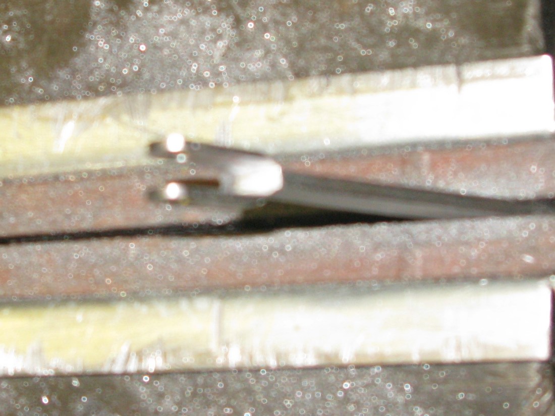
Sorry about poor picture its an enlargement but it does indicate the amount of relief that had to be filed away
The next two fouling points were from the nuts on the end of the fork pins. The front fork nut comes up against the stretcher and thus limits the movement of the lever and the rear fork nut fouls a fixing bolt nut for the weighshaft bracket again limiting the movement of the lever. I will return to a solution later as with the nuts off the total movement of the midddle cylinder weighshaft could be checked and I found that the movement could not achieve the full travel of the die block in the expansion link.

Fouling point before grinding away 1/8″ of the stretcher
There is no information on the drawings about the required angular movement of the levers but fortunately I have a reduced full size drawing of the real loco full of lots of detail and it shows the angular movement of the levers as 70 degrees. Not being able to measure easily the angle on the assembled loco I resorted to measuring the chord of the angle and knowing the radius of the lever the angle could be determined.
In order to achieve a 70 degree angle a chord length of 1 11/64″ was required and initially I had nowhere near that until some of the fouls mentioned above were resolved. Now all these things were happening simultaneously so between the slot and the fork end each was being adjusted bit by bit to improve the angular travel.
The stretcher had to have about 1/8″ ground away for the front fork to move backwards a little more once the slot was done and this also gave clearance for a nut which was a 5 BA nut tapped at 4 BA to match the pin. The rear fork foul was cleared by cutting off the fixing bolt flush with the frame. The bolt was retained in place with superglue.
Rear fork foul between pin and bracket fixing bolt
With these modifications done the movement of the lifting lever was just sufficient to get almost full travel of the die block in the expansion link. The lifting lever was then drilled for a 1/16″ pin so that full travel of the die block in the forward direction was achieved which meant the reverse was short of full travel. It will not be until the loco is run will I find out if the valve movement for the middle cylinder is really OK. As well as the fixing pin Loctite was also applied as I did not think reliance on grub screws and a pin was sufficient. The lifting lever was also drilled and pinned.
Lifting arm and lever Left side and lifting arm right side
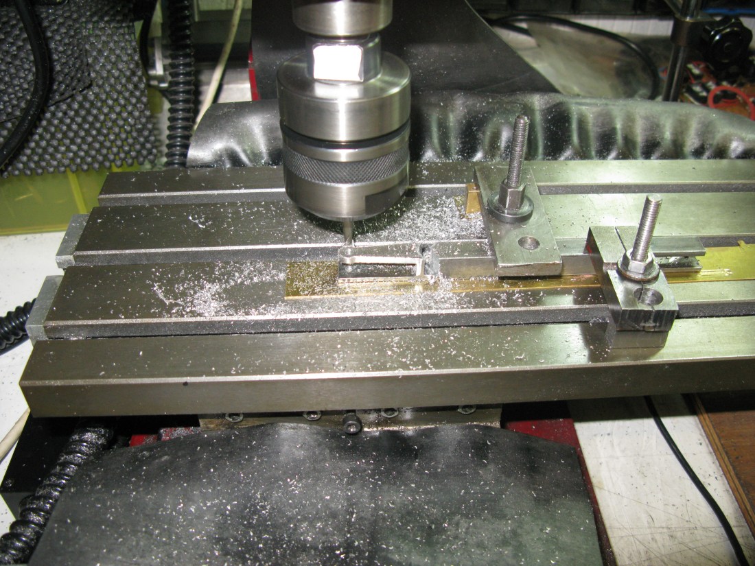
Like the preceding levers these are assembled items silver soldered together. The lefthand is a combination of the lifting arm and a lever whislt the right hand is just the lifting arm. The bosses for each were turned and drilled to match the weighshaft and then drilled and tapped for a 4 BA grub screw. The lifting arm was first slotted in the mill and then profiled on my small CNC mill.

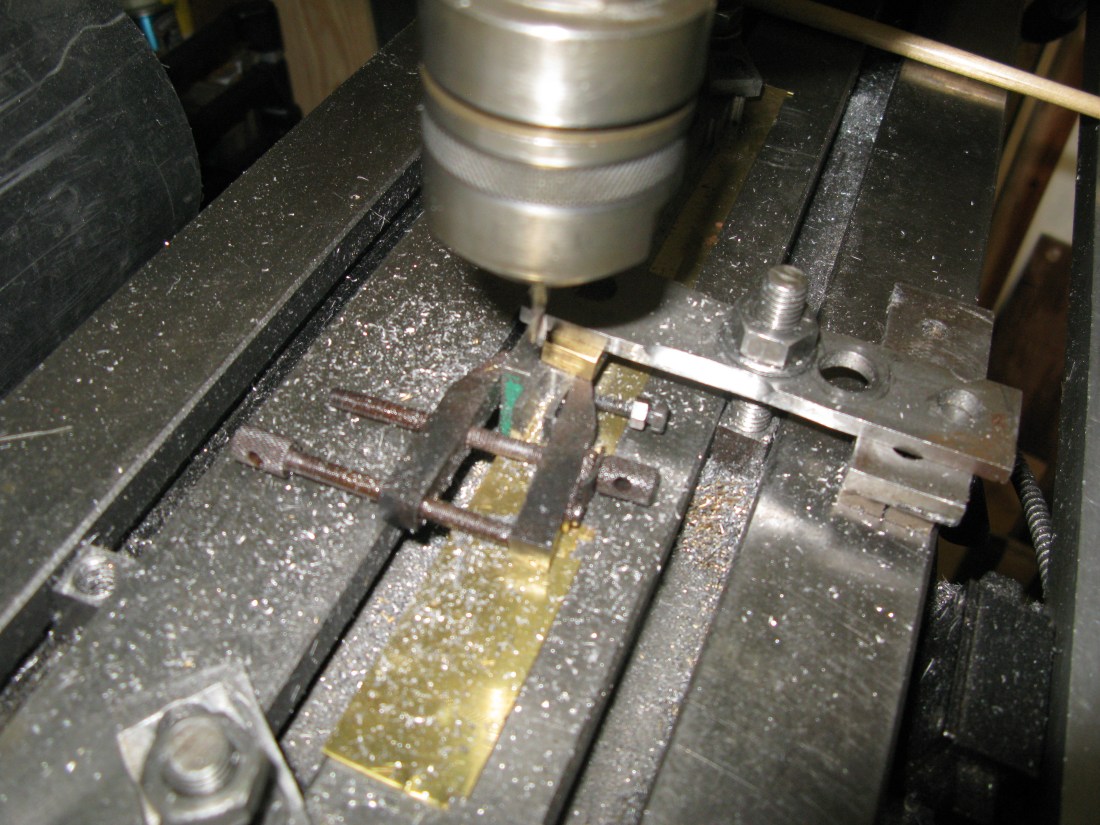
Slotting the lifting arm with a 1/8″ saw
In the picture above one end of the bar is being slotted, the bar was then turned around to slot the other end to produce two lifting arms.
Profiling a lifting arm
The lifting lever was produces in the same way.
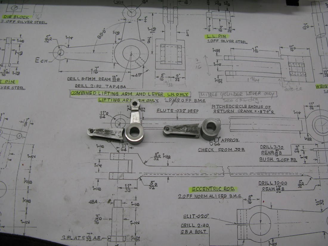
Component parts for both arms
The lifting arms are offset from the centre line by 1/32″ whilst the lifting lever is centrally located. The assemblies were silver soldered together cleaned up and give a bit of a polish.
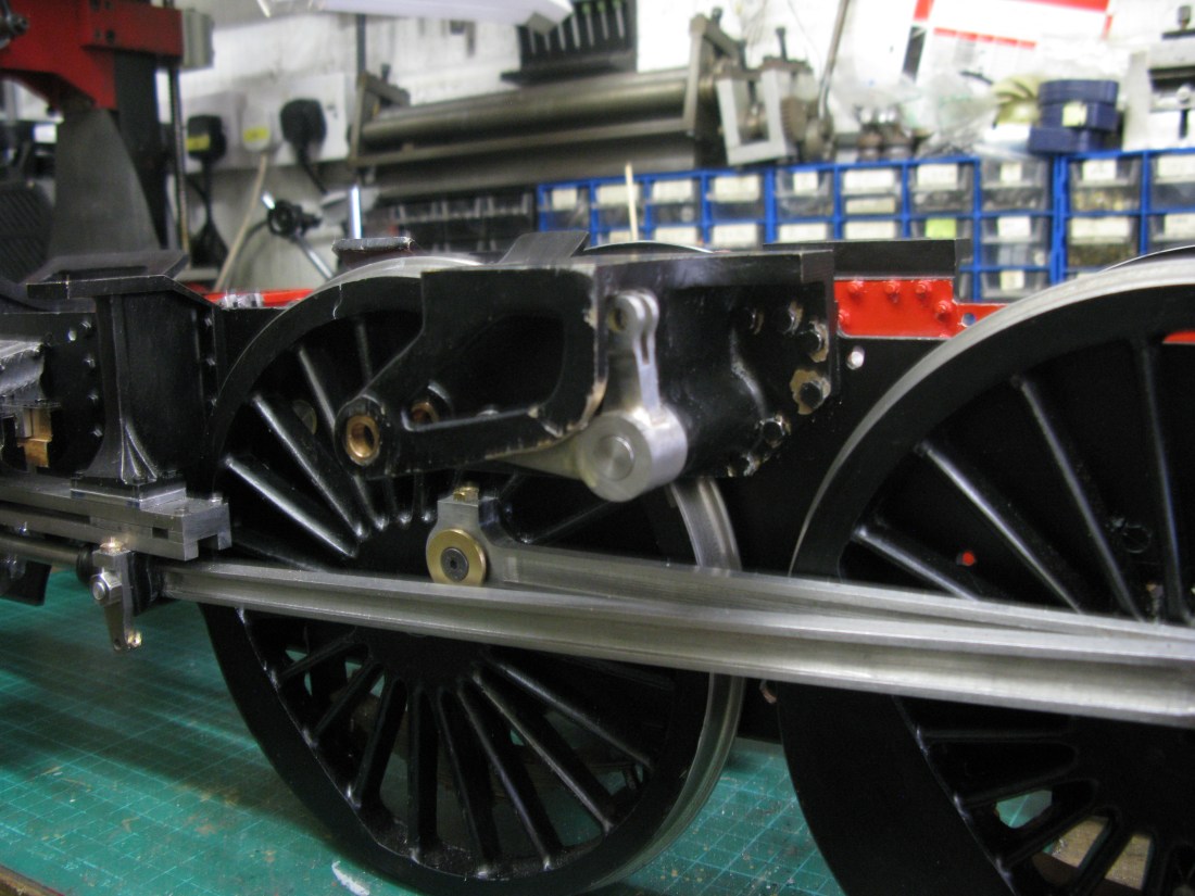
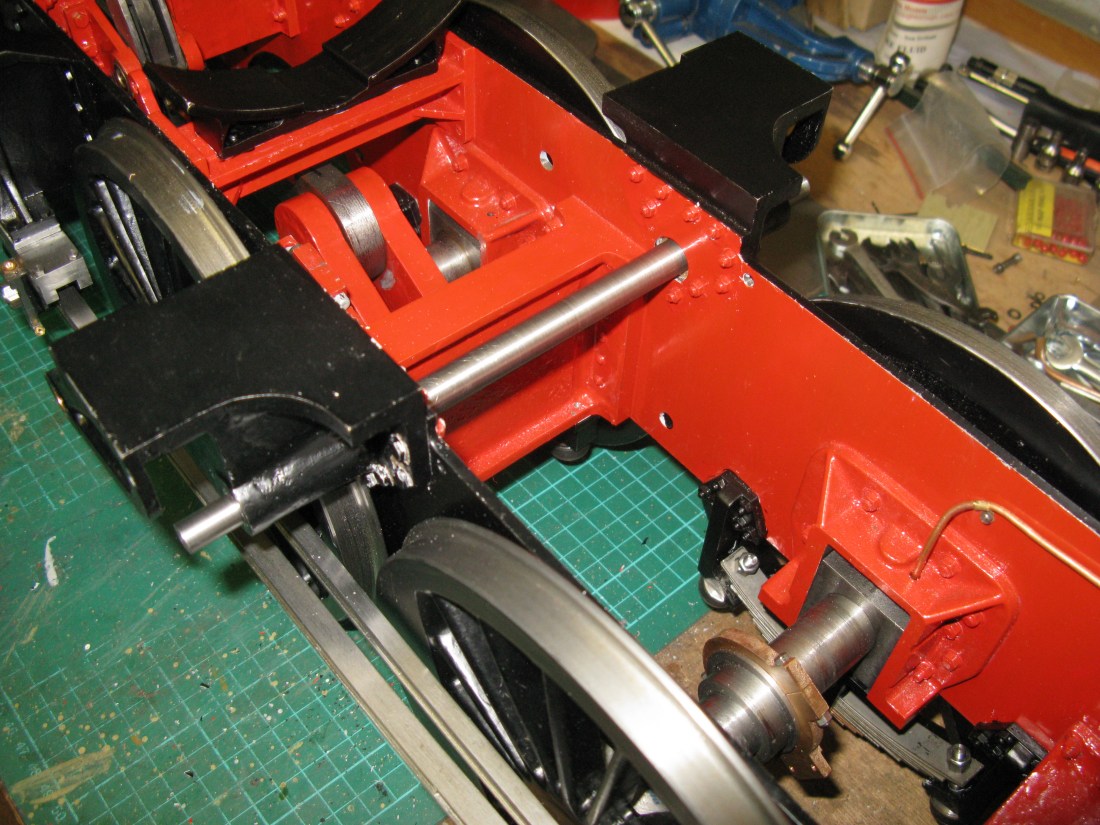
Lefthand lifting arm and lever mounted on the weighshaft
As might be noticed in the photo above the weighshaft bracket had to have its bottom radius relieved a little to enable the boss to clear it and slide onto the weighshaft. The slot for the lifting lever also had to have a little relief filed away to clear the lever ends. A bit of touch up painting to do later. Interestingly the drawing actually shows that the arm cannot be put onto the shaft as it fouls the bracket. I suppose the bracket could be taken off the frame and then assembled with the arm but that would preclude the arms ever being removed on a fully built engine as the bracket bolts would be nigh on inaccessible.
At the moment the arms are only held in place by the 4 BA grub screw. Once the radius rod and expansion link are made and the travel ascertained the bosses will be pinned in place.
