Cylinder block cladding.
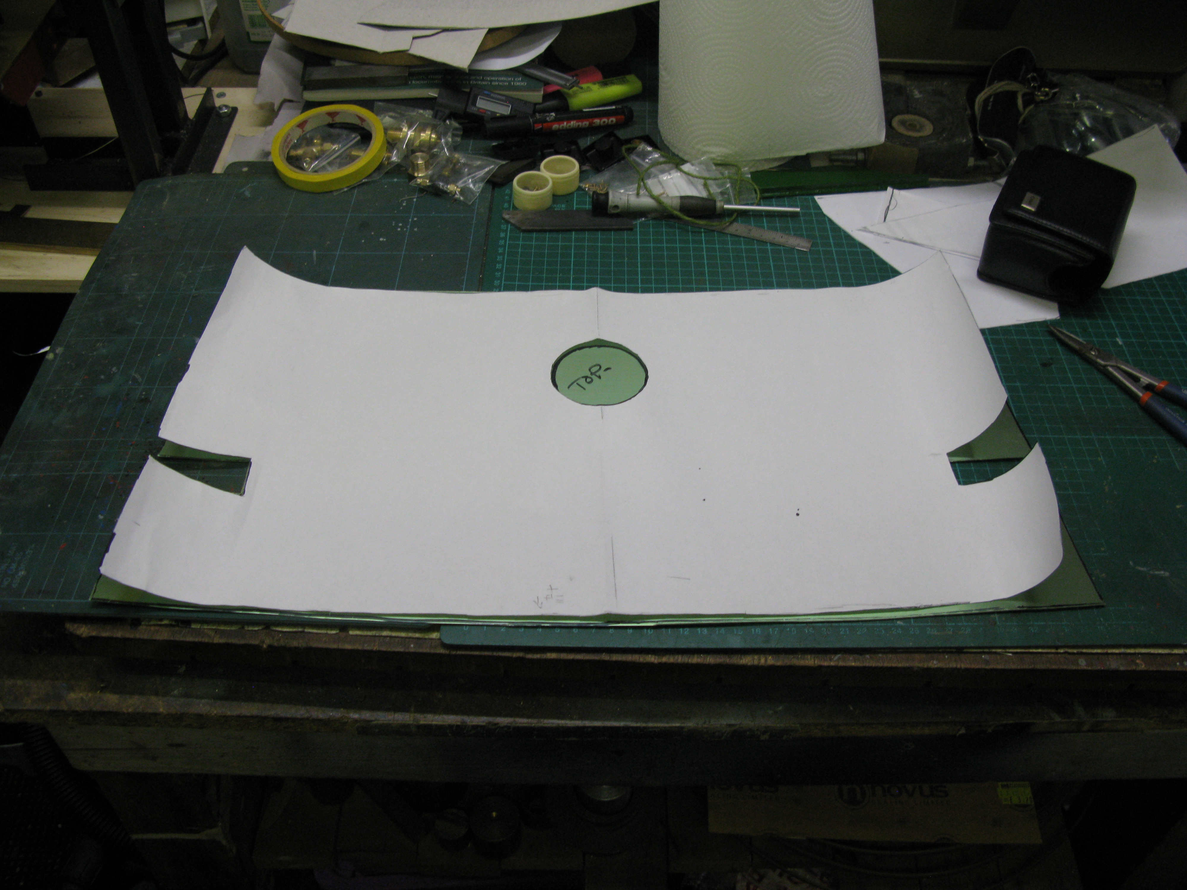
I am using 24 swg brass fo the cladding and to make the cladding for the cylinder blocks I first made a paper template by cutting the paper to width and then wrapping the paper over the cylinder block and marking out the fixing holes and drain cock holes by rubbing a pecil over the paper which leaves an impression of where the holes are. The paper is then glued to the brass sheet already cut to width and the holes drilled.
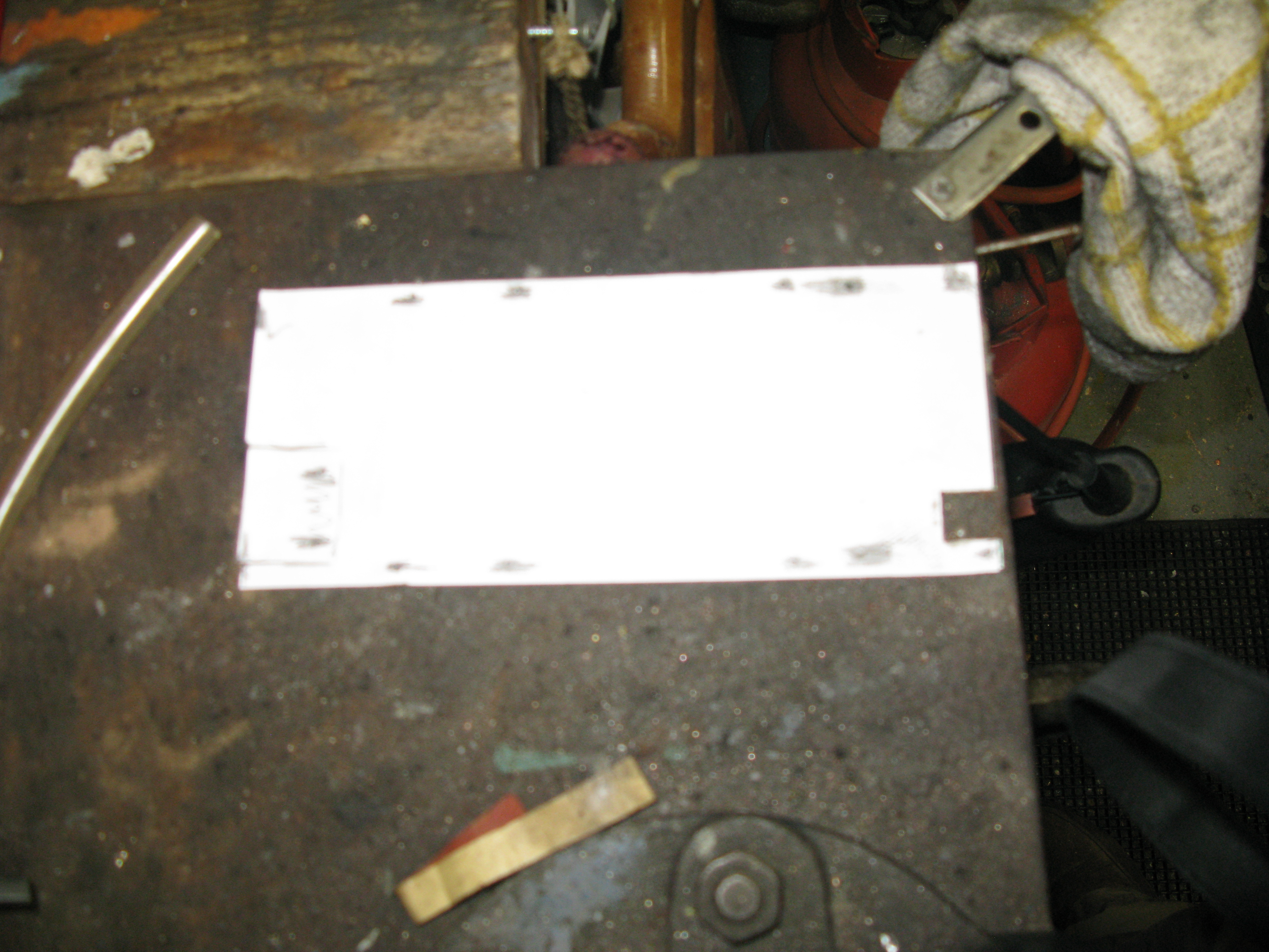
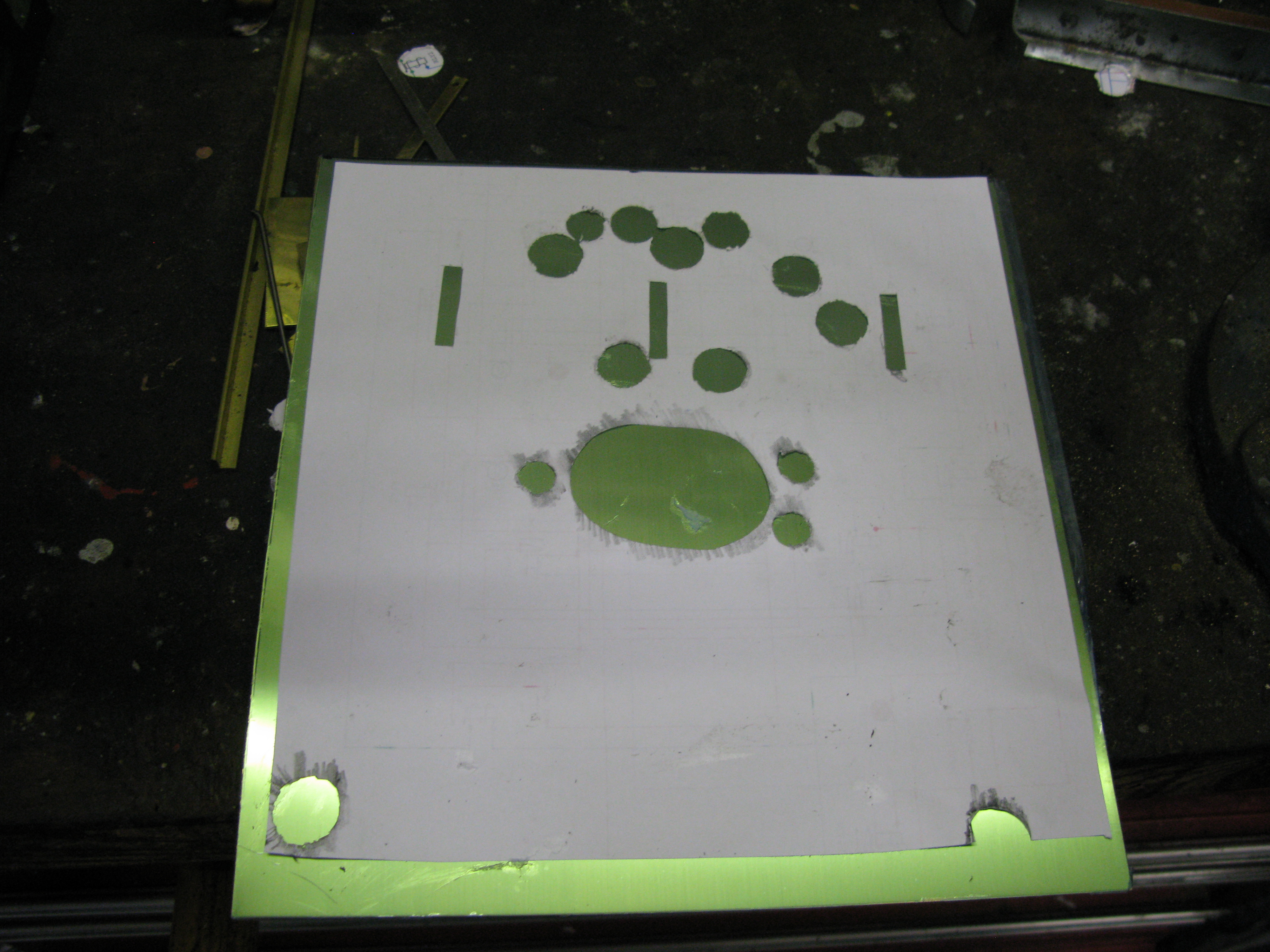
Paper template stuck to the brass sheet.
Two cut outs are required one at the bottom to clear the draincock operating lever and one at the top to clear the steam pipe flange. The top cut out in the template has been marked but not yet cut.
Once all the holes are drilled the brass sheet has to be bent to fit the curves of the block. I used a steel bar of similar diameter to put the curves in by hand pressure. Then its a case of offering up the cladding and checking the hole positions and the curves. So it’s on and off like the proverbial yo-yo ( I know that’s up and down) until a good fit is obtained and the holes all lined up with a little bit if filing here and there.
Once happy with the fit the cladding is still a bit springy so once all the fixing screws were in place for the bottom part of the cladding I used a gentle flame to reduce the springiness and get the cladding to lay flat on the front of the block. Then fitted the remaining screws and also reduced the springing at the top curve.

The fitted cladding
All fixing screws have washers and are small head 8 BA.
Once done the draincocks are fitted and secured in place with thread locker.
Before fitting them I painted the cladding. The brass was first etch primed followed by a grey primer. Then satin black top coat was applied. This is same process used for all other painted areas but this time a problem arose as the black wrinkled. So I rubbed the cladding down applied another coat of grey primer and tried again. It still wrinkled but not as much. A bit of research on the web provided advice that wrinkling is usually due to the underlying layers of paint still releasing solvent from the drying process. I had left 24 hrs between coates which I thought sufficent but obviously not. So I repeated the process leaving it longer and achieved a better result although there was some evidence of wrinkling but in areas that were not visible. I left it at that.
Another cladding task that can be done with progress as it is the cover around the steam pipe exiting from the smoke box.
An awkward shape to determin so a template was made from card.
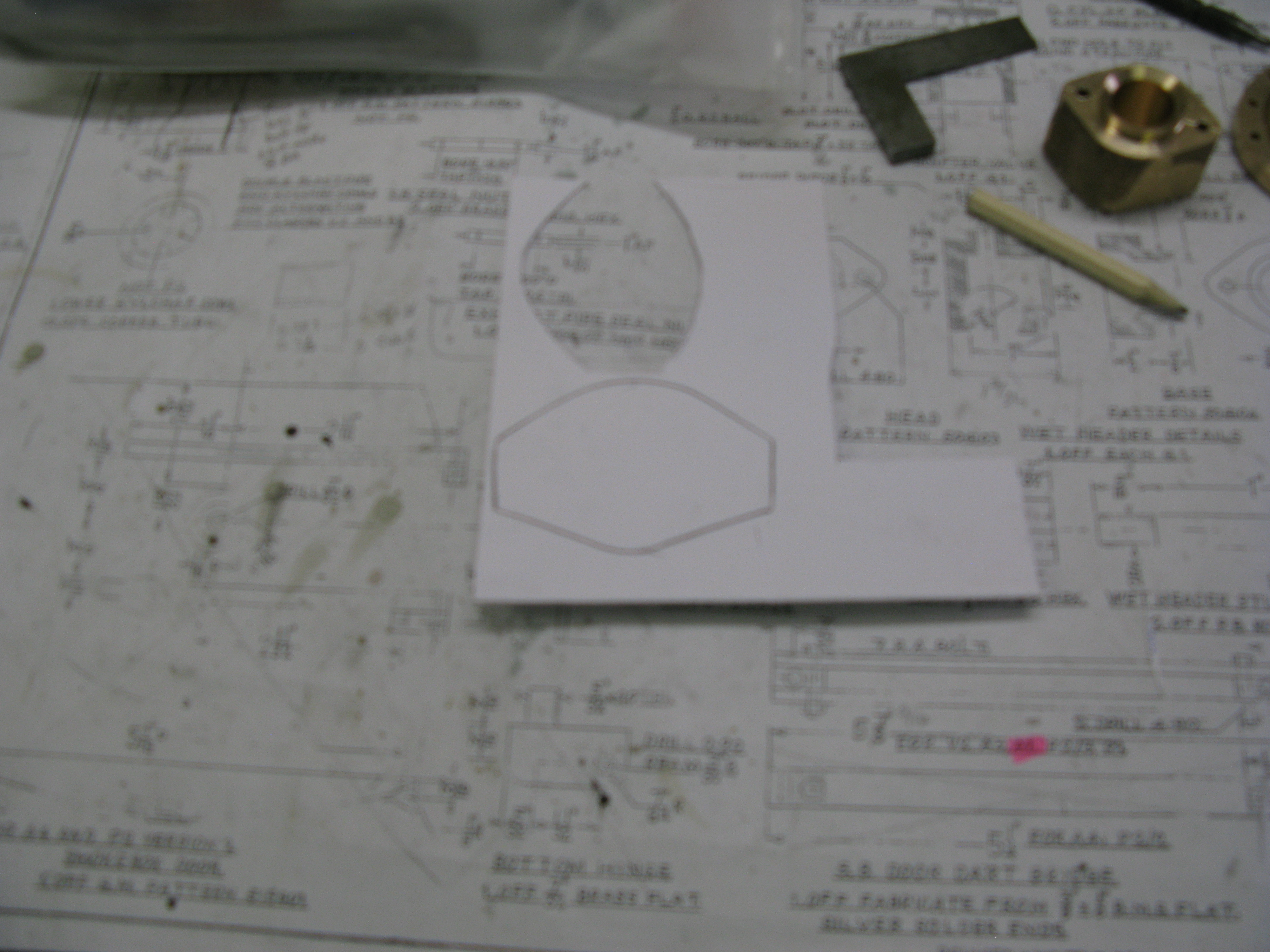
How to make the template though? Well I used plastacine. I moulded plastacine around the pipe and shaped it the smoke box and to give the angled shape down to the running board. With this mould to hand I carefully rolled the mould onto card tracing the line as I went.. The card was then cut and with a few minor adjustments to true it up on the job used to cut the brass sheet.

The card was glued to the brass sheet to enable the sheet to be cut and filed to the card template and trial fitted as seen above.
Satisfied that the cover fitted OK the flanges were cut by marking the sheet from the now available cover and soft soldered in place.

Soft solderinga flange in place
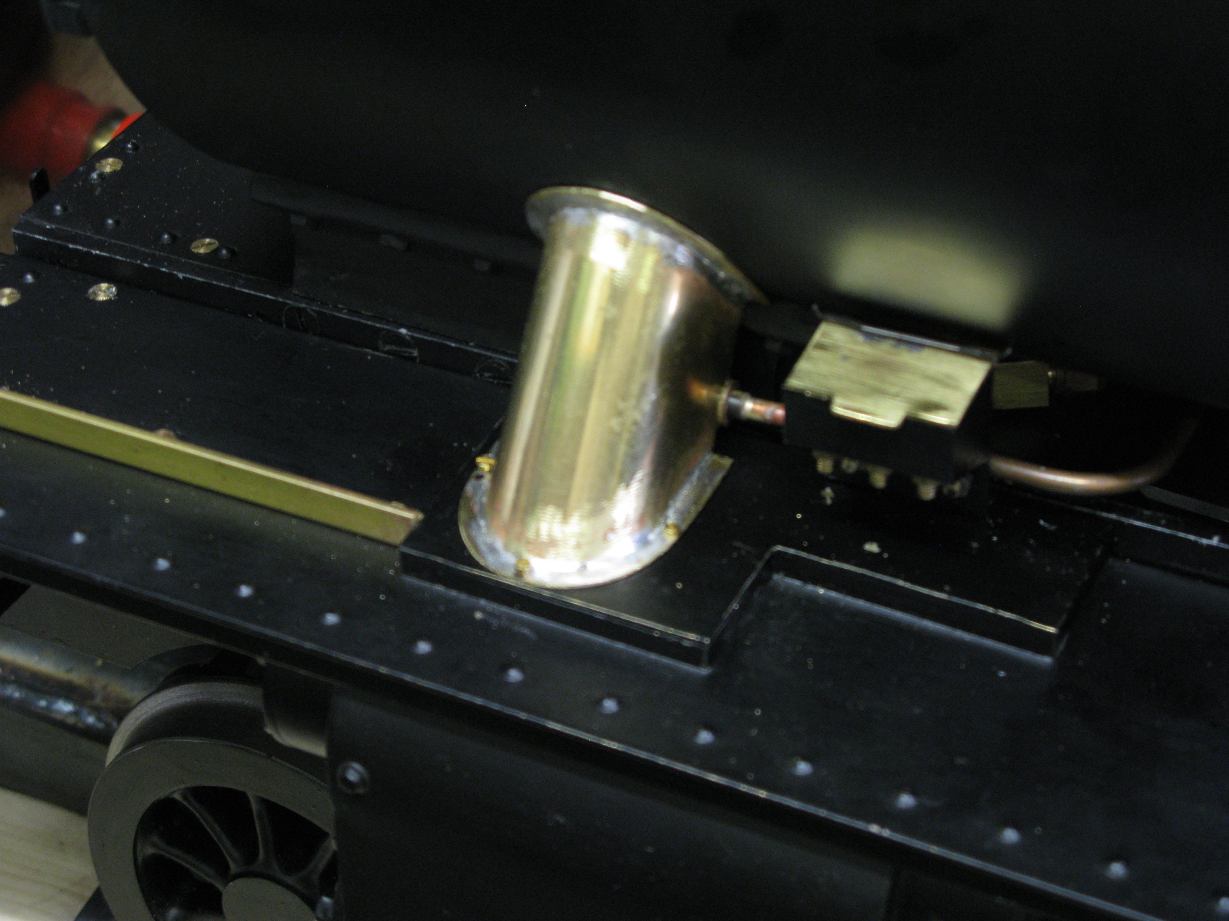
The finished article.
The cover is held in place with three 12 BA cheese head screws tapped into the running board. There is no fixing to the smoke box.
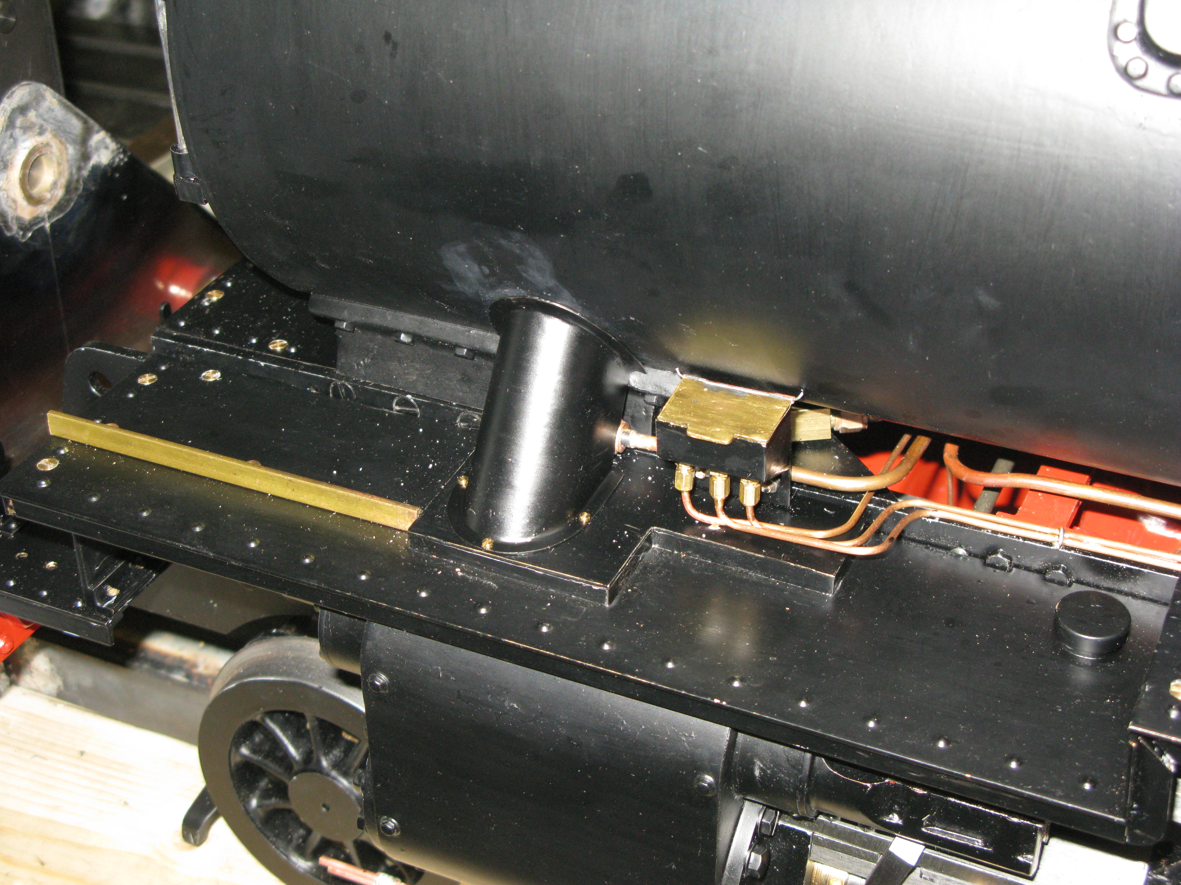
The finished fitted cover
Before finally fitting the cover the pipe was lagged with 1/8″ thick sheet lagging wrapped around and a small bit of wool lagging needed around the steam oil lubrication non return valve.
Barrel and firebox cladding
One of the first things to sort out on the barrel cladding is where does the taper start and finish. The barrel has a taper from front to back rising towards the back. At the fire box the firebox wrapper then tapers back down to the cab. The taper is not great, about 1/2″. However it is not clear from where at the front the taper starts. The GA drawing shows it starting from the smokebox and indeed a copy of the works GA drawing which I have in reduced form appears to confirm this. However looking at othe models and pictures of the full size it would appear that the first part of the barrel up to the dome or just before is parallel.
The boiler design has the barrel stepped which provides a 1/2″ difference in diameters of the front of the barrel to the rear of the barrel. This is the reason for the taper.
Another factor to have in mind is the clearance between the running boards and the cladding, there is not a lot of room. Also my boiler manufacture has a strap over its rolled barrel join underneath which interferes with the cladding going underneath. The boiler supports have a gap to allow some insulation between the support and the boiler, but the cladding has to be cut out to clear them. (They are not really supporting the boiler!).
Lastly there is the small matter of how to support the cladding as there are no crinolin rings in the design.
After much thought and chats with a fellow club member that has an A1 to a different design, I am thinking to have the taper start at the third boiler band from the front which is before the dome. This will give a parallel section at the front which can be done in one piece. The tapered section can also be done in one piece, and then the fire box wrapper with its rather difficult mating with the throat plate cladding and boiler barell taper.
One thing that came to light from thinking about the cladding and eyeing up the position was that the dummy sandbox fillers are too close to the cladding, not by much, but they will have to be relocated once the cladding is fitted.
All that remains is then the backhead cladding. This has its own problems of how to mate it with the fire box wrapper and how to get a nice rounded finish to the edges.
As a piece of cladding I chose to make the backhead piece first.
This involves lots of cut outs to clear all the fittings and a paper pressing was used to make a former by rubbing a pencil around all the bosses etc. This paper former was then glued to the brass sheeting and the cutout outs drilled (with sheet cutters) or sawn in the case of the rectangular cut outs and firebox hole.
Paper former for backhead stuck to brass sheet …fire hole door looks a bit wonky! Also the right hand blow down bush did not have enough paper! I did not have the paper square on the backhead when doing the rubbing.
When doing the cut outs I did them undersize initially and then with many fittings on and off the loco with adjustments made by filing or opening out holes either just on the diameter or moving them slightly one way or another the basic backhead was finally fitted around all the fittings.
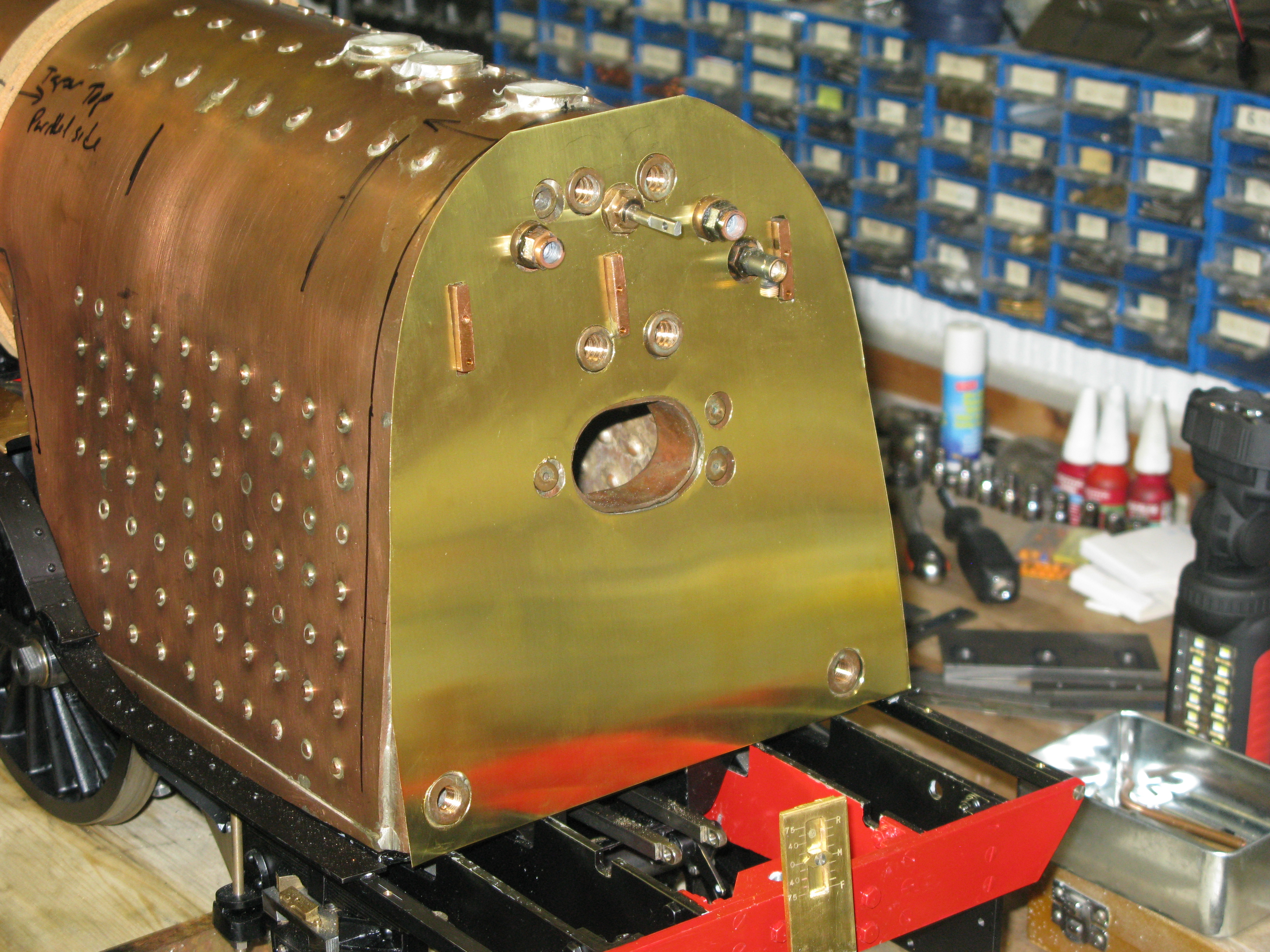
The basic backhead cladding ….. the outside edge still to be profiled
An update on the cladding thinking while I am awaiting some materials. I have a book on the Peppercorn A1’s by Peter Tuffrey which has photos and descriptions of, I think, all the A1’s built. Looking at those photos that have a resonable side elevation view it is clear to me that the boiler taper starts at the smoke box. So that settles my mind on how I will tackle the cladding on the barrel.
In order to stiffen up the backhead cladding and to provide a nice rounded edge to the firebox wrapper a 1/4″ dia anneald copper pipe was soft soldered to the periphery of the cladding.
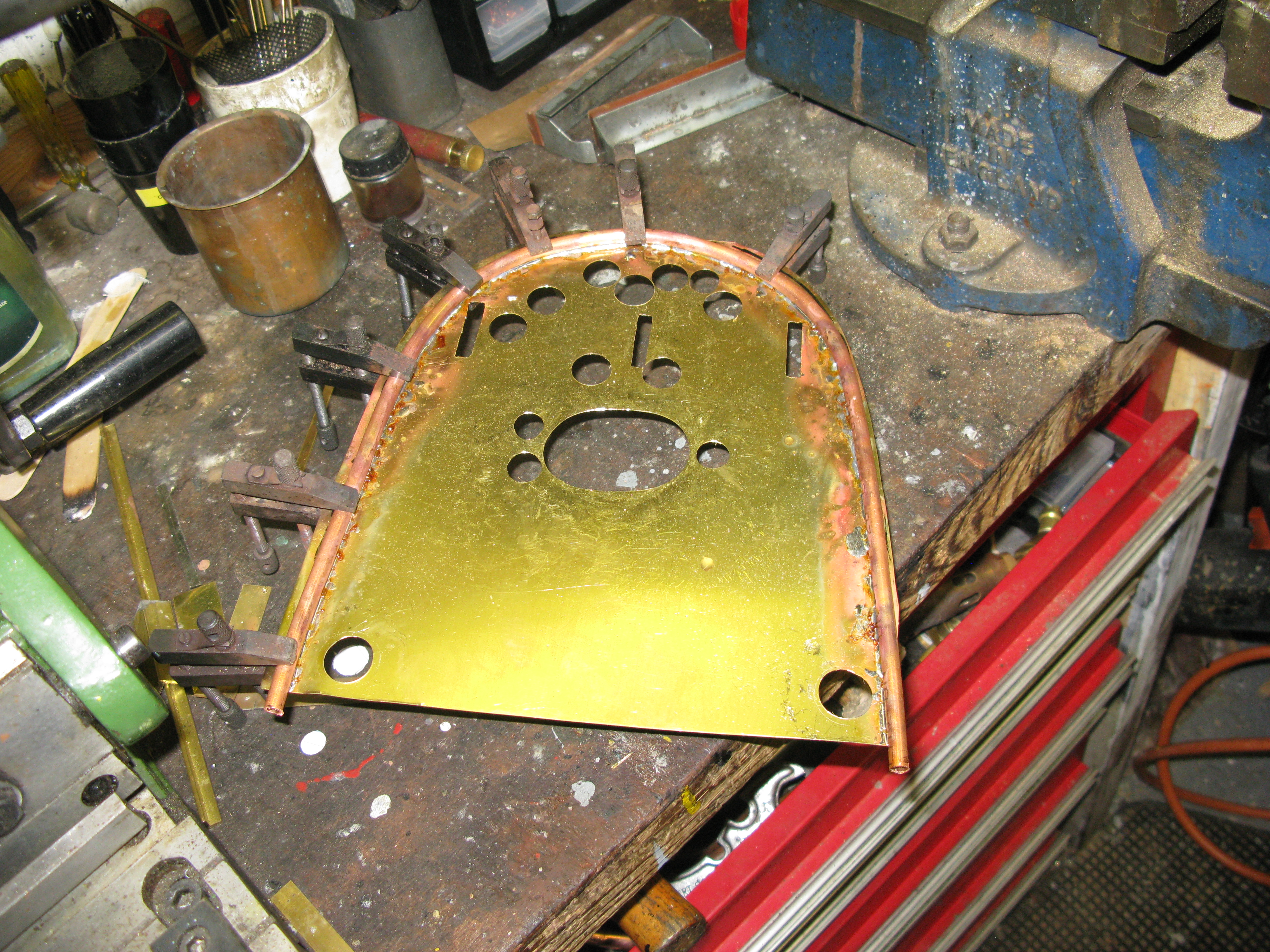
Soft soldering the copper pipe
I used the highest temperature soft solder I had which is 170 degrees melting point.
With the pipe in place the cladding was finished to size by cutting off the surplus sheet and then filing the joint to give a rounded edge.
The copper pipe also has affixed to it tabs which will be used to screw the firebox wrapper to. The tabs are set back on the pipe so the firebox wrapper abuts the pipe to give a smooth edge.
The tabs were put on with a lower melting point solder, 140 degrees melting point, to avoid disturbing the joint to the cladding.
Behind the claadding goes the insulation and this was cut from 3mm ceramic blanket. The required holes were punched out and the other rectangular cut outs and fire hole door cut with a model knife.

The insulation was trial fitted and then removed to fit inside the cladding piped frame.
The backhead cladding was then primed and painted with heat proof paint.
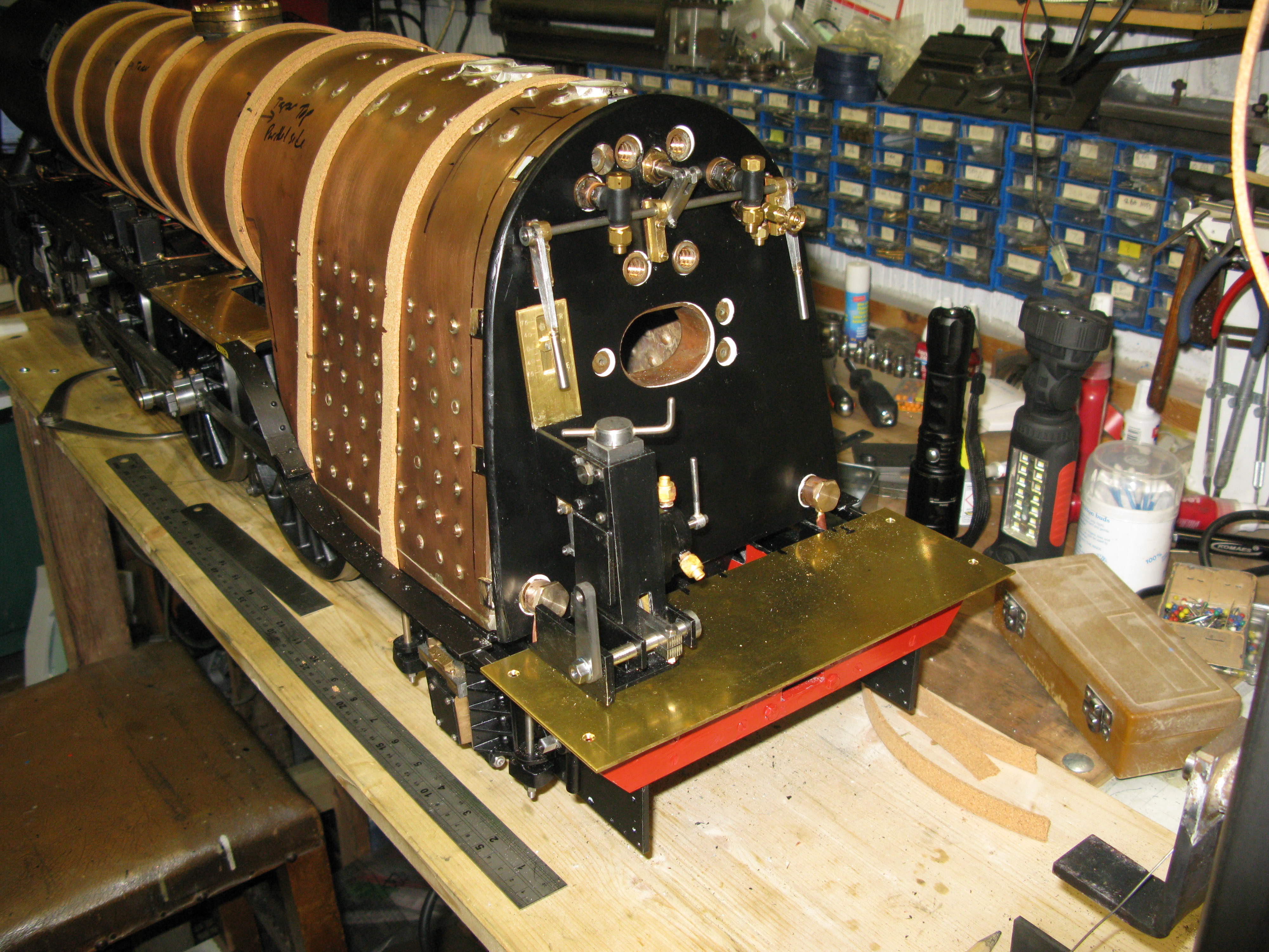
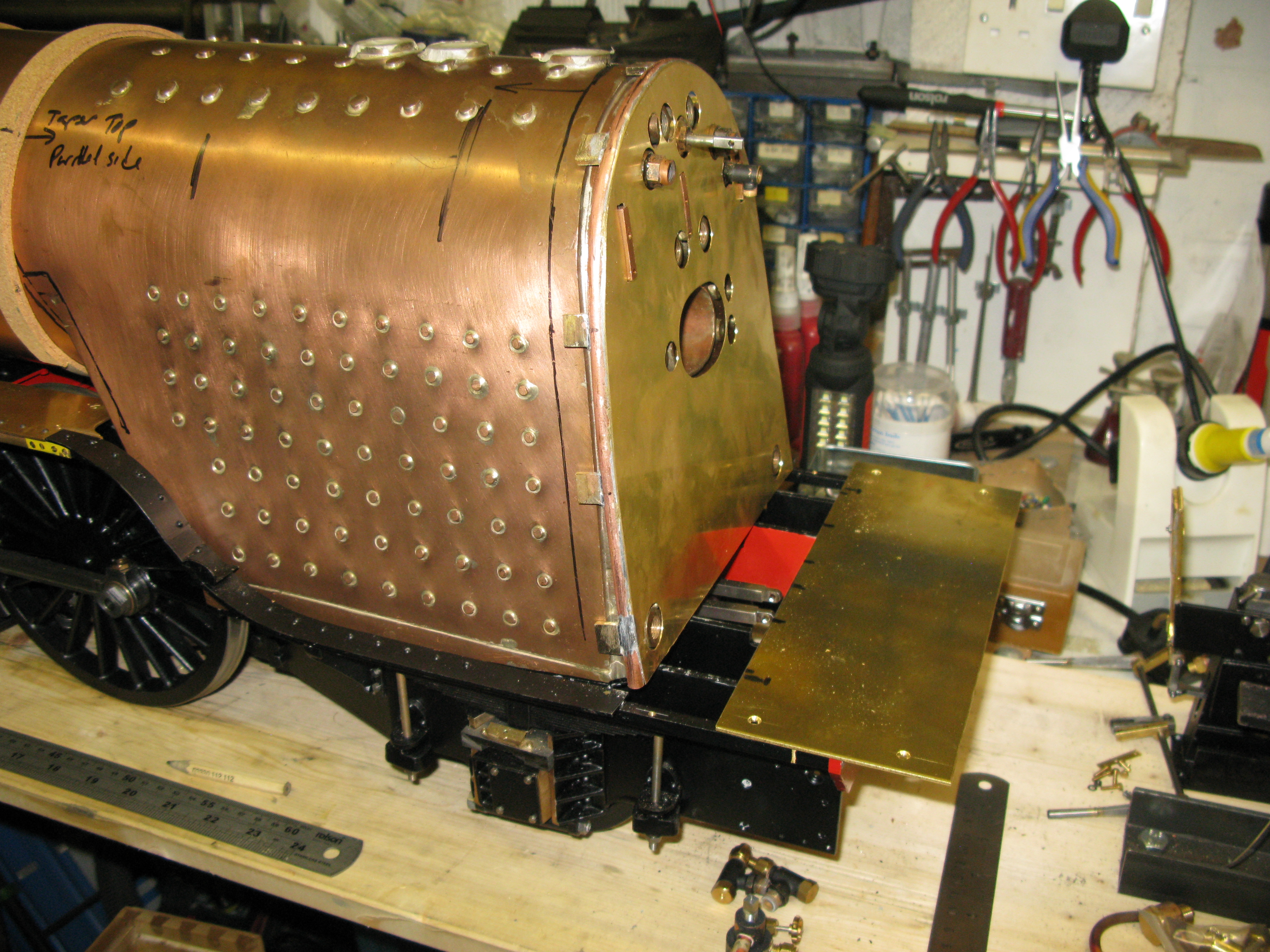
In the picture above the cab floor and reversing stand are not yet in their fixed position but the blowdown valves have been fitted.
Also in the picture can be seen cork bands around the barrel and firebox. As there as no crinolin rings as on the full size the cork bands act as a reasonably firm support for the cladding. The cork is under each of the boiler band positions.

The cork bands are built up to the required thickness, they are glued in place with superglue, and then sanded down to match the required taper for the front barrel and rear firebox.

The first bit of cladding being trial fitted.
The cladding is made from 27g brass sheet that I was able to source in 1 x 0.5 mtr size. It has a protective film on one side in green as can be seen. 27g is nice and flexible but also sufficiently strong so as take the rolling and be quite rigid in its rolled form.
Boiler inspection plates
On the cladding there are six inspection plates that need to be mimiced. There is no drawing for them so I had to make my own design by looking at fullsize pictures. There are three to mount on the rear firebox section and three on the section of cladding immediately in front of it.
I judged them to be about 5/8″ in diameter with a tapered side and having a bar and bolt holding them in place. In order for them to be clear of the boiler the depth could only be 0.140″ When fitted they would be soft soldered in place.
To make them I used 5/8″ dia. brass and turned down a 0.140 length to 1.2″ dia and then parted off to give a 1/32″ lip.The item was then reversed in the chuck and counter bored with a 1/4″ slot drill for 5/32″ and with a 3/8″ endmill ground with a 20 degree angle bored again to give the finished shape of a tapered side. Finally a 10 BA clearance hole was drilled in the centre.
To mimic the bar and bolt a piece of 16g brass was cut 5/16″ long by 3/32″ deep with a 10 BA clearance hole in the centre. A 10 BA c/s screw was then inserted from behind the plate to hold the bar in place with a nut.
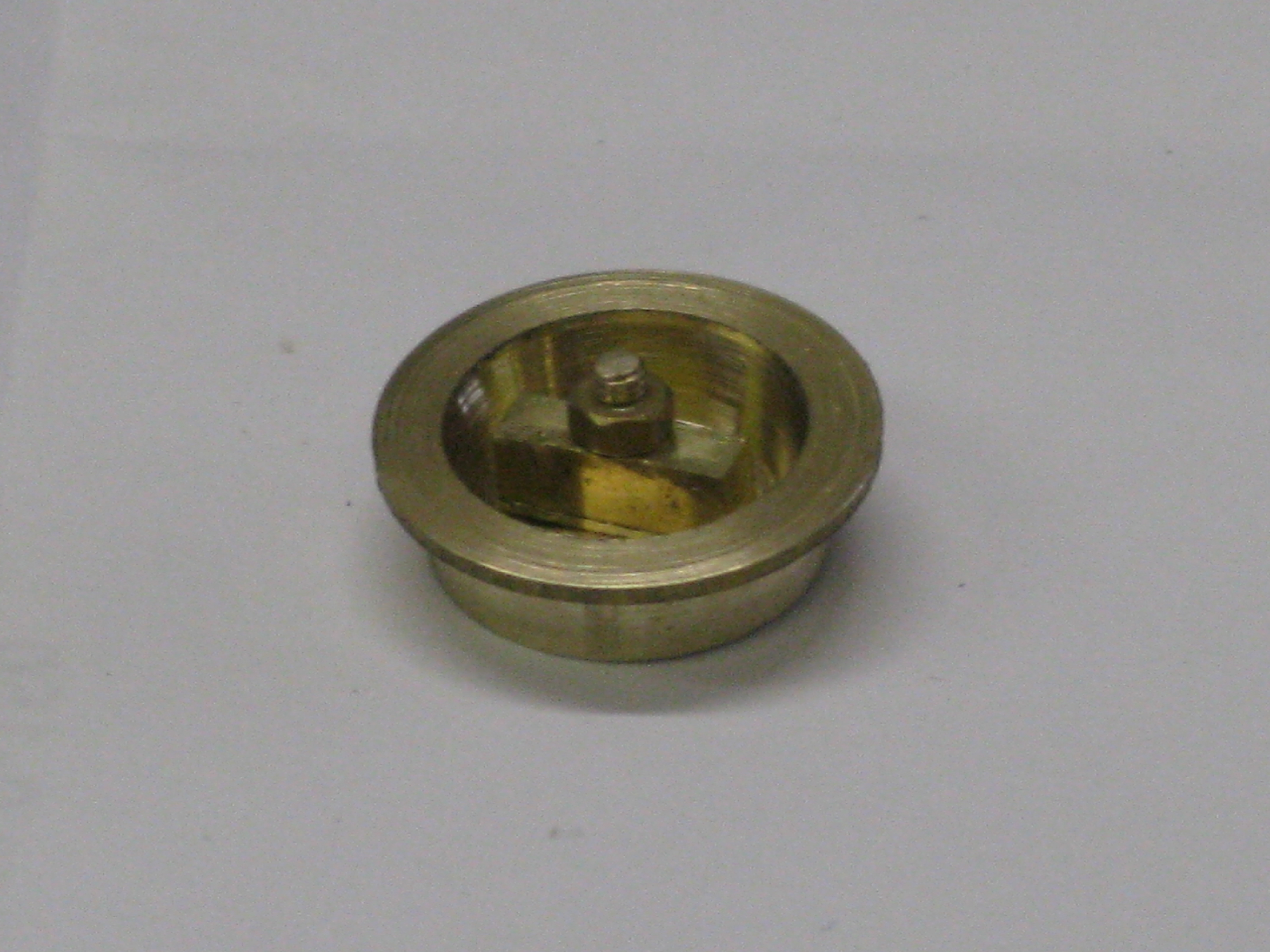
The finished inspection plate.

trial fit
Three fitted inspection plates
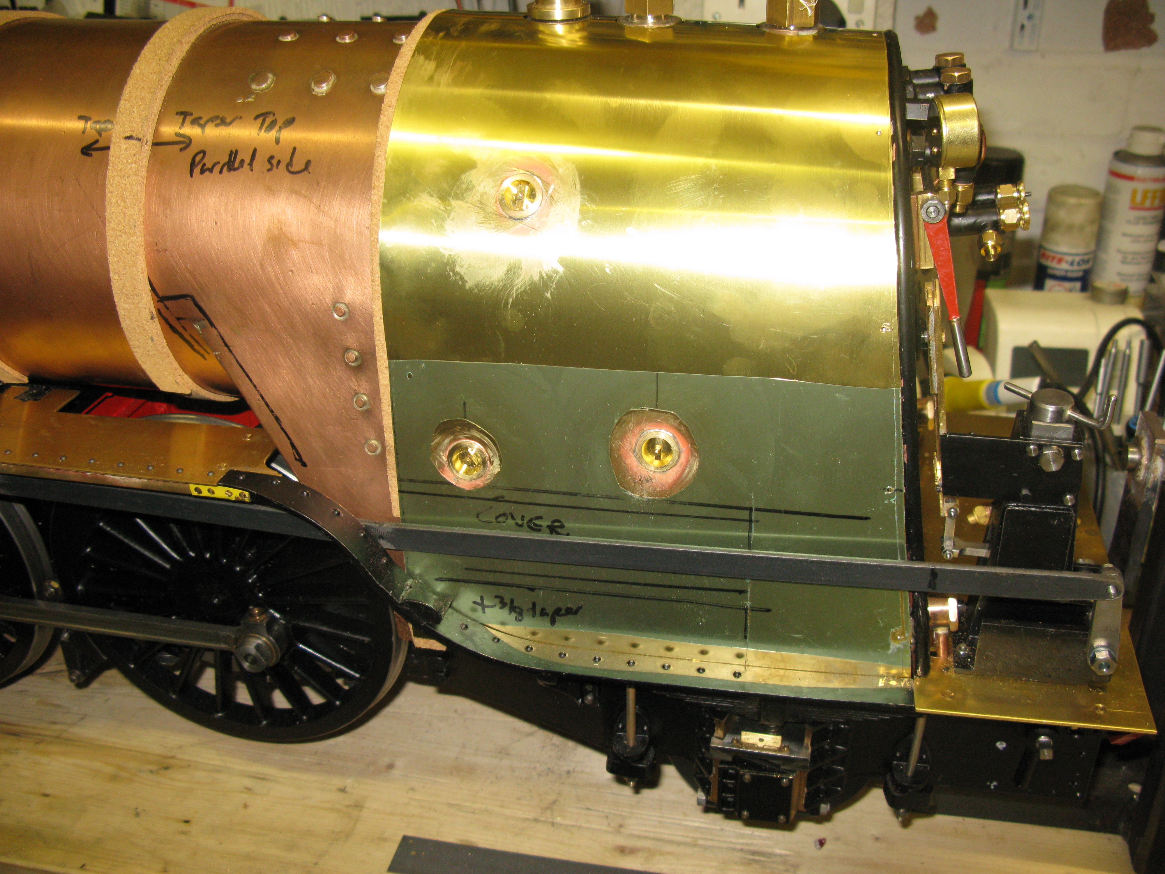
In the above photo the cover that fits over the reversing rod is marked out. The full size cover has very many fixing bolts along its top and bottom. I intend to use 10 BA fixings by soft soldering nuts on the inside of the cladding but only every other fixing position, the inbetween ones being dummy.
In case anyone wonders why I have a +3/8 taper note at the bottom of the cladding its because I cut the cladding square and forgot about the taper of the boiler. I will add a piece on the bottom which will cover that small bit of cork that can be seen which is just above the bottom of where the taper should start.
The insulation used is 3mm thick ceramic mat and it is cut to fit inbetween the cork crinolin rings.

I plan to do the cladding in sections and paint as I go.

First two sections painted. Trial fit of a boiler band as well.
The painting of the cladding is by spay painting using an airbrush. The bare metal has a two part primer first, folowed by three undercoates and then three top coates. Any runs being wet and dry sanded down before the next coat is applied. The finished colour is Darlington Green.
I use a home built spray booth made from a polythene box with a bathroom fan fitted in the rear with a filter box in front of it. The outlet from the fan is via flexible pipe which just hangs to the floor as I have no outside access from the workshop. I use a personal protection face mask which is rated to prevent dust and solvents whilst spraying.

Home mockup spray booth with rotary table
The boiler bands are made from 1/4″ x 1/32″ brass strip. The bands for the firebox end have to be fixed in a manner that can pull them tight as unlike the barrel bands they do not meet and cannot be pulled together. To fix them I chose to make a very small plate that screws to the underside of the ashpan frame with an 8 BA screw and also has a 8 BA clearance hole to allow a screw to fix to the boiler band. The band has a piece of 1/4″ x 1/4″ brass angle silver soldered to the ends drilled and tapped 8 BA to accept the fixing screw from the bracket. The band is cut slightly short to allow the fixing screws to pull it down tight onto the cladding.
The throat plate cladding is in four parts as I decided it was easier to make and fit. The radiused ends form one part each and then two plates which are joined by a tongue and slot at the middle.
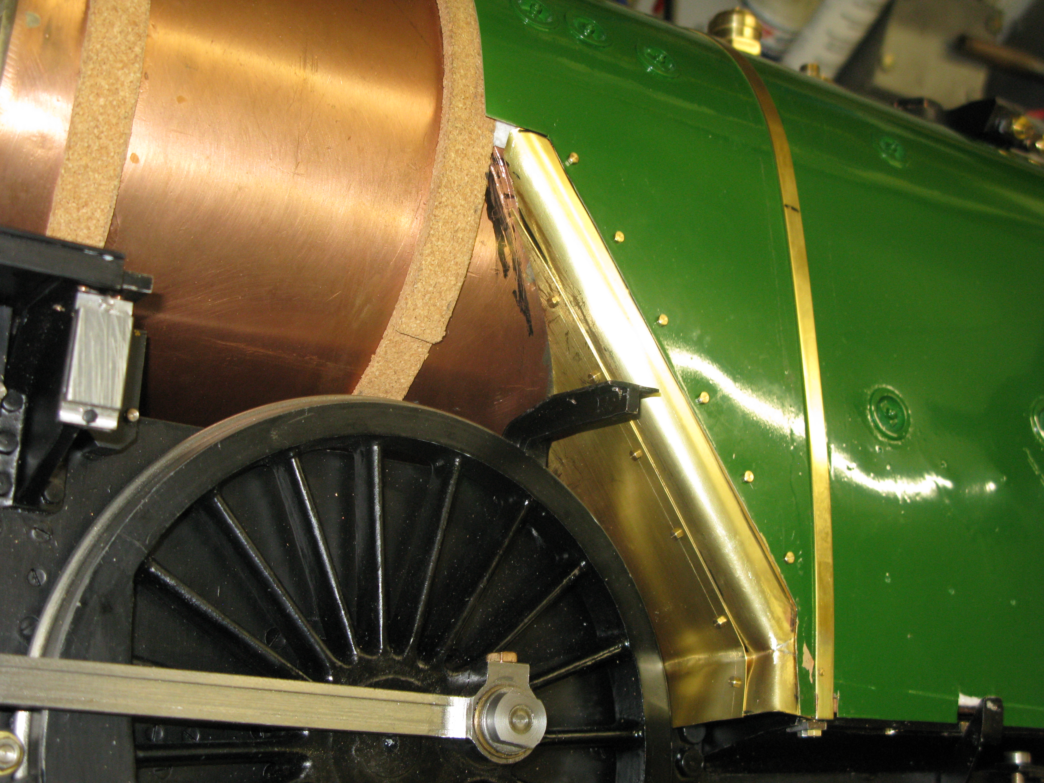
Trial fit of the throat plate cladding
At the moment the radiused ends use 10 BA screws with nuts soldered under to attach to both side cladding plates. I may change these to countersunk screws.
The next piece of cladding is the first part of the barrel which is tapered. However I have made life difficult for myself by having the boiler in place. This means a single piece of cladding cannot be fitted as there has to be a cut out for the boiler support saddle and this means it cannot be maneouvered in place as the bit that matches the throat plate cannot go in. So I am forced to make the piece that goes from the throat plate to the boiler band as one piece and then the tapered section threafter.

All the insulation in place.
The tapered section is proving to be difficult. Fierstly I had planned to make it as full size, i.e. from smokebox back but I have to change my plans as the taper produced makes everything too tight over the wheel arches and running boards so I have to make the taper start a couple of boiler bands back from the smokebox.
To make the taper, which is in the form of a truncated oblique cone I had intended to draw it out as a pattern but this proved to be impossible as the taper is quite shallow the peak of the cone is a long way from its base and it was longer than our dinning room table let alone for A2 paper that I had. So no chance of developing the shape by geometry. So the next step was to make a paper template by the good old “cut and try” (many times).
Paper template for the tapered section – cut outs to clear the boiler support.

Followed by cutting the brass sheet oversize to allow for trimming.
Having cut the brass sheet to the template (oversize) trial fitting could commence once the hole for the dome was cut. It was now that I found that the running boards had to come off as the wheel splashers were too tight against the cladding. Then I found that the running boards would not come off easily as the thickness of the insulation prevented the wheel rear splashers clearing the wheels. As it was mainly the cork crinnolin that was the main obstacle, the insulation being sort of crushable a few bits were cut out of the cork. This of course means the running boards will not go back on so the wheel splashers will have to be modified. Its the rear splasher that is the main culprit.
With the tapered section made and fitted the last section is the bit that joins it to the smokebox. This was going to be just a parallel part but luck and good fortune were shining down on me as when I fitted the middle tapered part the front end actually turned out to be higher than the crinoline cork. This meant the front section would have to match and that gave me my original intended taper on the top all the way from the smokebox.
The front section needed a cut out to allow clearance for the middle cylinder lifting link lever when in reverse , otherwise there were no other issues.
There is a cover that goes over the reversing reach rod alongside the firebox cladding. I ended having to make two as the first one turned out not to be deep enough to clear the reach rod. This came about because the reach rod had to have its set increased so that it did not rub on the boiler band. Its a bit of a pig to bend the Z corners due to the small lengths involved but patience and perseverance won the day using all sorts of bits of metal to hold, clamp and knock the shape into being.

The second version of the cover trial fitted
The cover is held onto the cladding by 10 BA HH screws the cladding having 10 BA nuts soft soldereed to the underside. There a many fixings on the full size but I have chosen to make every other one a dummy.
The final piece of boiler cladding at the front has now been fitted.

Also the reversing reach rod cover has been fitted. It may have to come off again when the cab is done as it abuts the cab at an angle and at the moment it has a square end.
The boiler bands are not all straight forward.. Ther are seven in all. The three that can be seen going around the barrel are simple as they they just go all the way round the barrel. The one over the firebox is screwed to a small bracket attached to the ash pan rim so it can be pulled down tight. Counting from the front, number two band is yet to be fitted and that is a simple one too but it is very tight to get in due to the steam lubricator pipe and inside lifting link lever rod causing obstructions. Number four is special as it has the dome in the way so this one has a ring around the dome attached to a band either side.

Lastly number five sits right over the boiler support saddle. To fit this one I put a small U hook on one end that catches under the cladding and the other end is screwed to the boiler saddle that emerges near the running board. The missing bands are currently in the paint shop.
The dome cover is a very substantial gunmetal casting that has to be fettled. It also has to have the interior machined out to fit over the dome. This was done on the mill with the casting clamped to the mill table.

With this completed it was then a case of many trial fittings on and off to get the form of the flange to sit cleanly around the cladding

The cover is held in place by a single 7 BA HH screw.
The inside of the flange has to be relieved so it gives clearance for the boiler band ring beneath it.
The cladding is now all fitted with the boiler bands in place. The first grab rail has been fitted.
