The tender is of the eight wheel design with a water pick up chute.
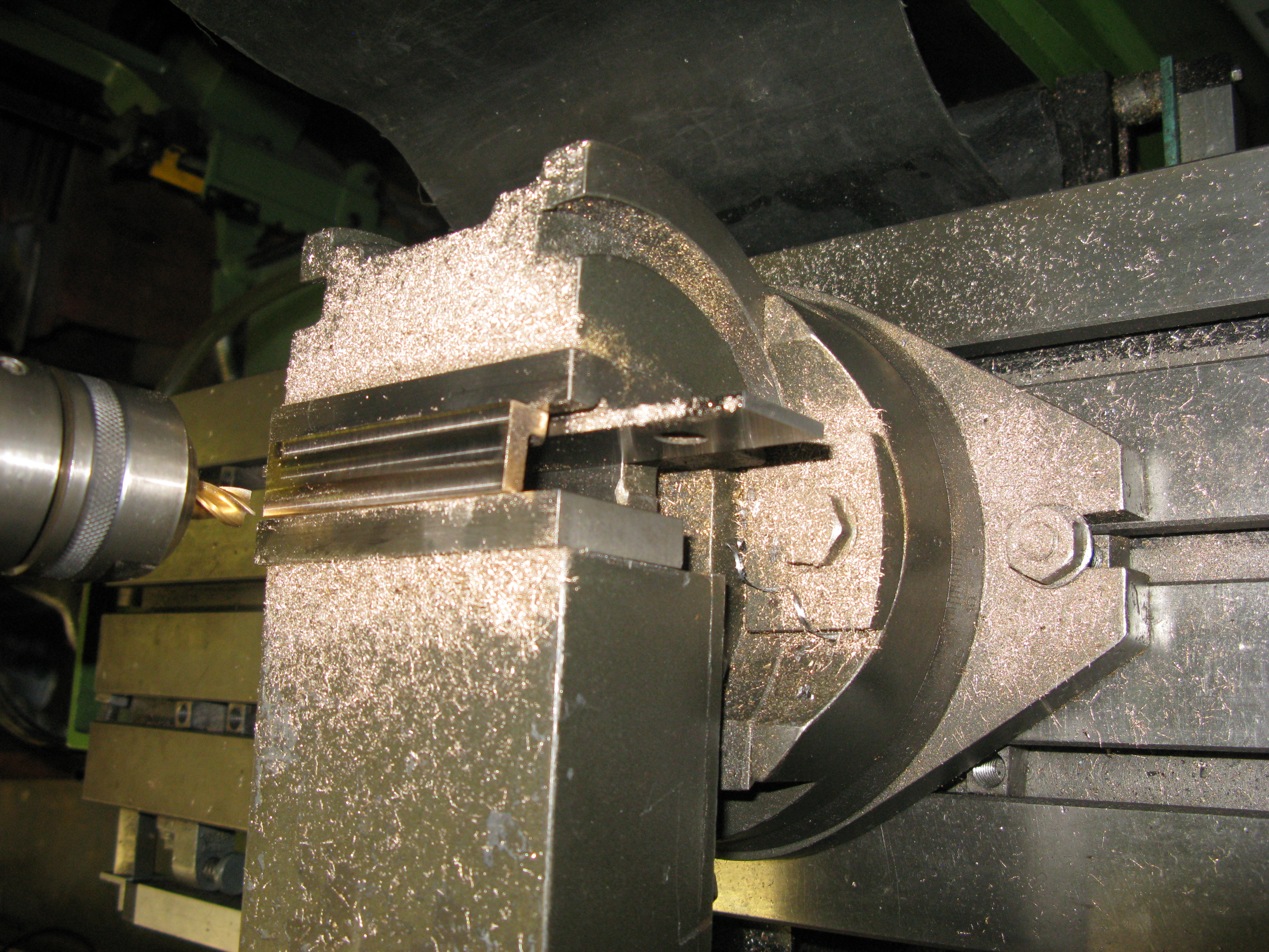
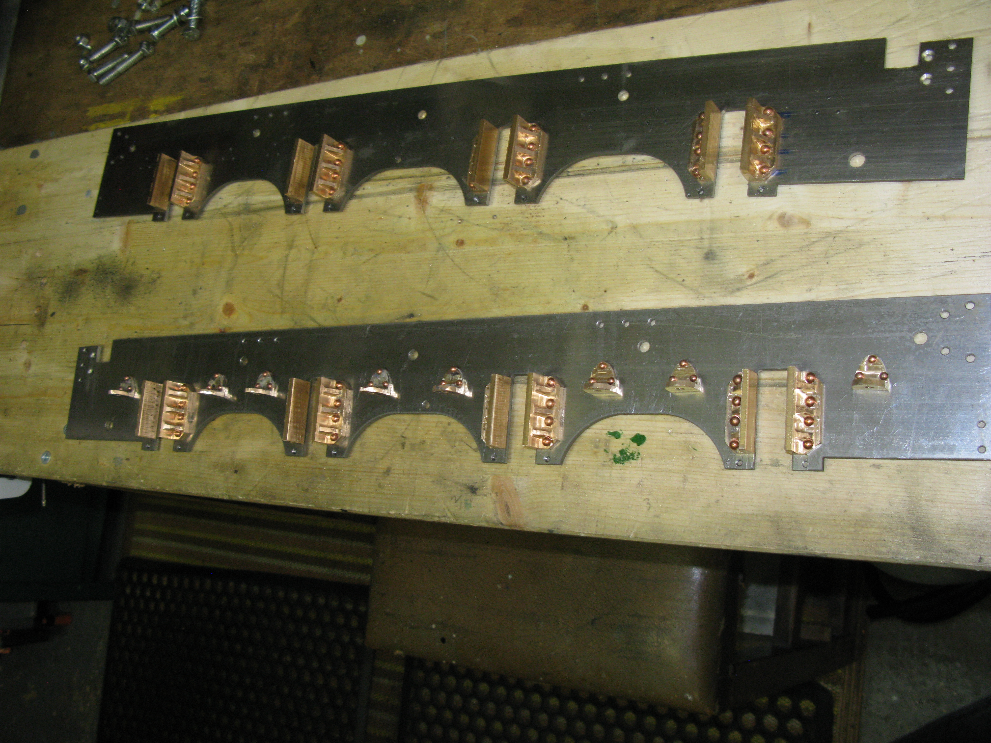
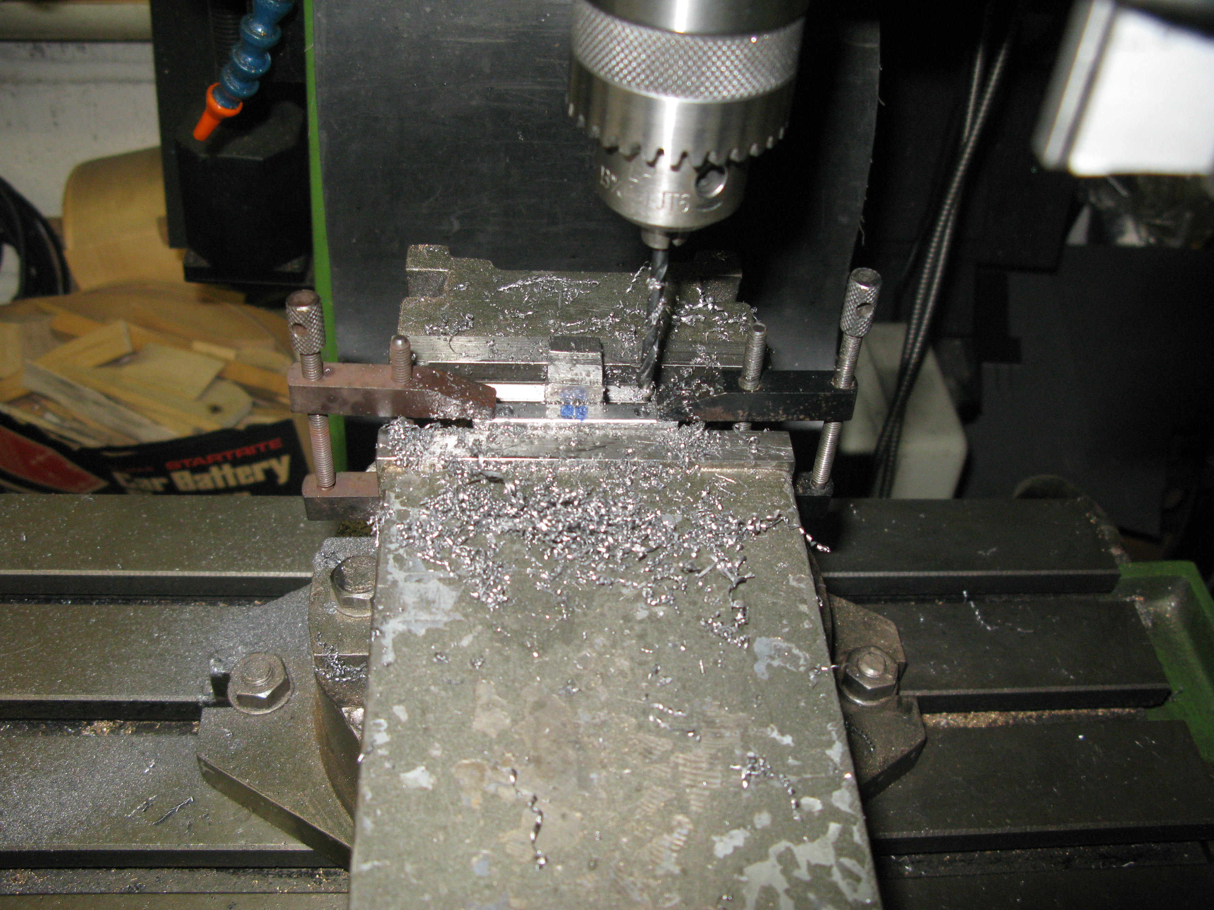
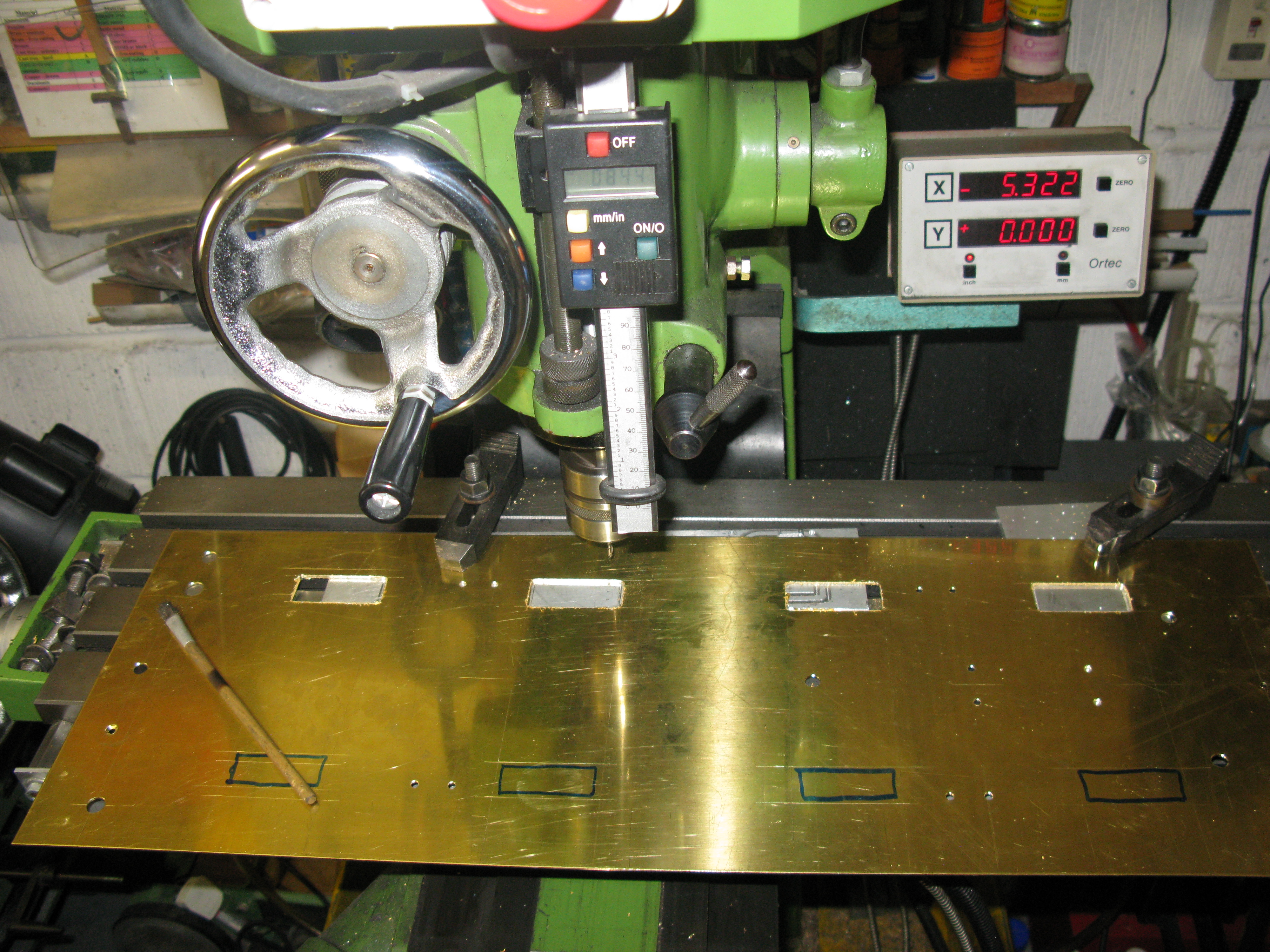
The frames have been water cut to obtain the profile and the first job is to drill all the various holes which I do by mounting the frames paired together on the mill bed with a sacrificial plate underneath to accept the drill bit going right through.
As the mill table movement is not sufficient on the X axis the frames have to be moved along the table to finish drilling the last set of holes for the rear axle and drag bar.
With all the holes drilled and deburred the next job is the horn blocks.

These are castings and they are cast as a pair end to end.
Looking at the webs and offering up against the drilled holes in the frame it looks as if the outer webs are going to interfere with the holes as they are too thick and near the end of the block.
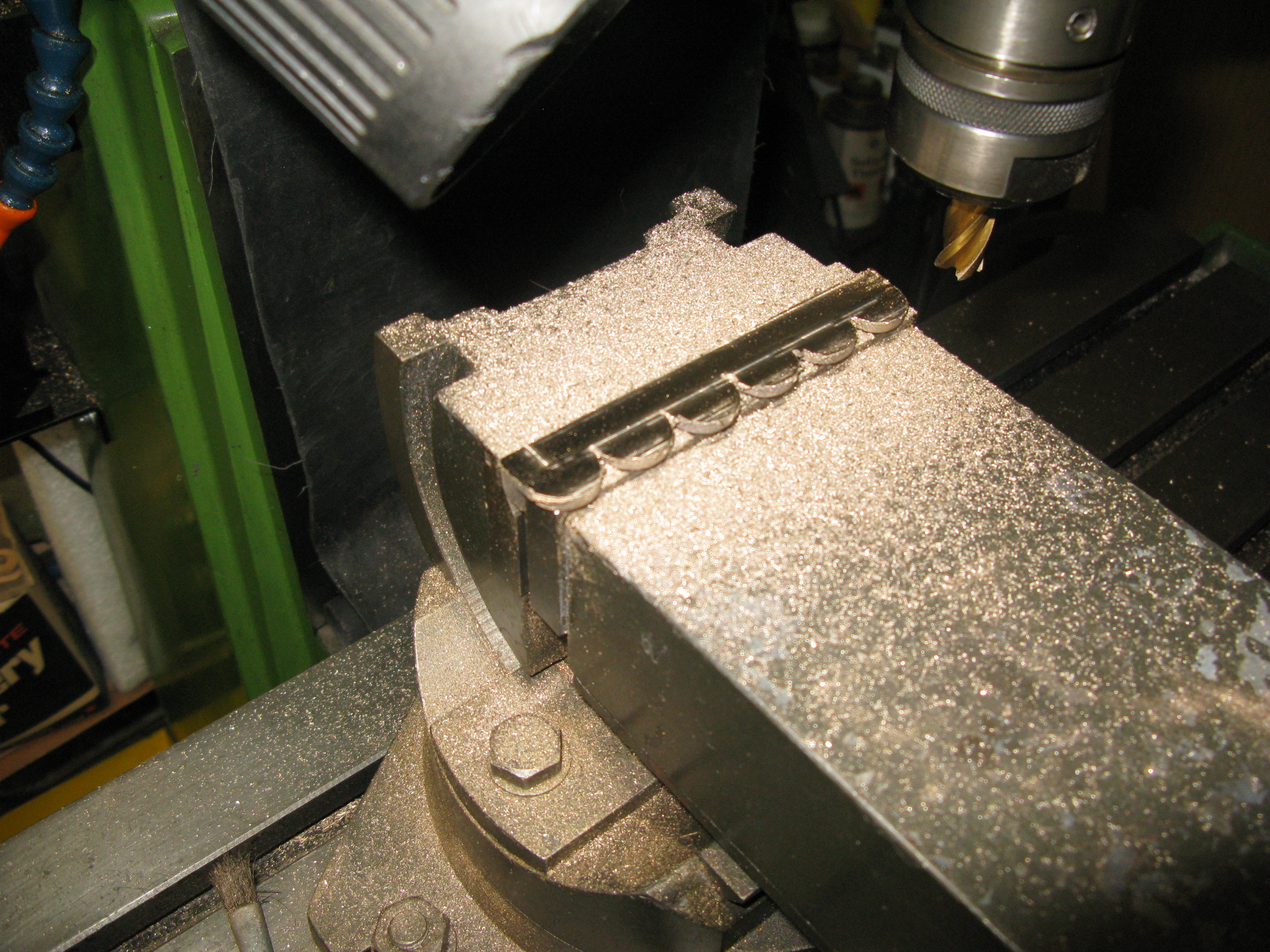
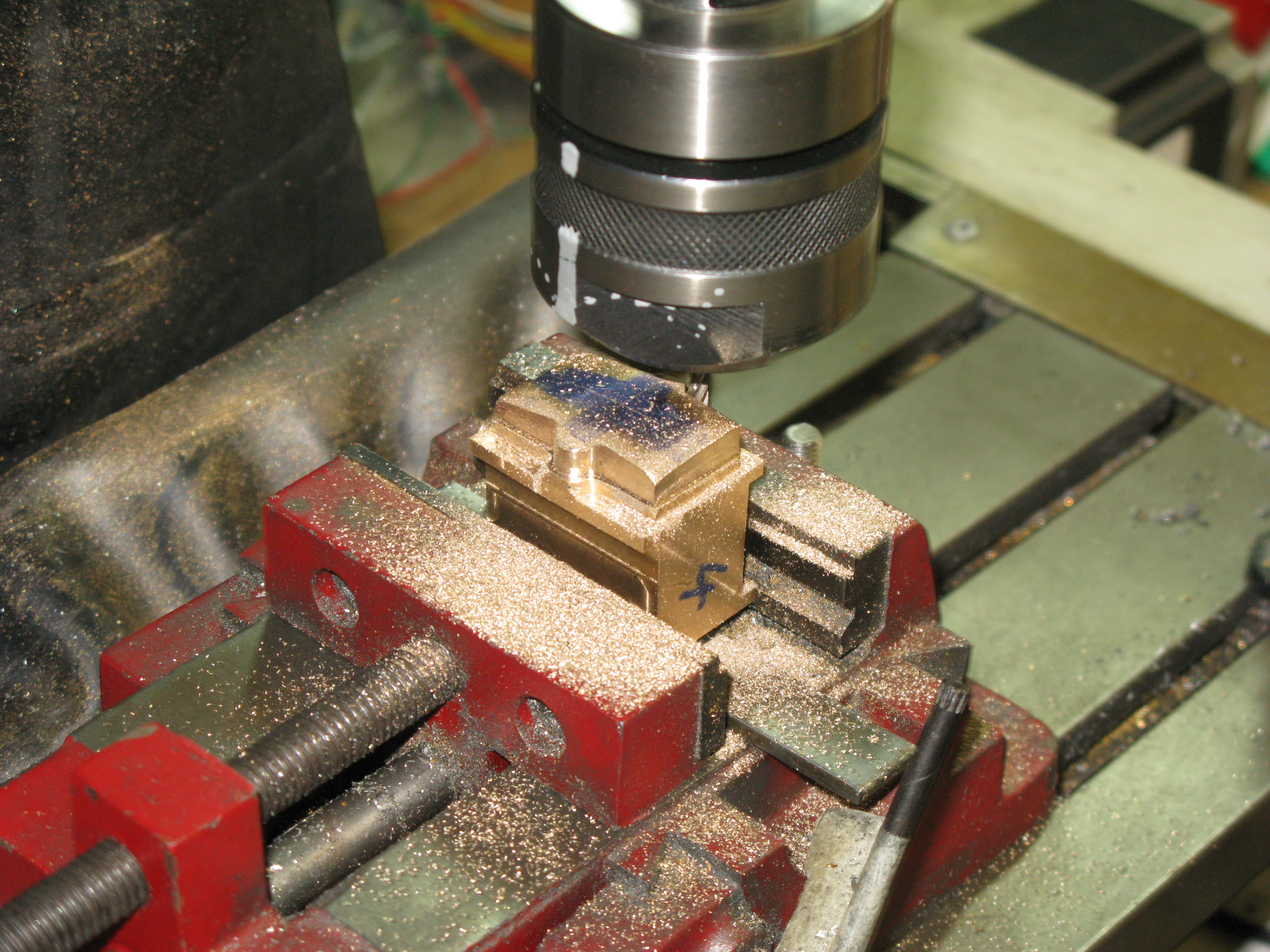
Before tackling that potential problem the blocks need to be machined. The first machining task is to make a flat reference side from which to work. I chose the axle box side as this was the easiest as the block could be clamped in the vice suported on a parallel, the block outer edge being on the parallel. This had the advantage of ensuring the machine face was parallel with outer edge. The blocks were machined in their cast pair configuration.
One of the problems of trying to grip shallow items high up in the vice jaws is the effect of the moving jaw tipping due to small amounts of play in the moving jaw. This means that trying to machine a second side square with the firest is almost impossible.
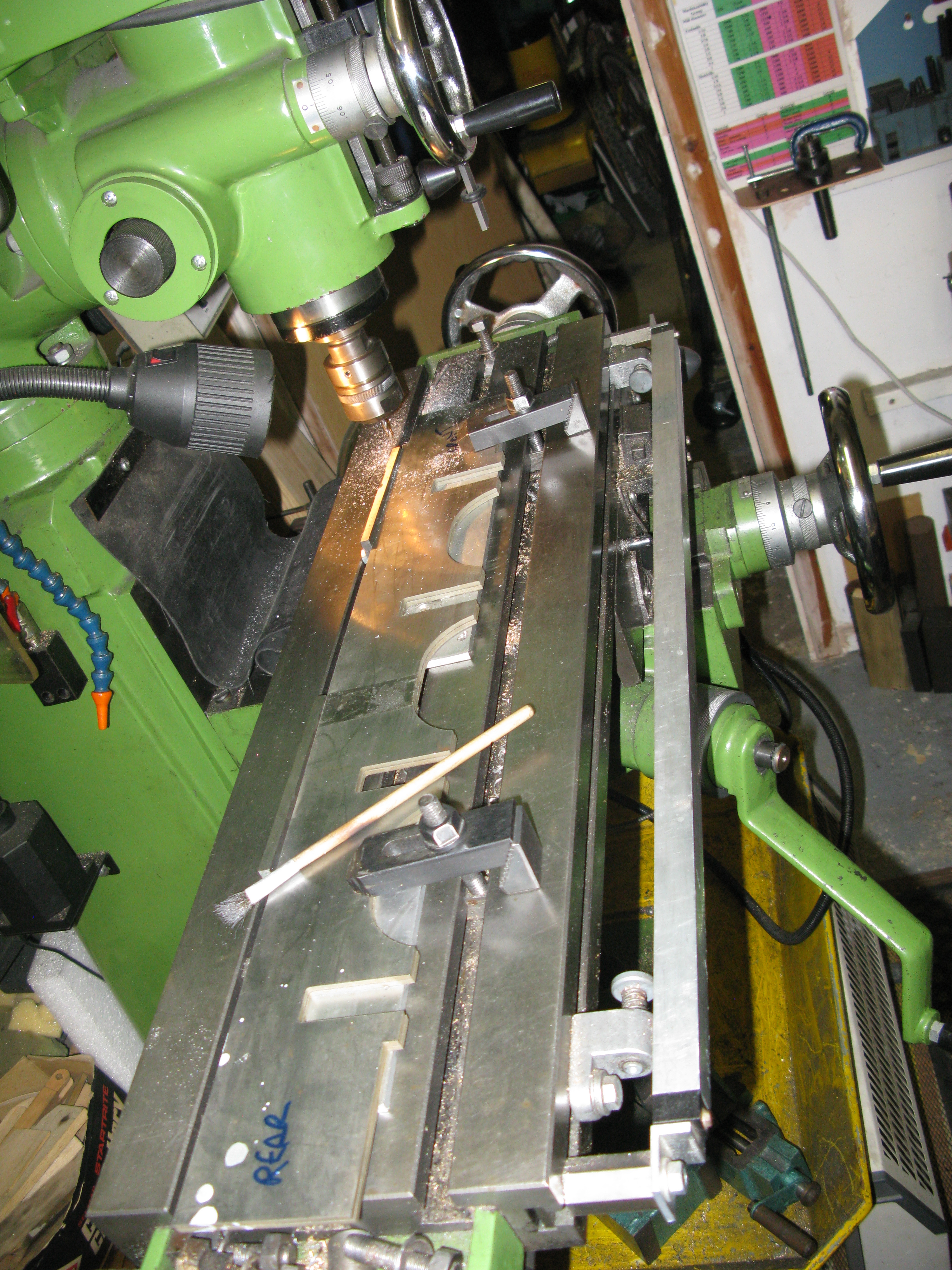
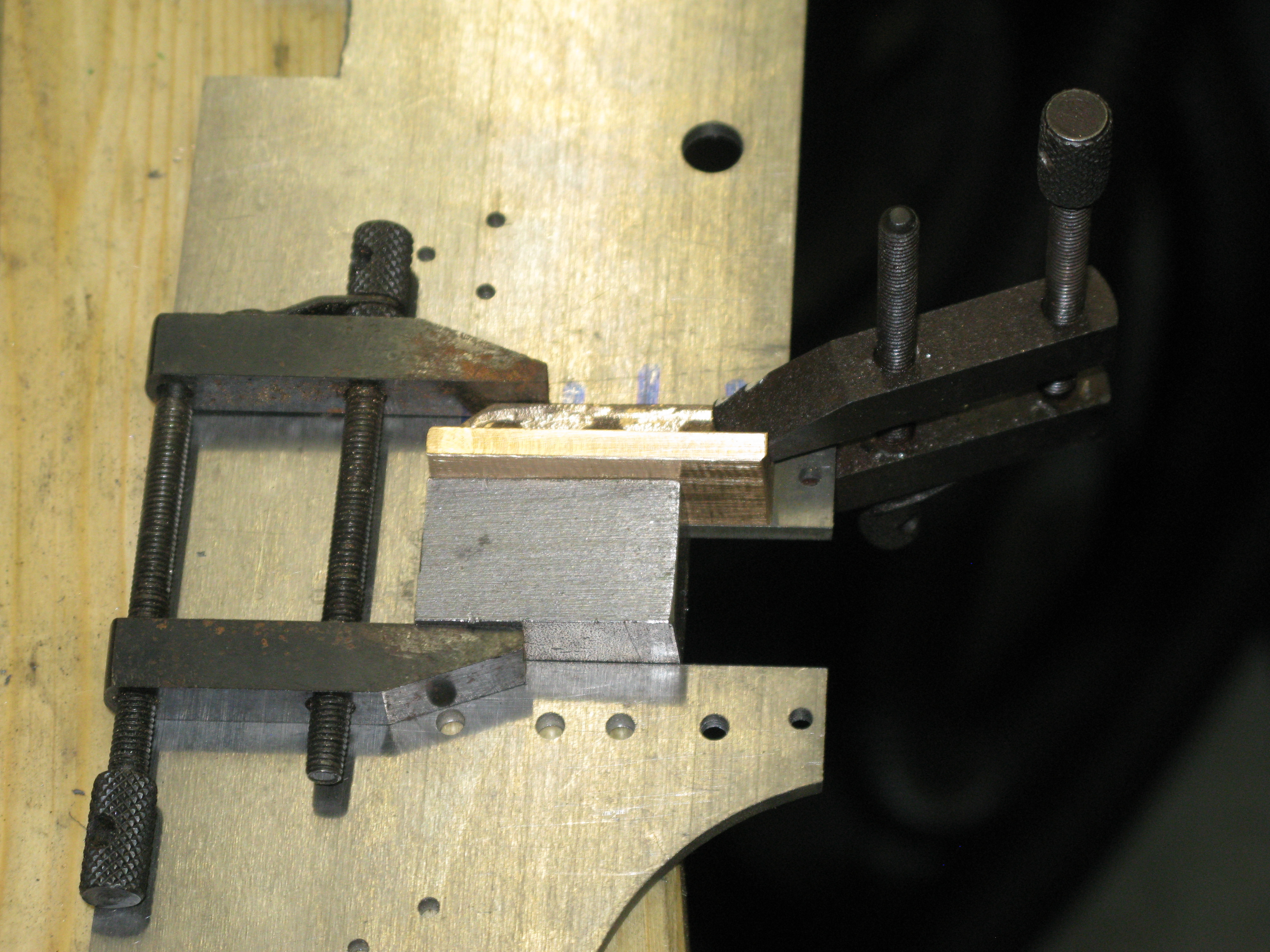
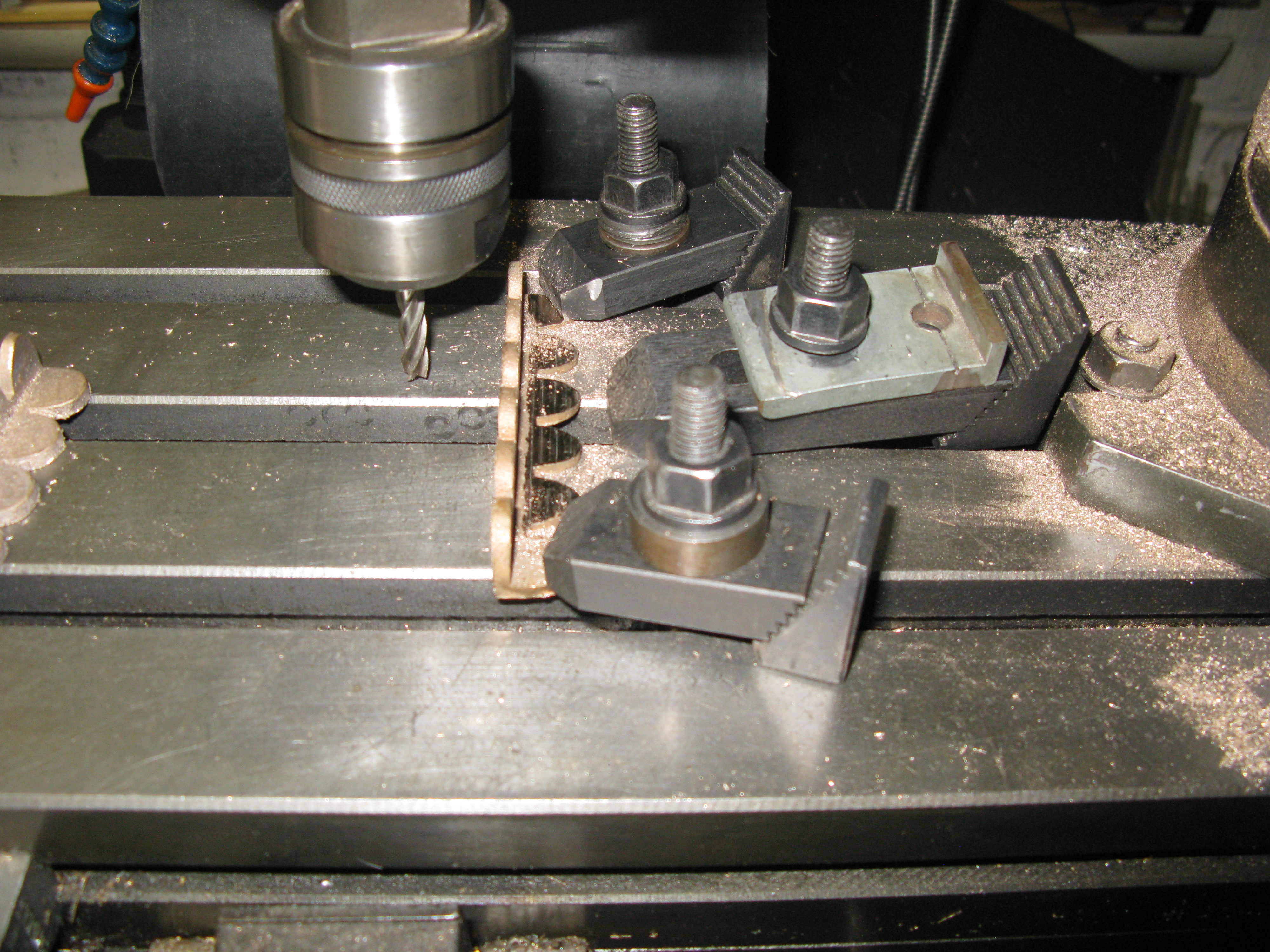
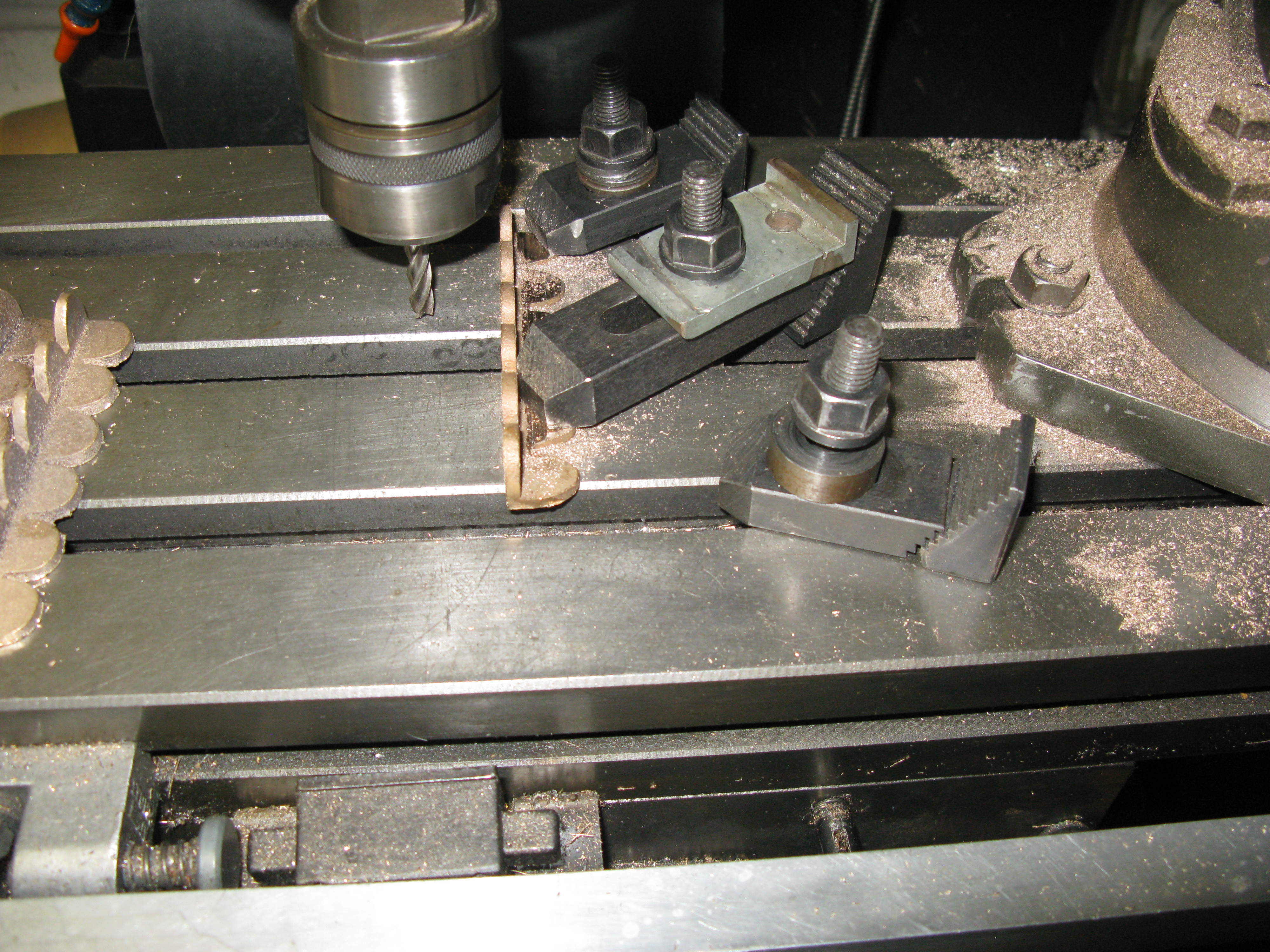
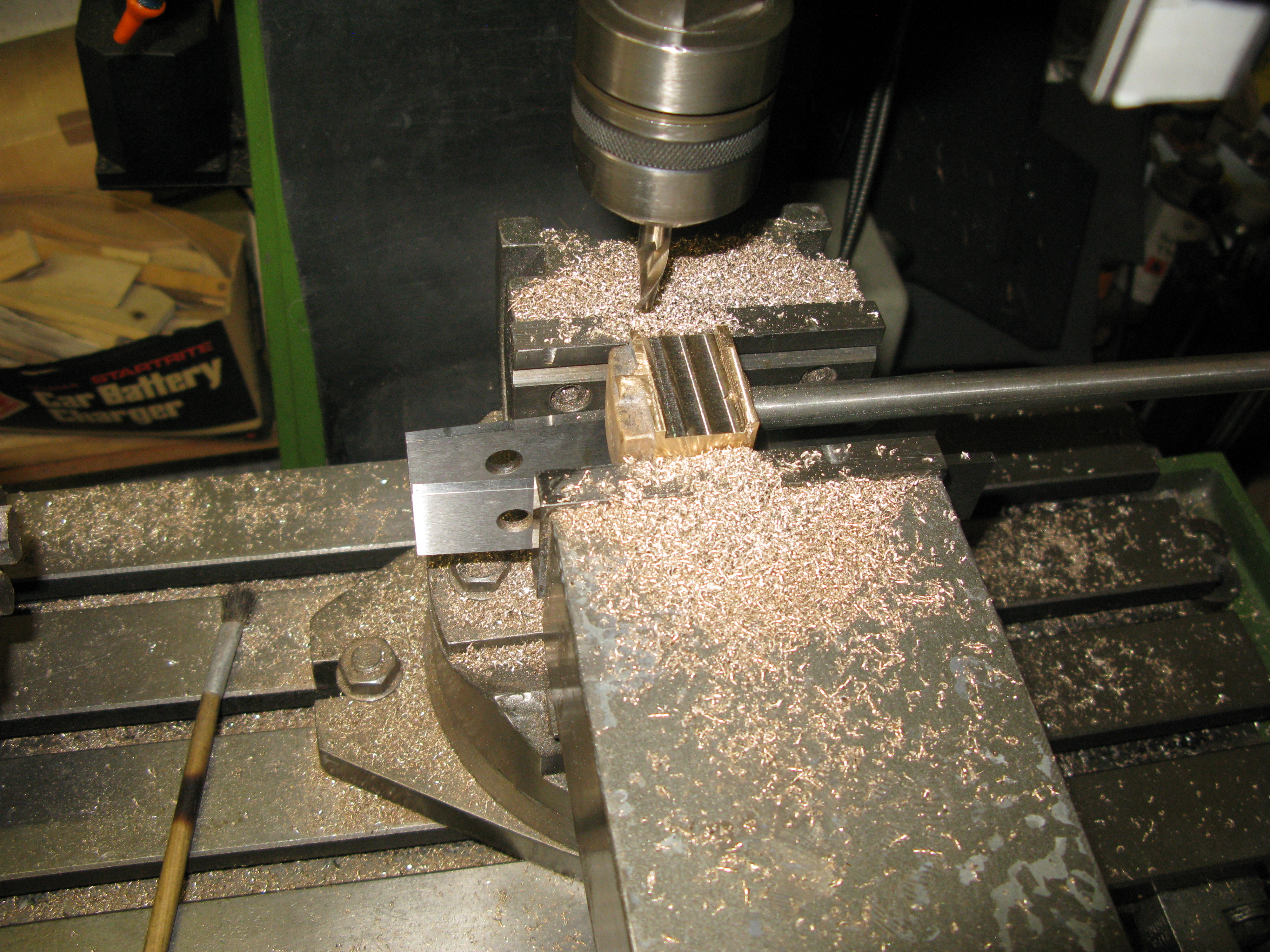
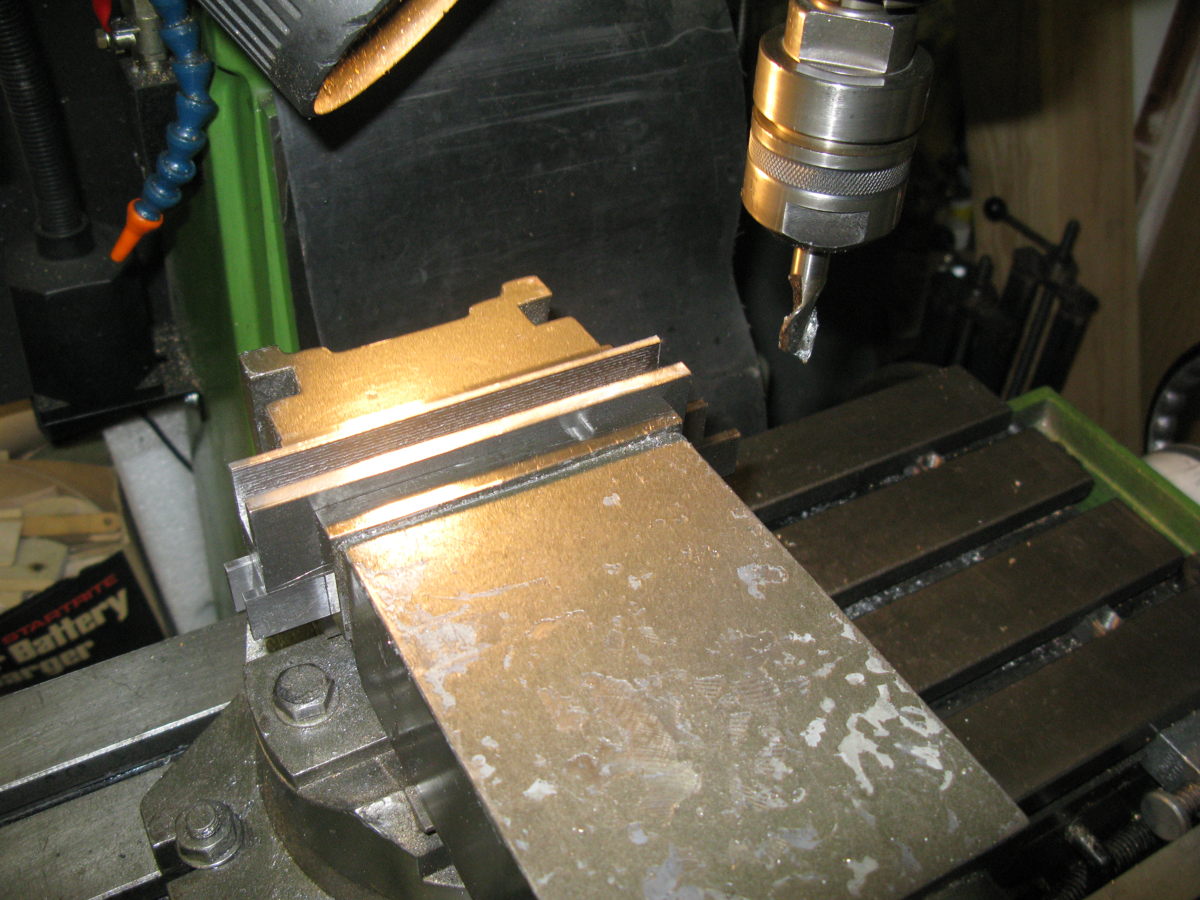
So having got a reference surface the next job was to machine the surface that bolts to the frame. The web that bolts to the frame is dimensioned at 5/32″ thick. To machine this face I chose to mount the hornblock on the mill bed on a parallel by the use of clamps. The machining would be done using the side of the milling cutter and would produce a square face.
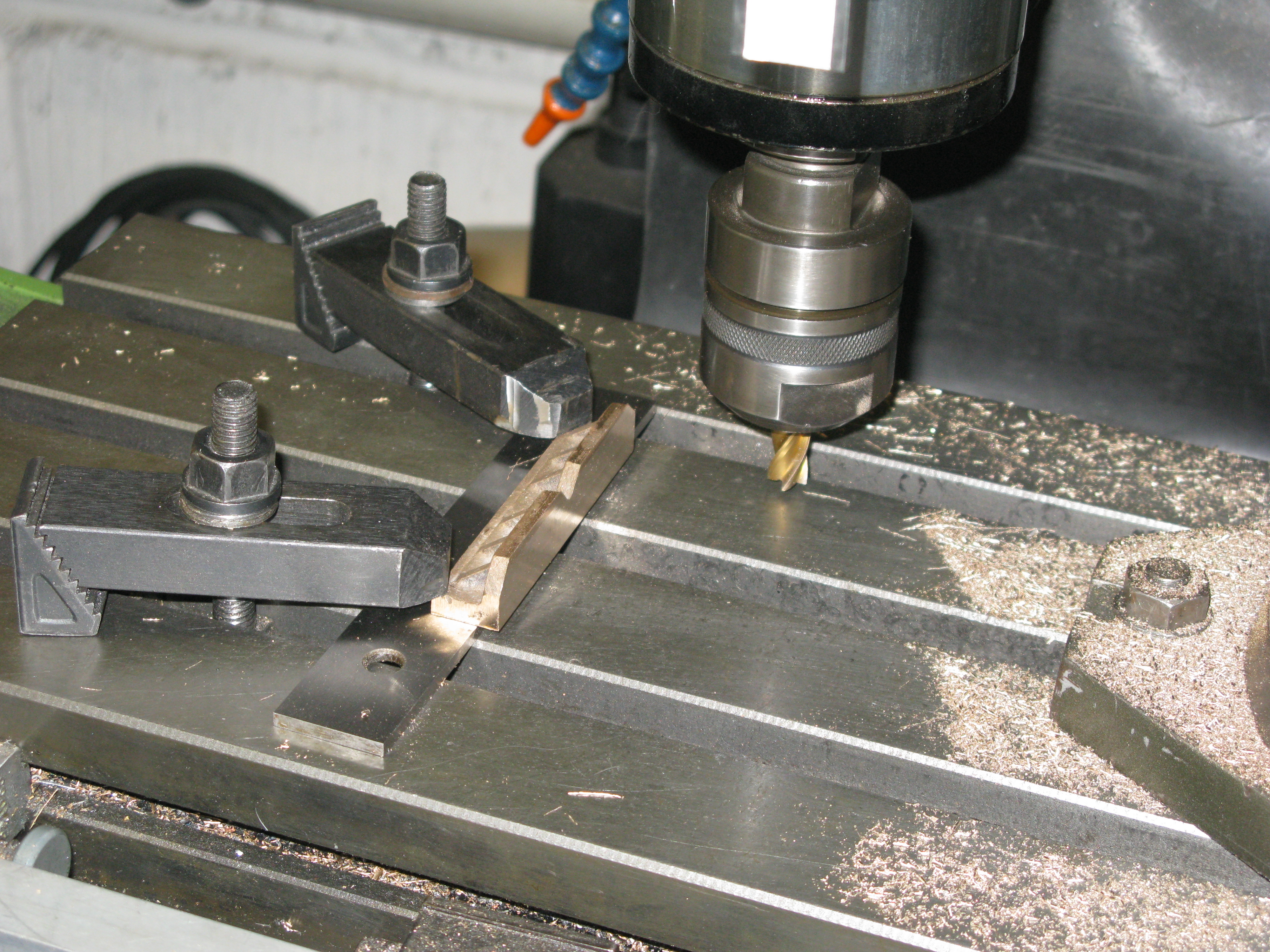
Whilst the clamping area was quite small is was very effective and the cut depths were very concervative to avoid loading the work piece too much and risking it moving. Also the cutter was new and sharp.
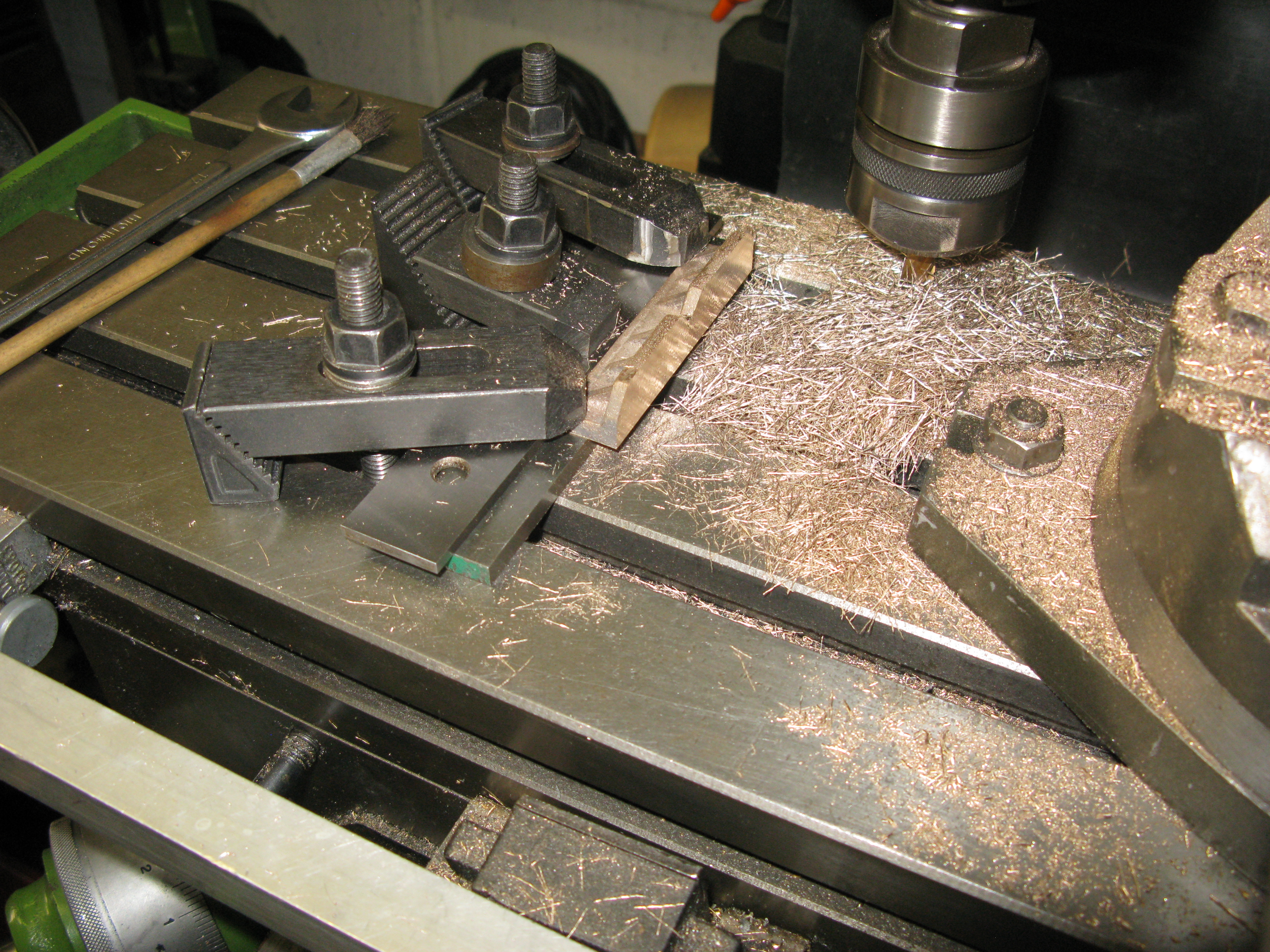
After taking the photo and machining the first hornblock I changed the set up by putting a fixed fence at right angles to the table against which the hornblocks where clamped. This made the setting up of the horn blocks quicker.
With the two faces machined the casting was sawn in two to produce the individual blocks. This showed up a minor problem in that the casting was not long enough to take the saw cut and end up with the correct length.
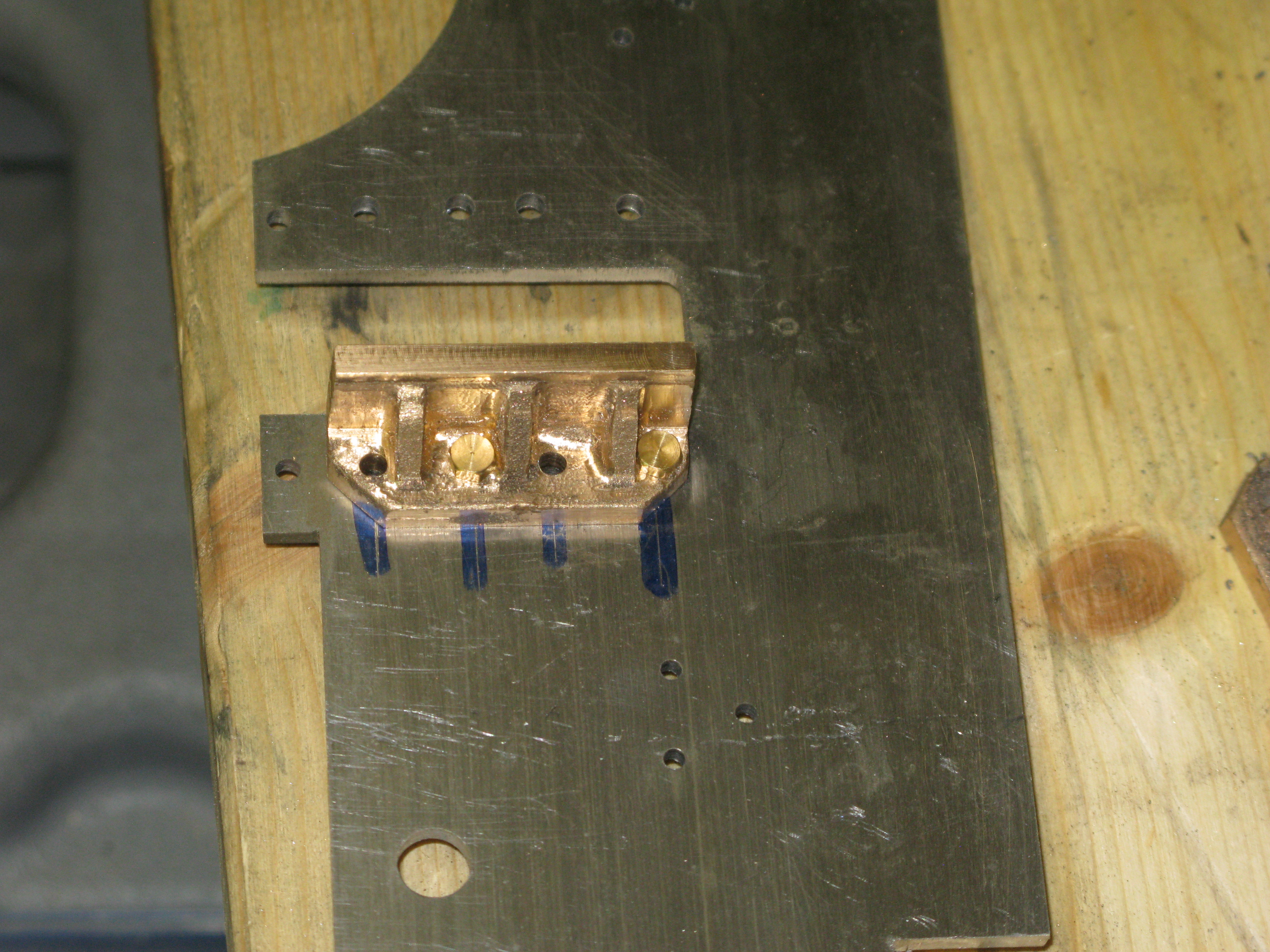
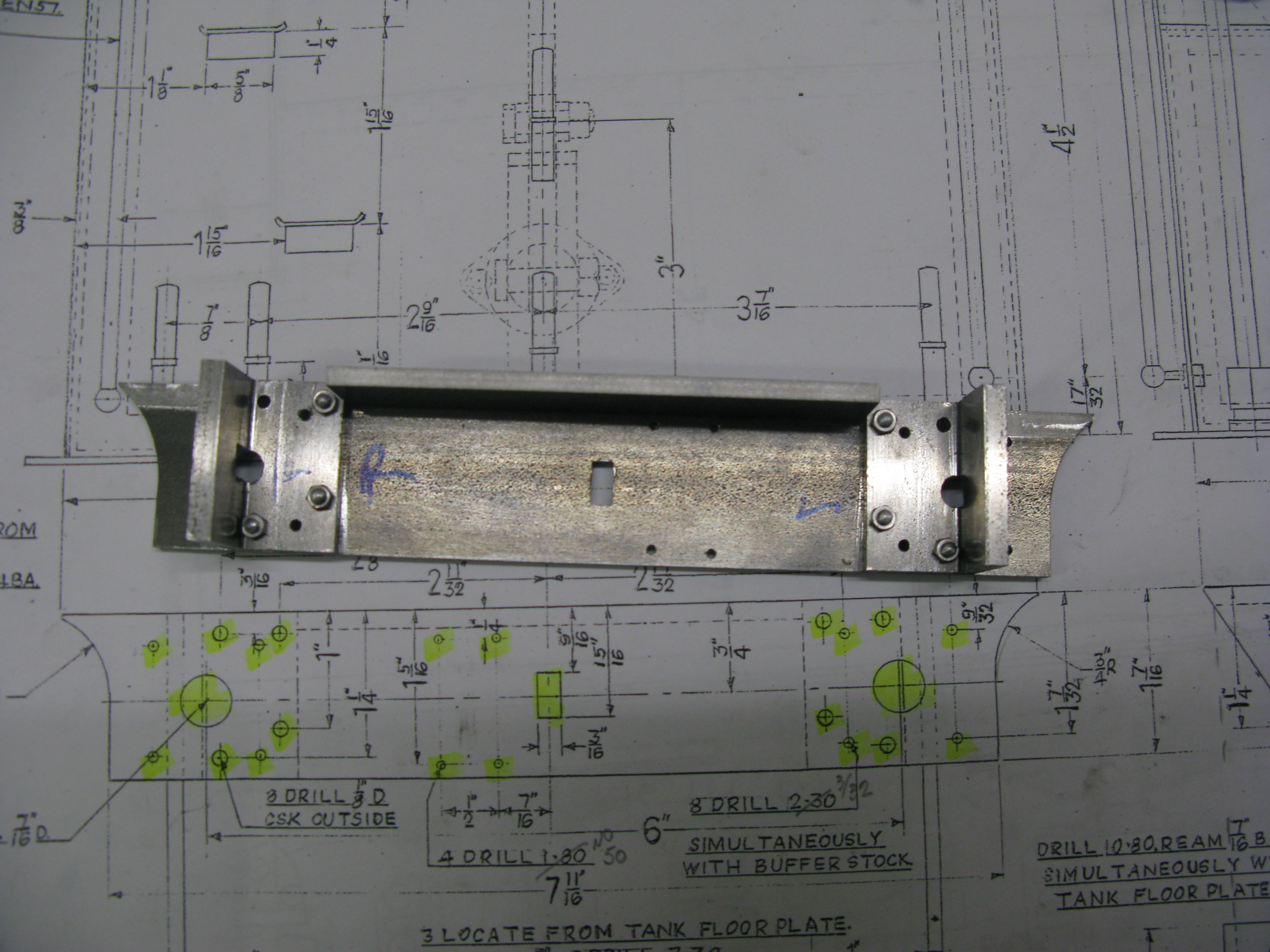
The next problem to be identified was the alignment of the drilled holes in the frames with the gaps between the webs on the casting.

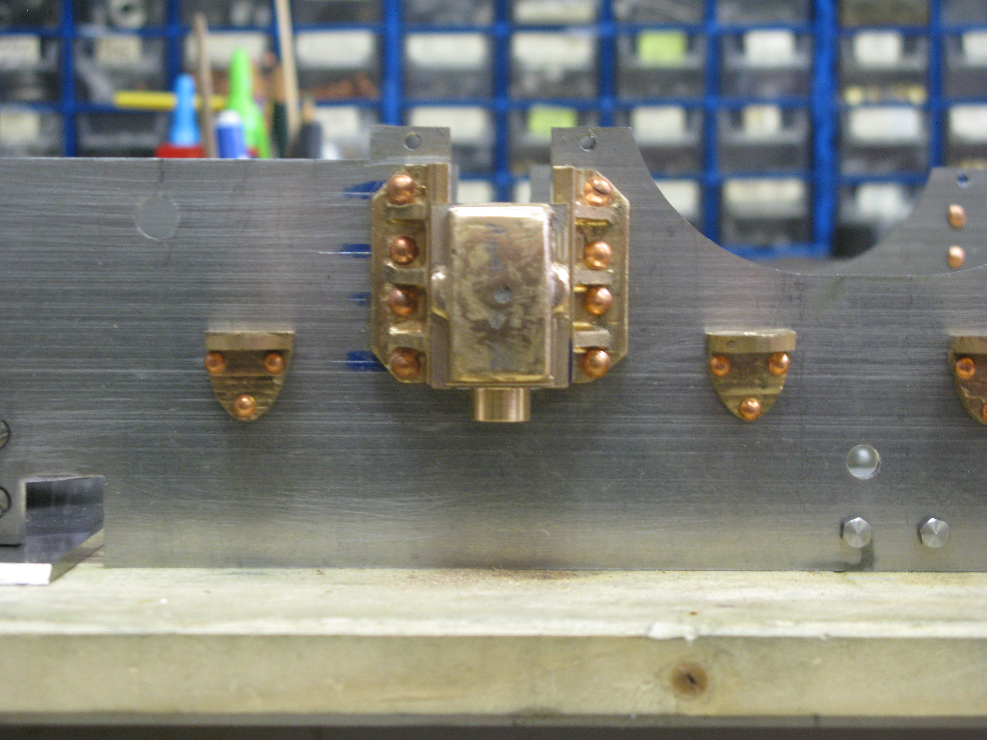
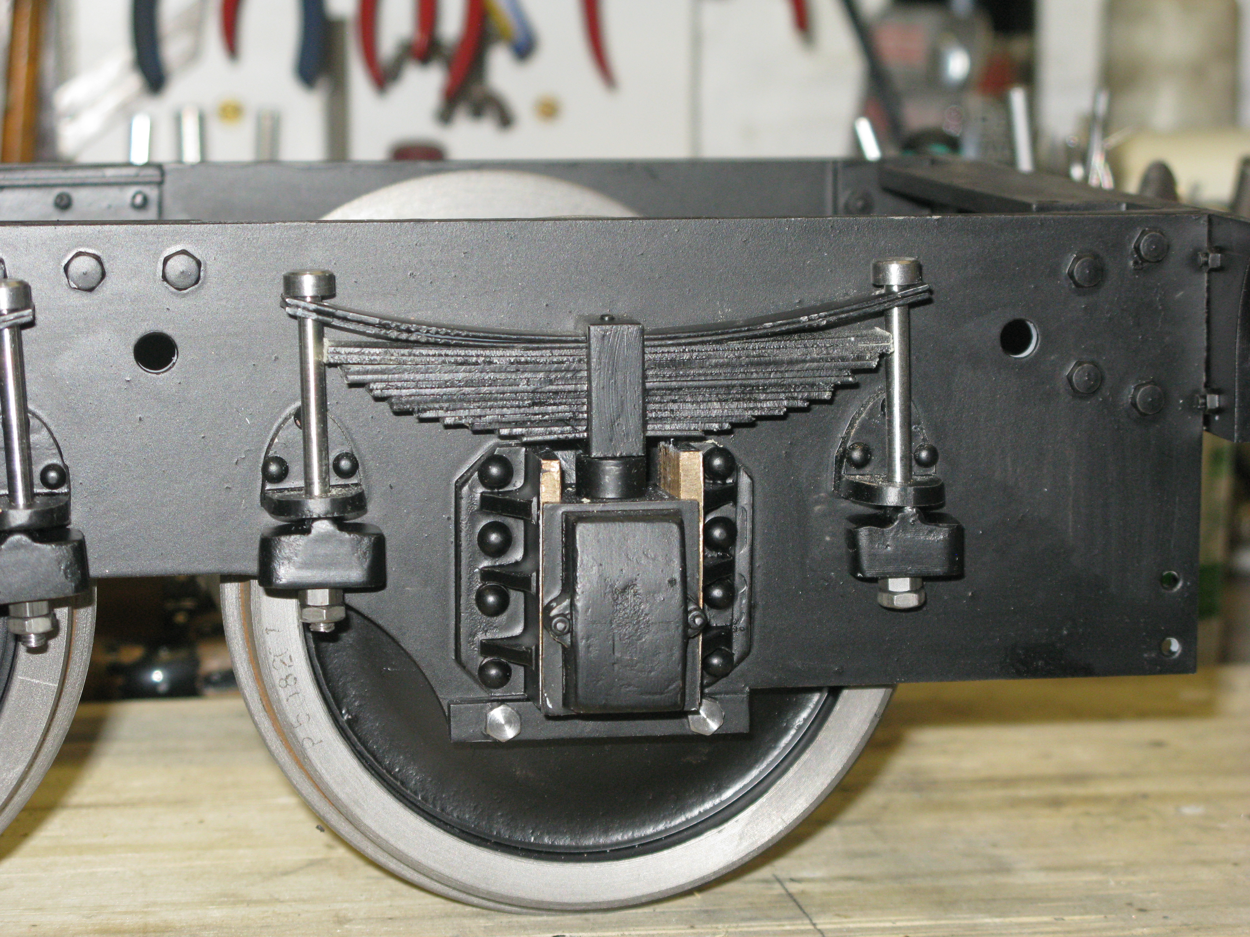
With the casting set at the correct height from the top of the frame it can be seen in the photo above that the centre lines of the holes do not fit nicely with the gaps beteen the webs.
The horn blocks are riveted to the frames with 1/8″ RH rivets and there is not enough room for the heads in every case. In order to find out exactly where the holes would come in rlation to the webs I jig drilled the holes from the frame.
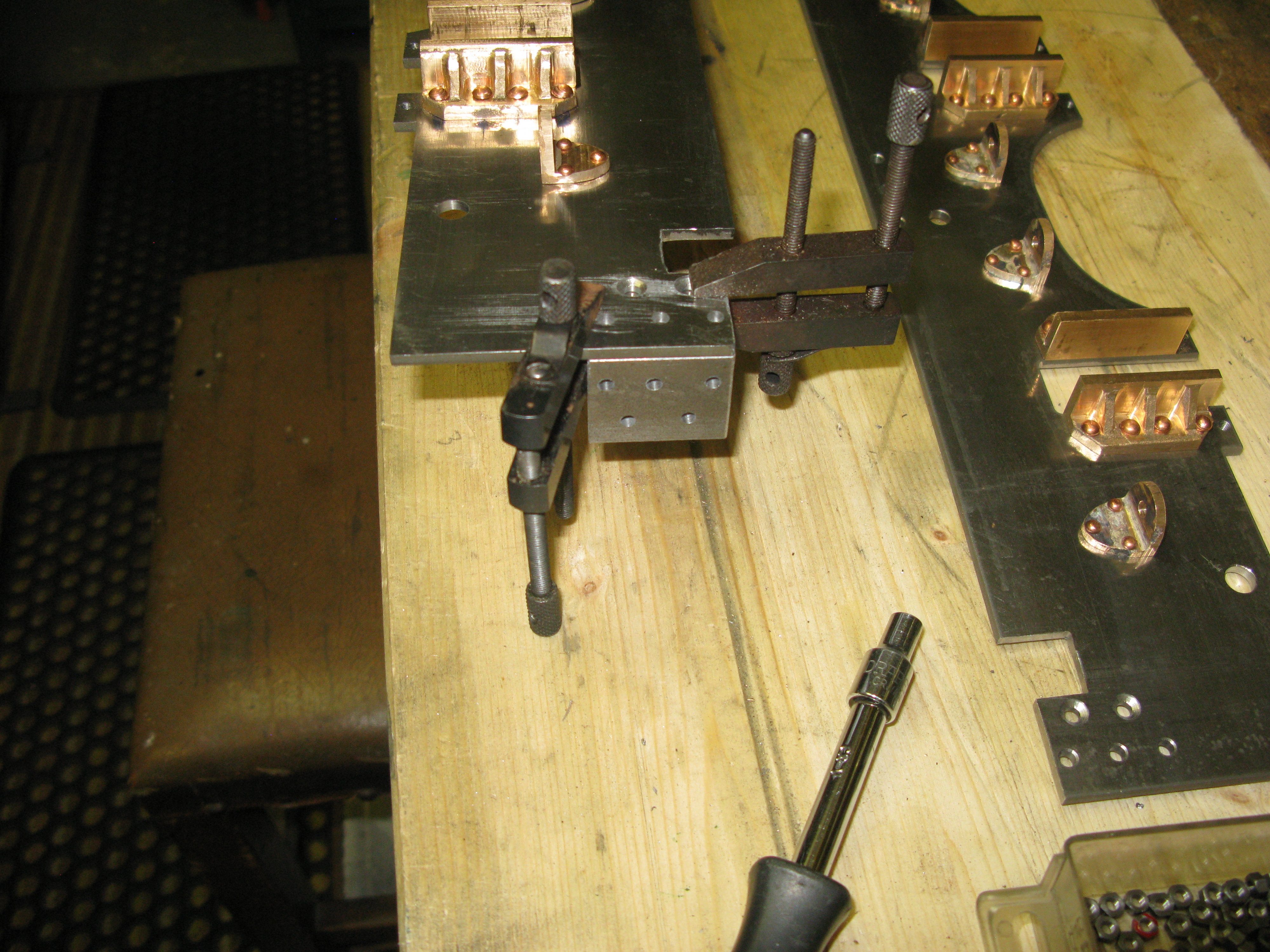
To do this I used a 3/4″ spacing block that fits into the frame and a couple of jewellers clamps to hold the block in position. Withe holes drilled it was clear that the webs would have to be machined to allow the rivets to fit.
Block in place with temporary bolts.

The next difficulty was that the head of the rivet snap does not fit cleanly on the rivet head as there is insufficient clearance despit grinding the snap head down as far as I dare without weakening the edges. The net result is the rivet heads are not nice but disfigured.
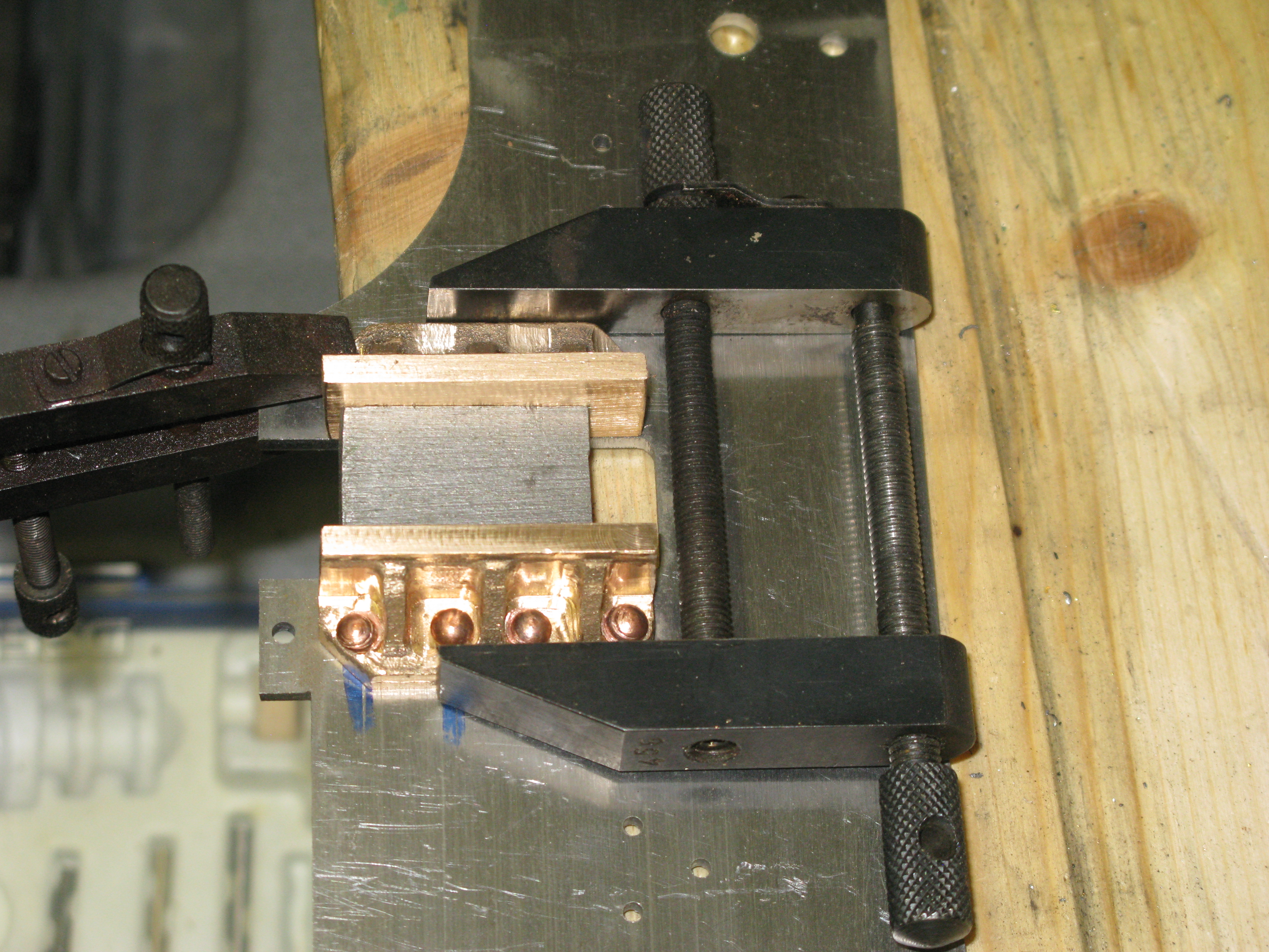
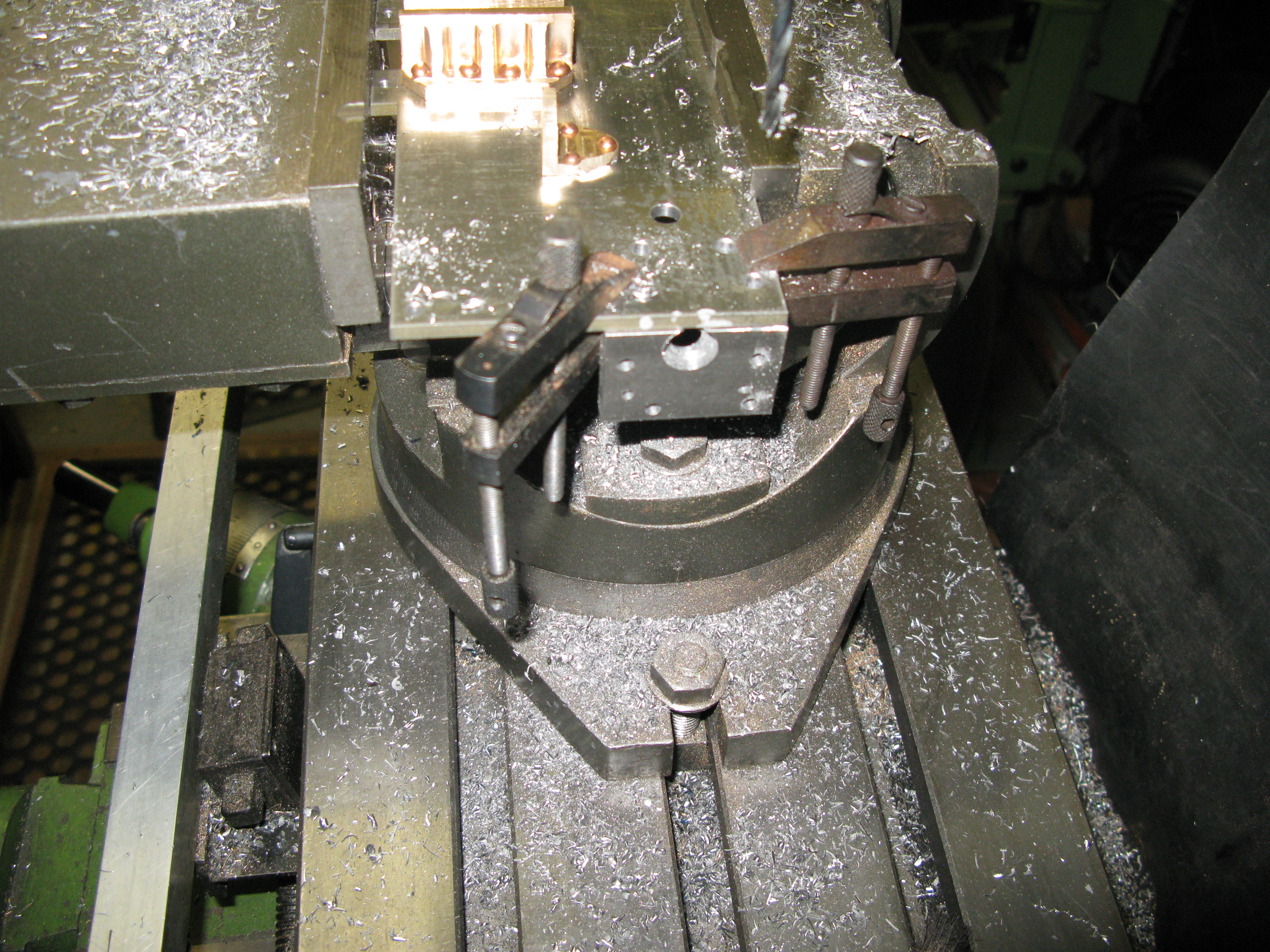
To get the other block in place and ensure it was parallel I used the spacer again and clamped it all together to jig drill the holes.
So that was the first axle box horn blocks done and the method of doing it was OK but the end result in respect of rivet head finish leaves a lot to be desired. I now have to think about the other 15 to be done!

One and a half frames done, but I am really struggling with fitting the horn blocks due to the poor castings plust the mis match of dimensioned holes with the casting ribs. I know not which is to be blamed, but I suspect the casting and possibly the pattern maker. Jig drilling the horn blocks from the frames alway gets one and sometimes two holes right up against a rib and invariable when that happens the drill breaks on break through as it gets pushed over and jams. I have gone through half a dozen 1/8″ drills so far!
Having managed to fit all the horn blocks I turn my attention to the spring hangers.
Here I find another minefield as the hangers come as a cast stick of six and the castings are quite frankly close on rubbish. I will just have to get the best I can out of them and hopefully they will all be of a similar size and shape.
I machined a reference face by holding the stick in the mill vice first.
The stich was then turned over to mill the other face flat.
Having checked that the two faces were at 90 degrees to each other the inside faces were milled by clamping the stick to the mill table with a clamp at either end then adding a clamp in the centre and removing and end clamp to complete the cutting.
This process gave me the required thickness of the hanger.
Tyhe next task was drilling the holes. This is where the casting problems really showed up as the centre of a hanger as determined by its base width was not necessarily the centre compared to the apex. So a lot of juggling around to get the best compromise possible was necessary.
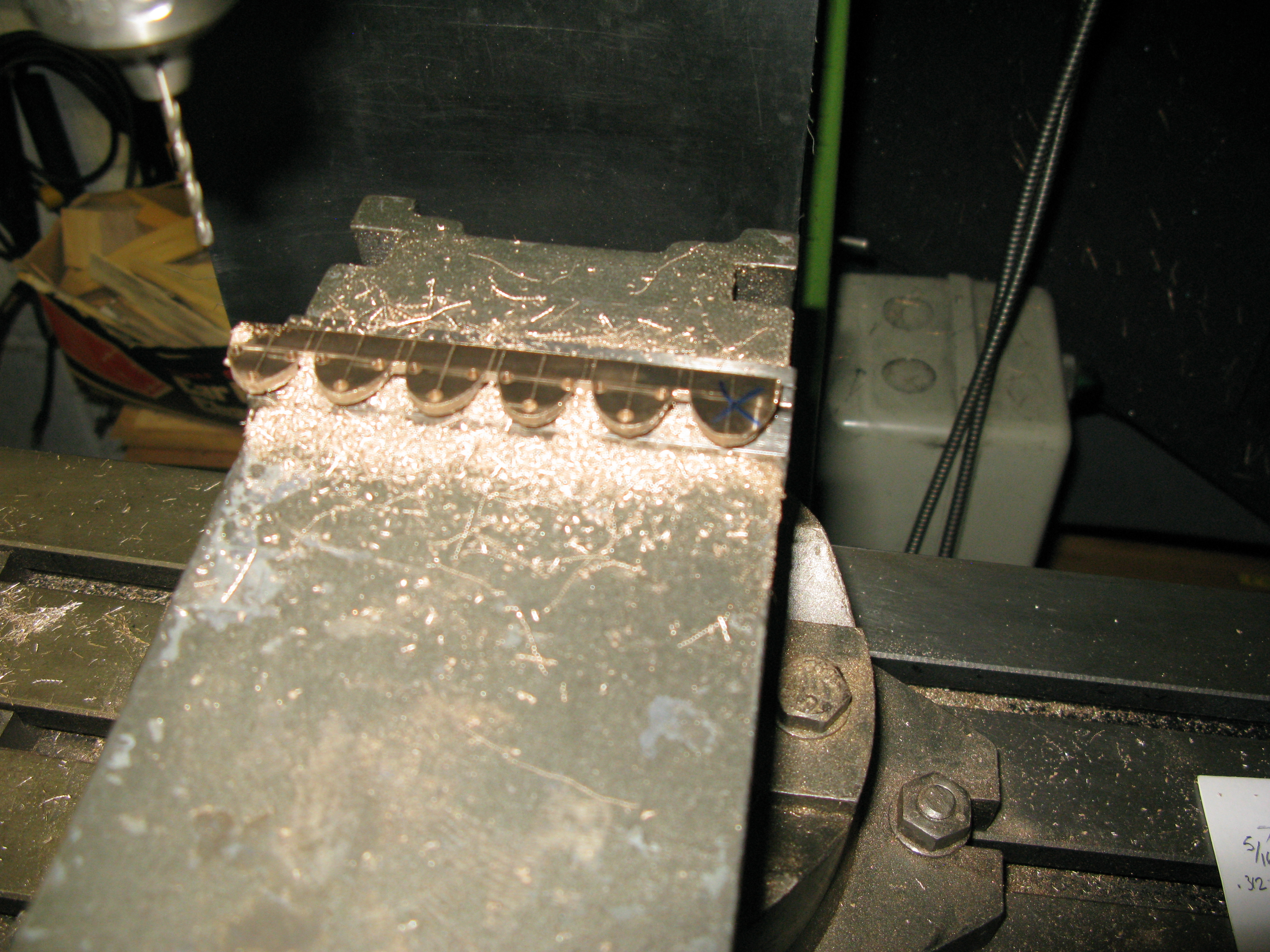
As a consequence some of the holes are nearer the edges than others.
However finally 16 were produced and fitting them is underway.
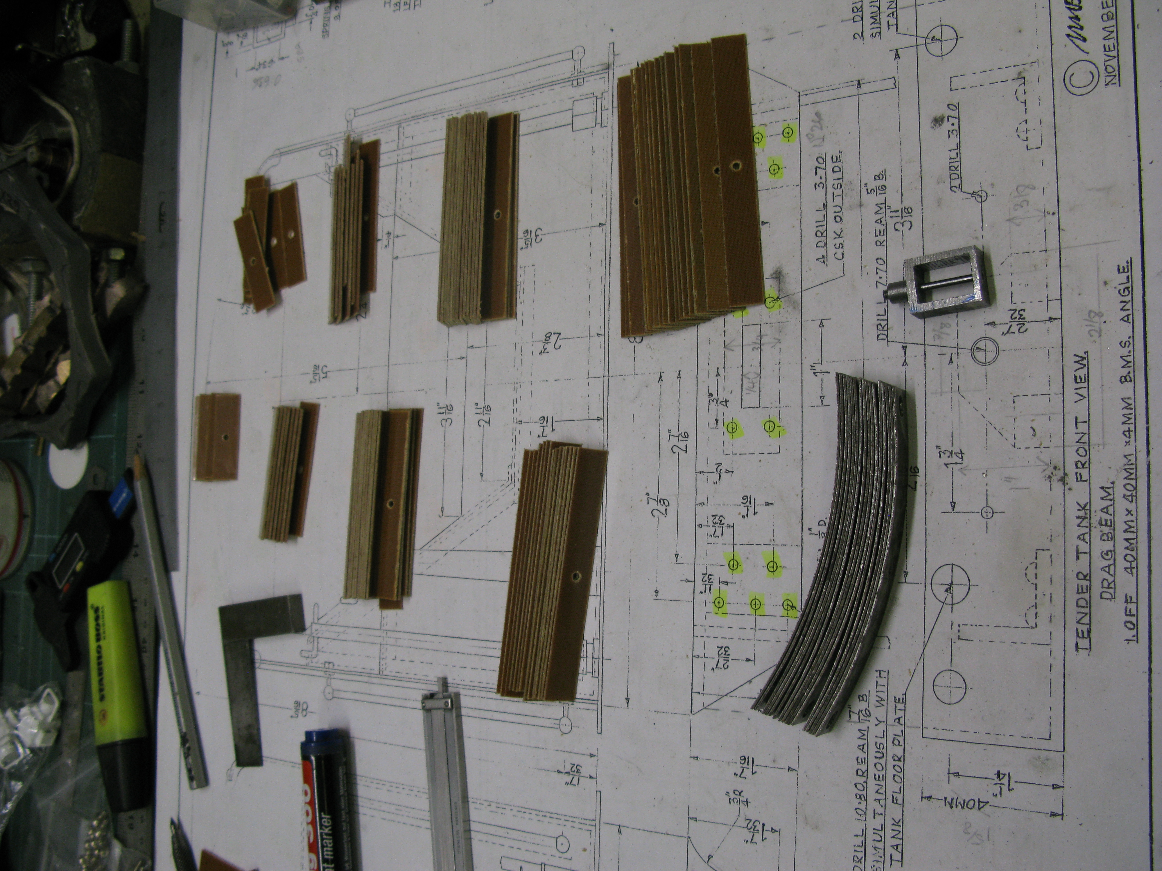
Front and rear beams
The front and rear beams are made from 40mm x 40mm x 4mm bright steel angle. This has to be machined down to size for the depth of the front beam and the ends cut at an angle. Once done it is then drilled and the slot for the drag bar milled out.

There are holes to be drilled in the top of the beam but these will be done when the tender floor plate is in position.
The beams are held in place by BMS angle 20mm x 20mm x4mm that bolt to the frames. When I ordered the material for the beams I failed to check the delivered items and when I came to make the angle brackets I found they were 5mm thick. This gave me a minor problem later on when drilling the holes as the outer holes on the beam now came very close to the inside edge of the bracket meaning that the fixing was going to be a problem.
In making the brakets the drawing calls for four, two for the front and two for the rear beam. However the front and rear beam fixing holes on the frame are not the same so just as well I noted that before drilling them.
The brackets were jig drilled from the frames and also jig drilled from the beams.
The fixing of the brackets to the front beam is shown as a countersunk rivet. As mentioned above with the holes coming close to the inner edge of the bracket a rivet snap could not be used, but there was just enough room for a 5 BA reduced nut with one face thinned so I decided to use 5 BA c/s screws as the fixing.
The fixing to the frame is 5 of 4BA into tapped holes of the bracket. Two of the fixings are c/s the other three hex headed.
The temporary fitted front drag beam
The rear buffer beam is attached to the frames in a similar manner to the front drag beam. However the holes are different for fixing the angle bracket to the frame.
Jig drilling the angle bracket fixing holes
Here the drawing shows the problem of the foul of the bracket/frame and buffer boss and rod

Angle brackets temporary in place – note the recess for the bbuffer stock
The fixing of the buffer beam to the angle brackets is by 5BA c/s screws. Now a problem arises.
The distance between the inside edge of the frames is 6 3/8″. The distance between the centre lines of the bufferes is 6″. The buffer stock is recessed into the buffer beam and angle bracket by a 7/16″ dia boss and the buffer rod is 1/4″ dia. This results in the boss fouling the frame and there being no room for a retaining nut on the buffer rod. This means the angle bracket has to be relieved to give room for a nut with one side machined very thin to clear the frame.

The relief machined in the angle bracket to accept the buffer rod nut
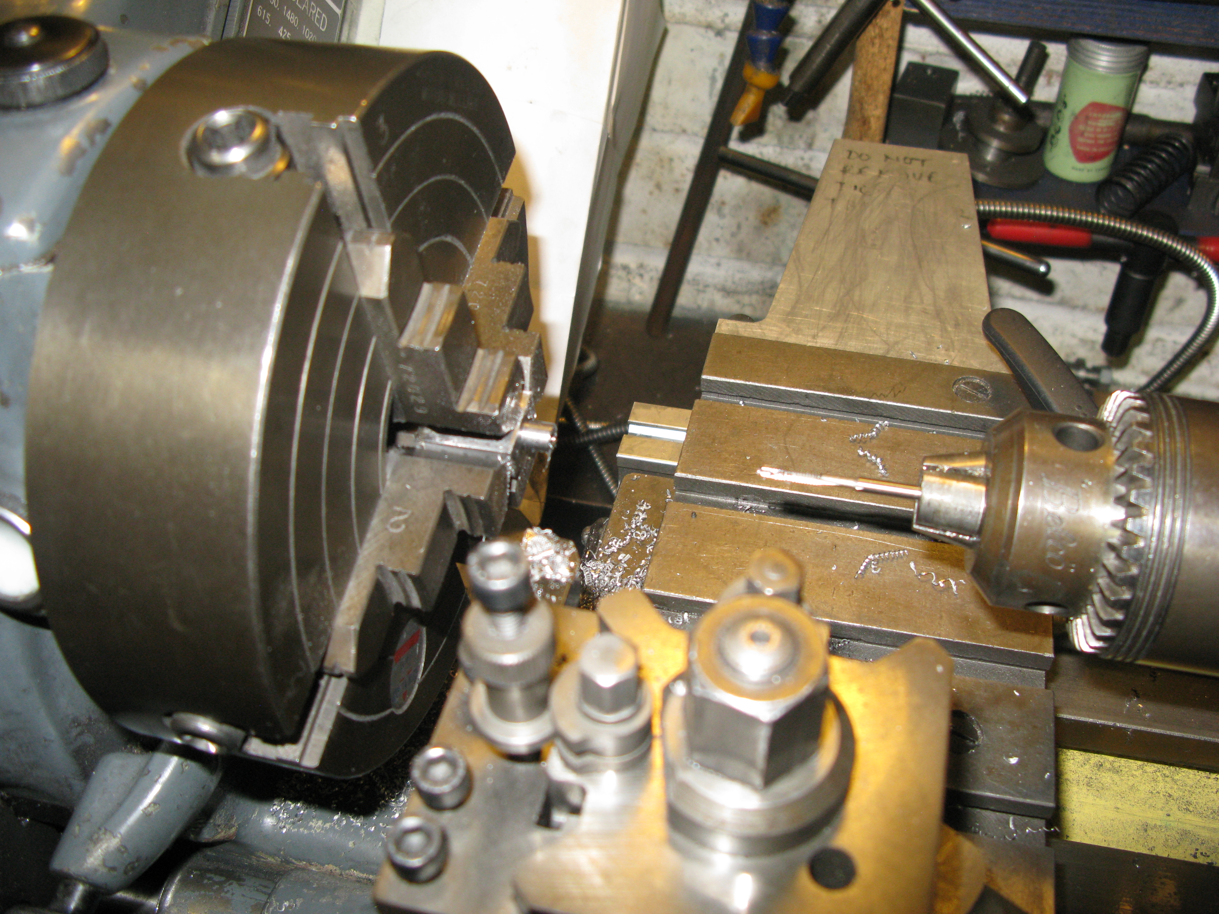
The buffer stock is machine from 1 1/4″ square BMS. It is first reduced to the overall measurement of 1 3/16″ square then using a self centering four jaw chuck turned down to the profile and drilled and bored out for the buffer.
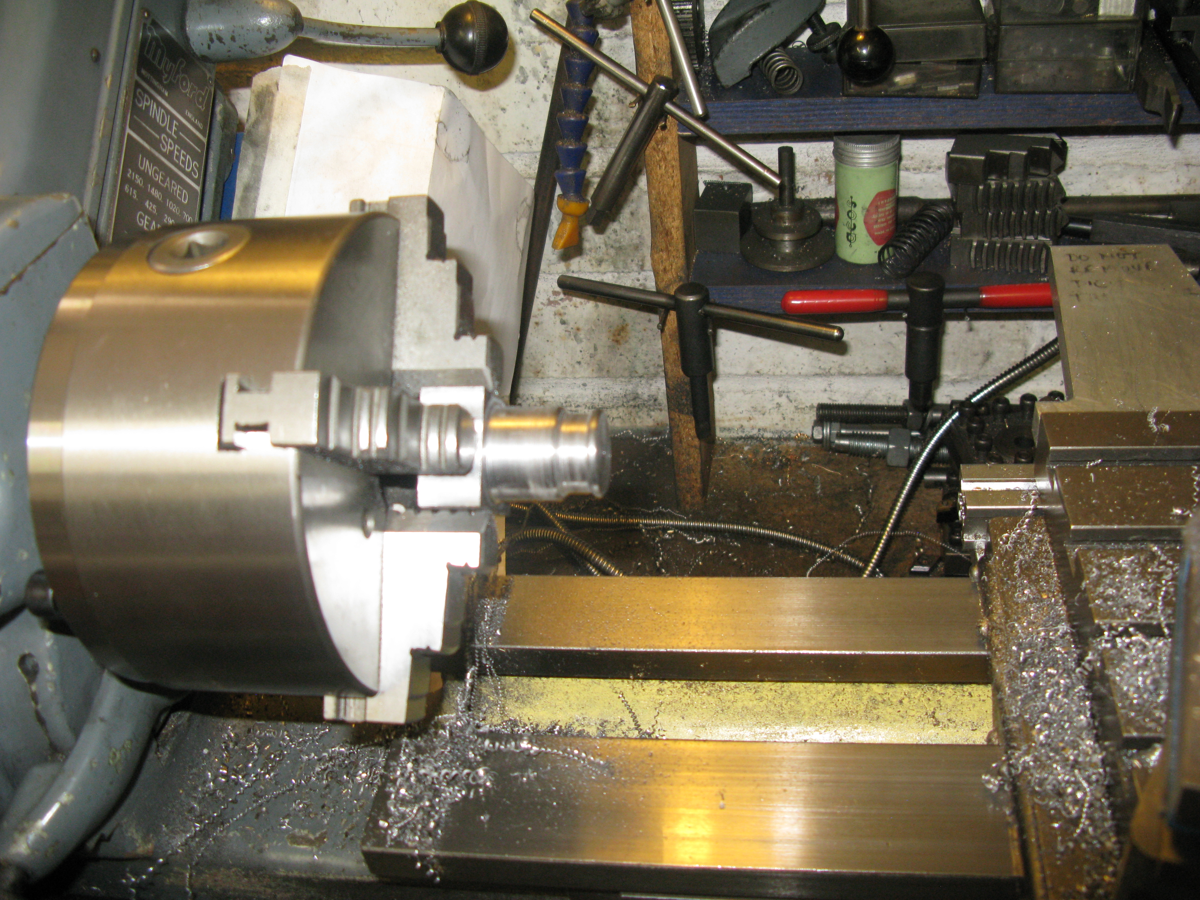
The work is then turned around in the chuck to machine the boss.
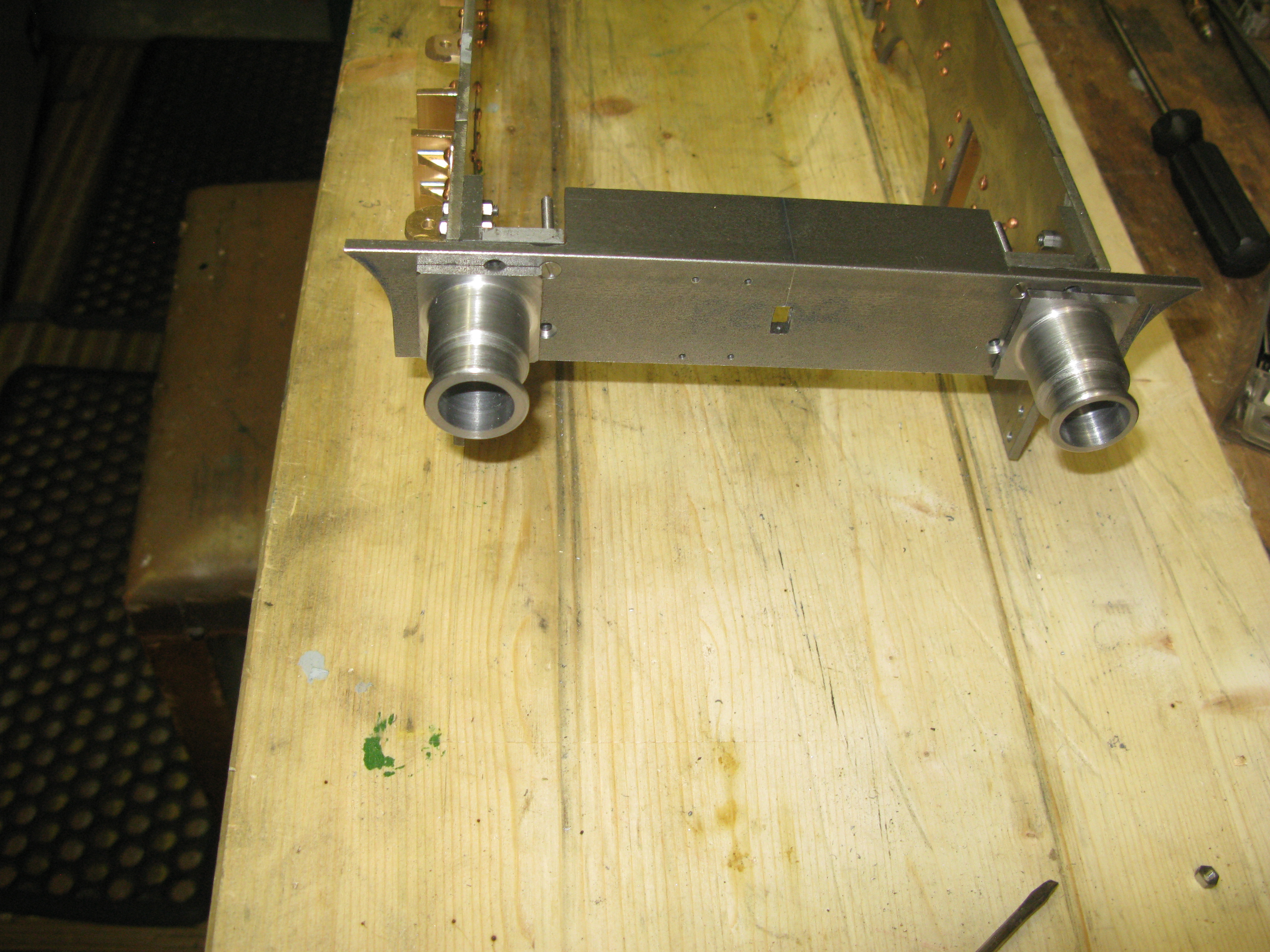
To get the buffer stock to fit in the recess of the buffer beam a flat has to be filed on the boss to coincide with the inner edge of the frame. The buffer stock is jig drilled from the buffer beam for 8 BA fixing screws.
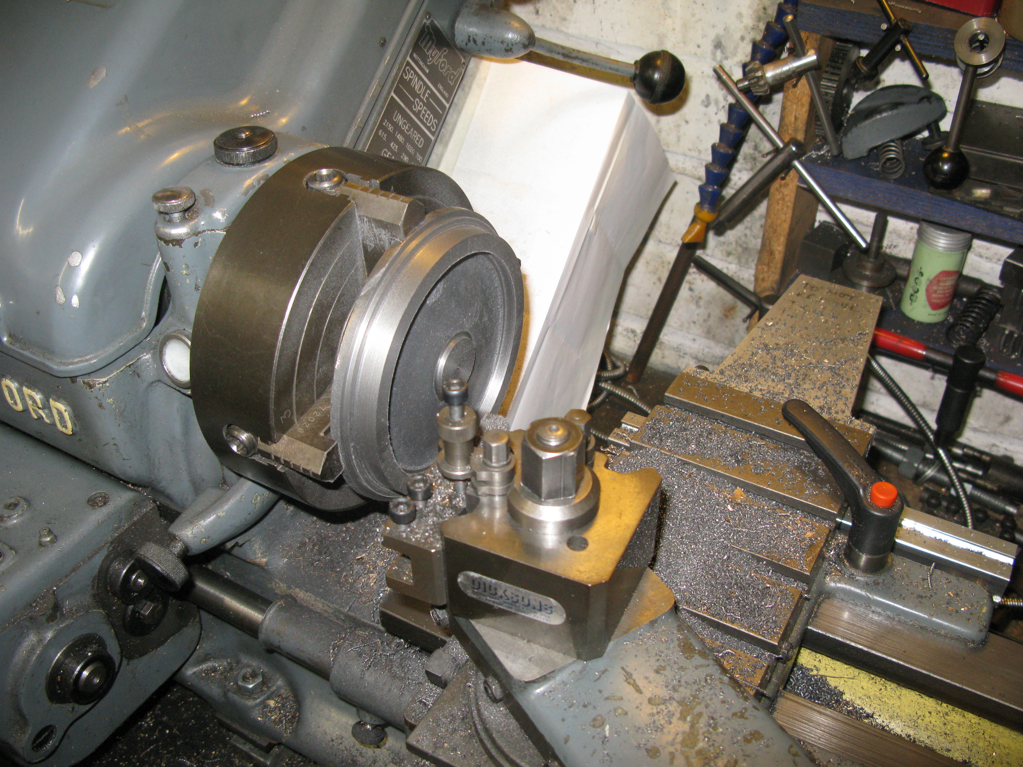
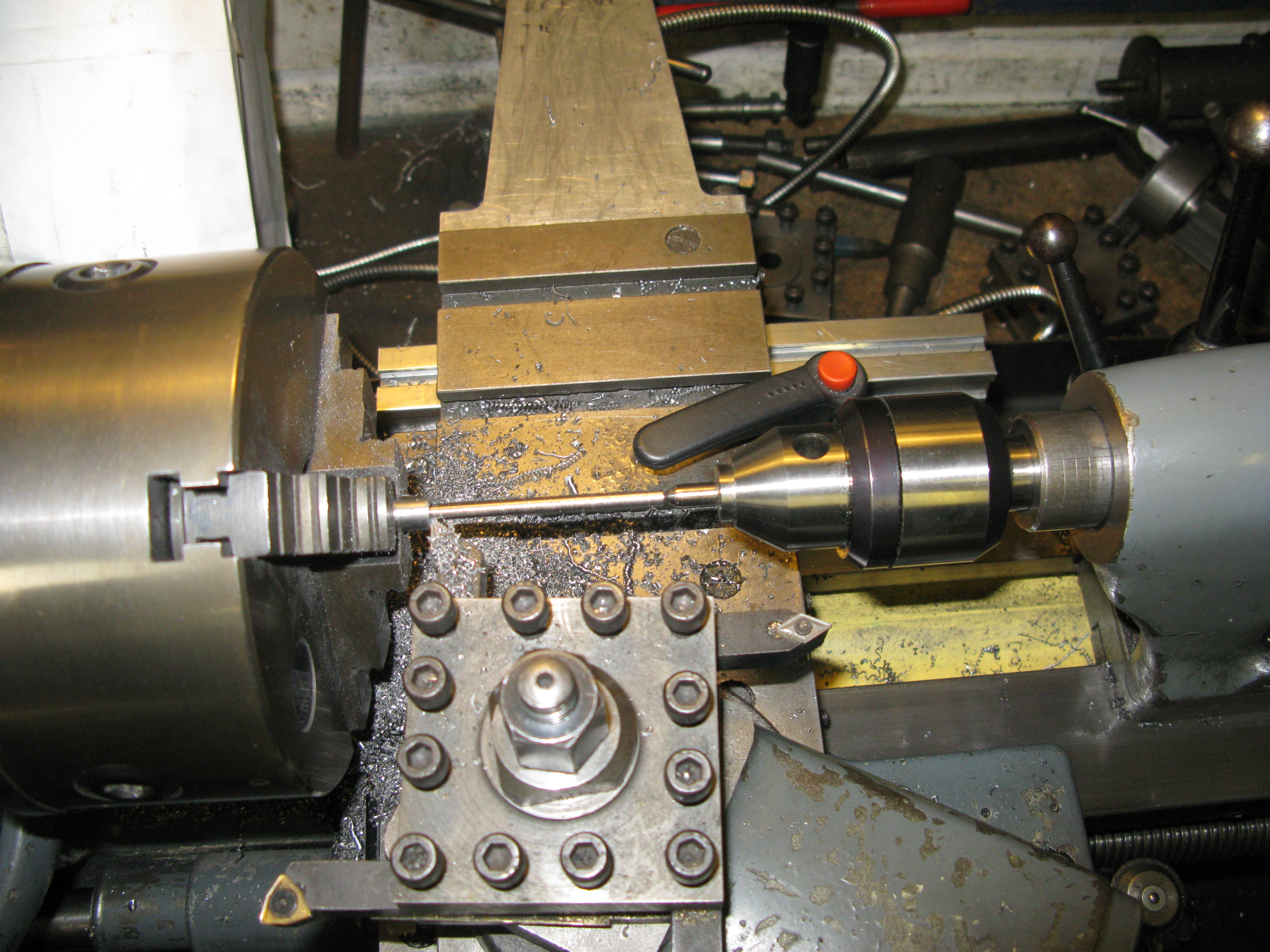
The buffers are the same as the loco front buffers, 1 7/16″ OD with a 1/2″ stub to slide into the head stock. The first task is to turn down the stock material to give the 1/2″ by 11/16″ stub. This is then drilled and tapped 1/4″ x32 ME by 1/2″ deep. It is then turned around in the chuck and the rear of the buffer turned at 10 degrees and the out side diameter finished to size.
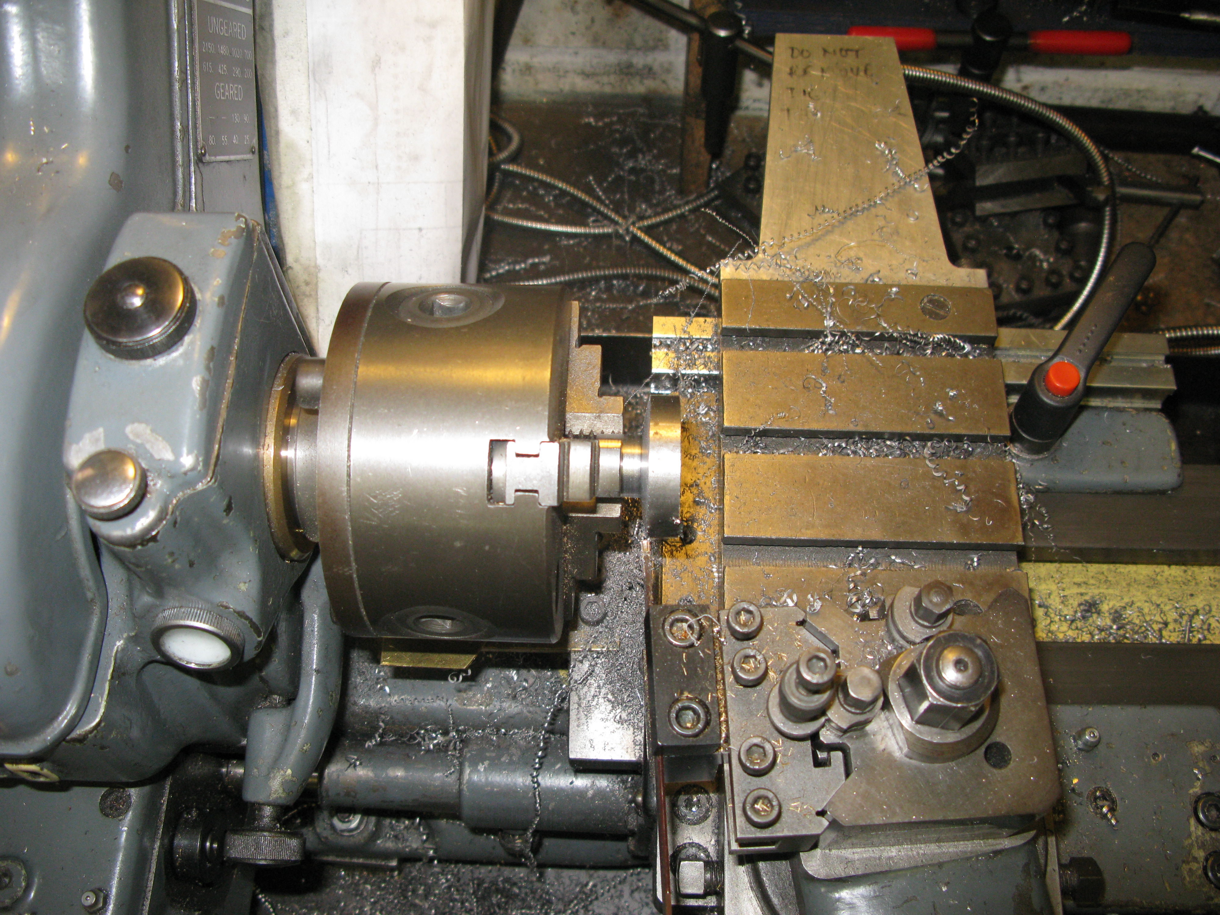 Machining the 10 degree rear taper.
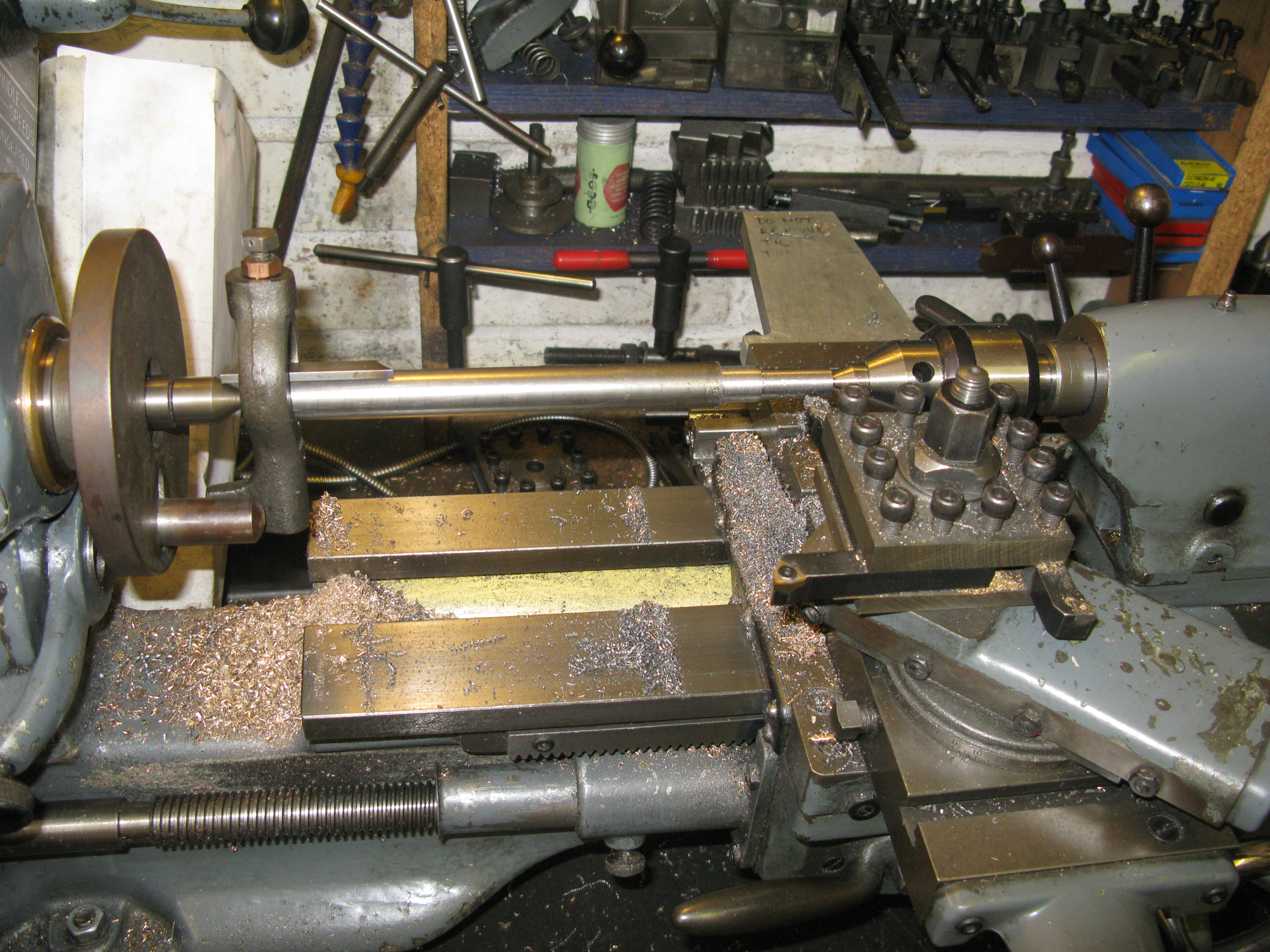
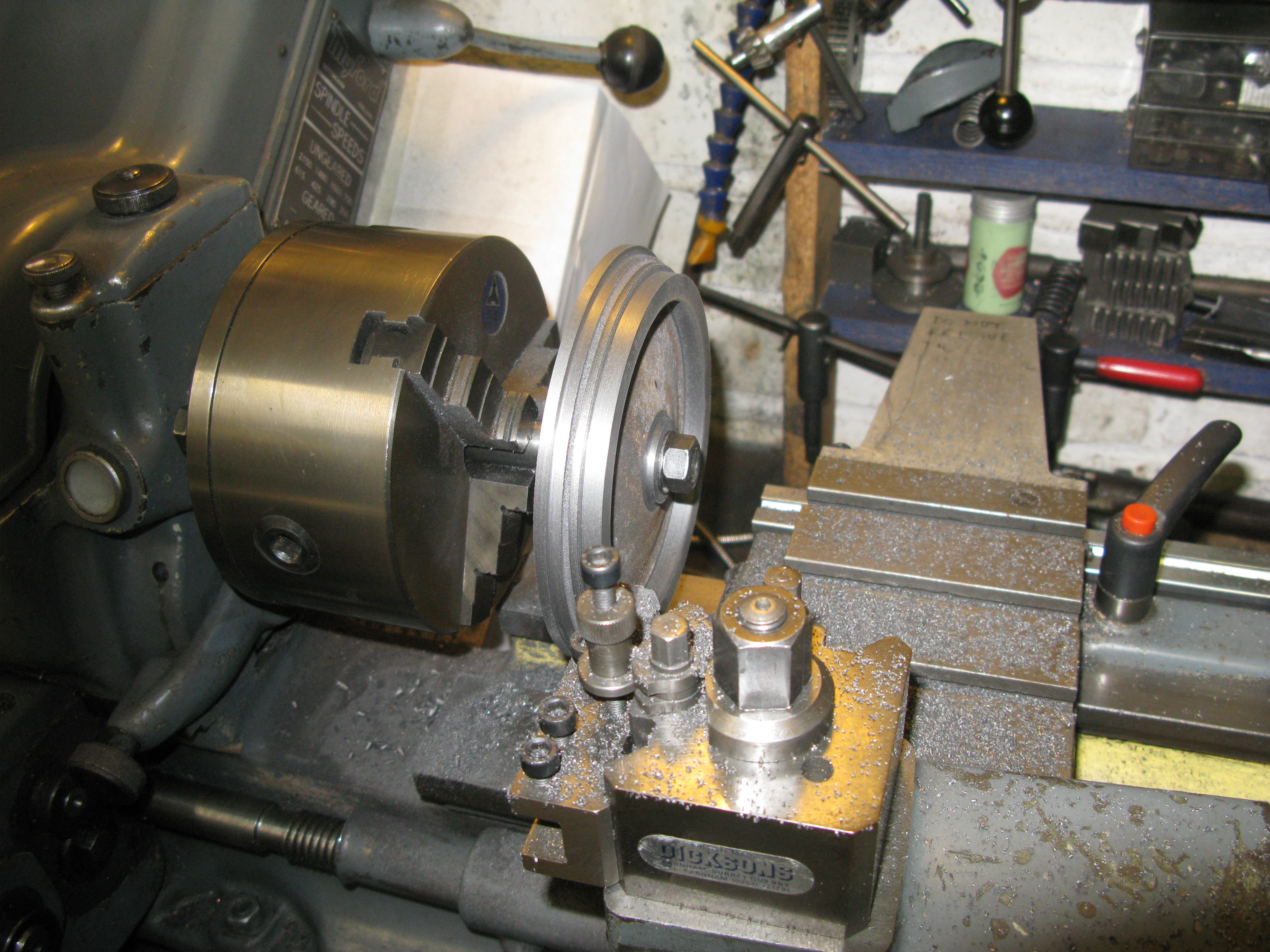
The curved fron face of the buffer is machined following a fixed guide mounted on the lathe bed with a follower mounted on the cross slide. The tool and follower are both on the same vertical center line.
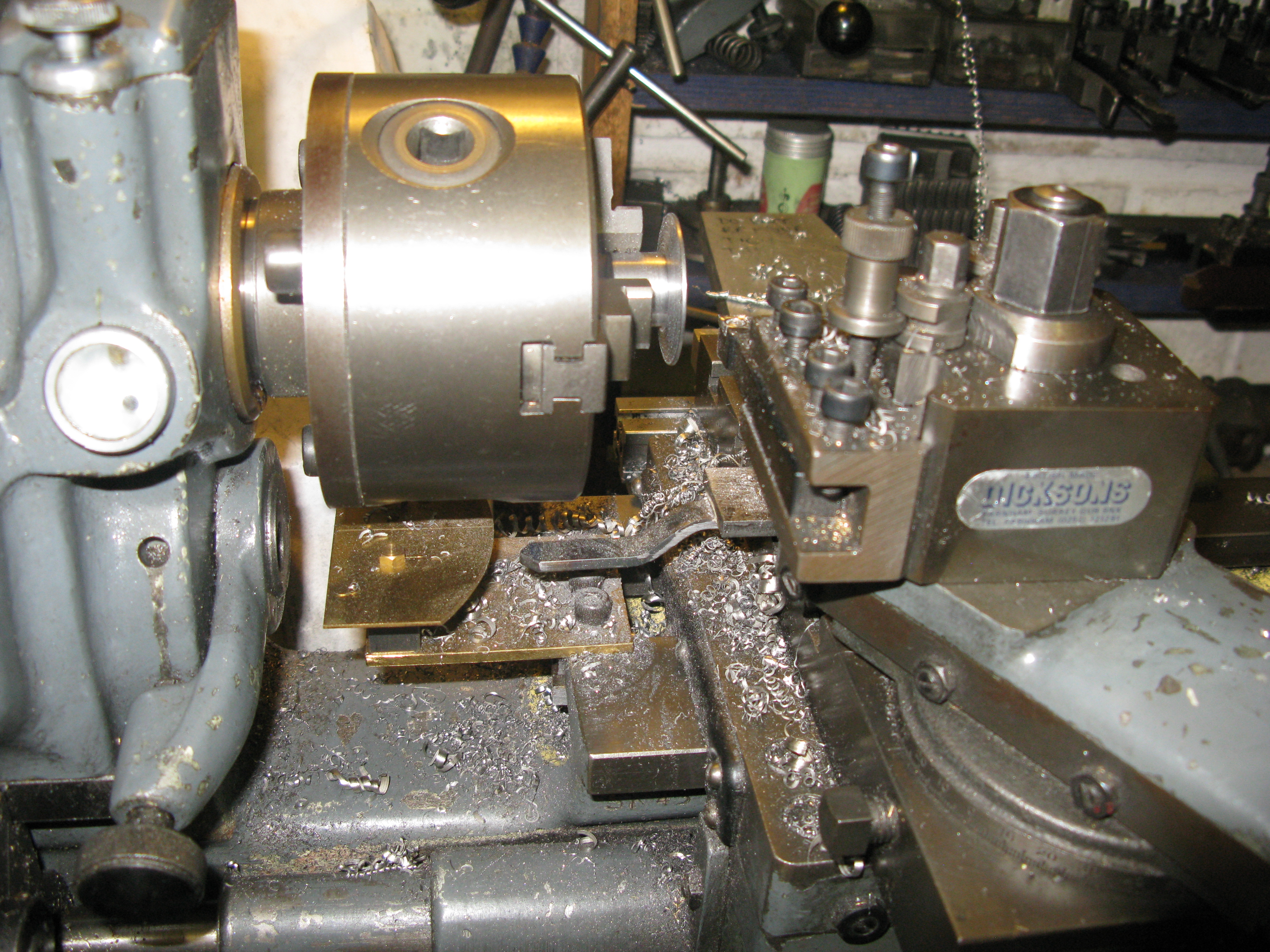
Initially the face is rough turned to approximately the right width and then the follower has to be adjusted so that when the tool is on the outer edge of the buffer at the correct width the follower is in contact with the face of the template. the top slide can then be turned in and the topslide will move back as the follower pushes against the template.
The buffer has a 1/4″ OD rod screwed into it 2″ long. The other end of the rod I reduced to 3/16″ and threaded 2 BA to accept a reduced 2 BA nut. This I found cleared the frame just nicely when all assembled but has enough back and fore movement in the relieved bracket to enable the buffer to spring in and out and not be able to come completely out.
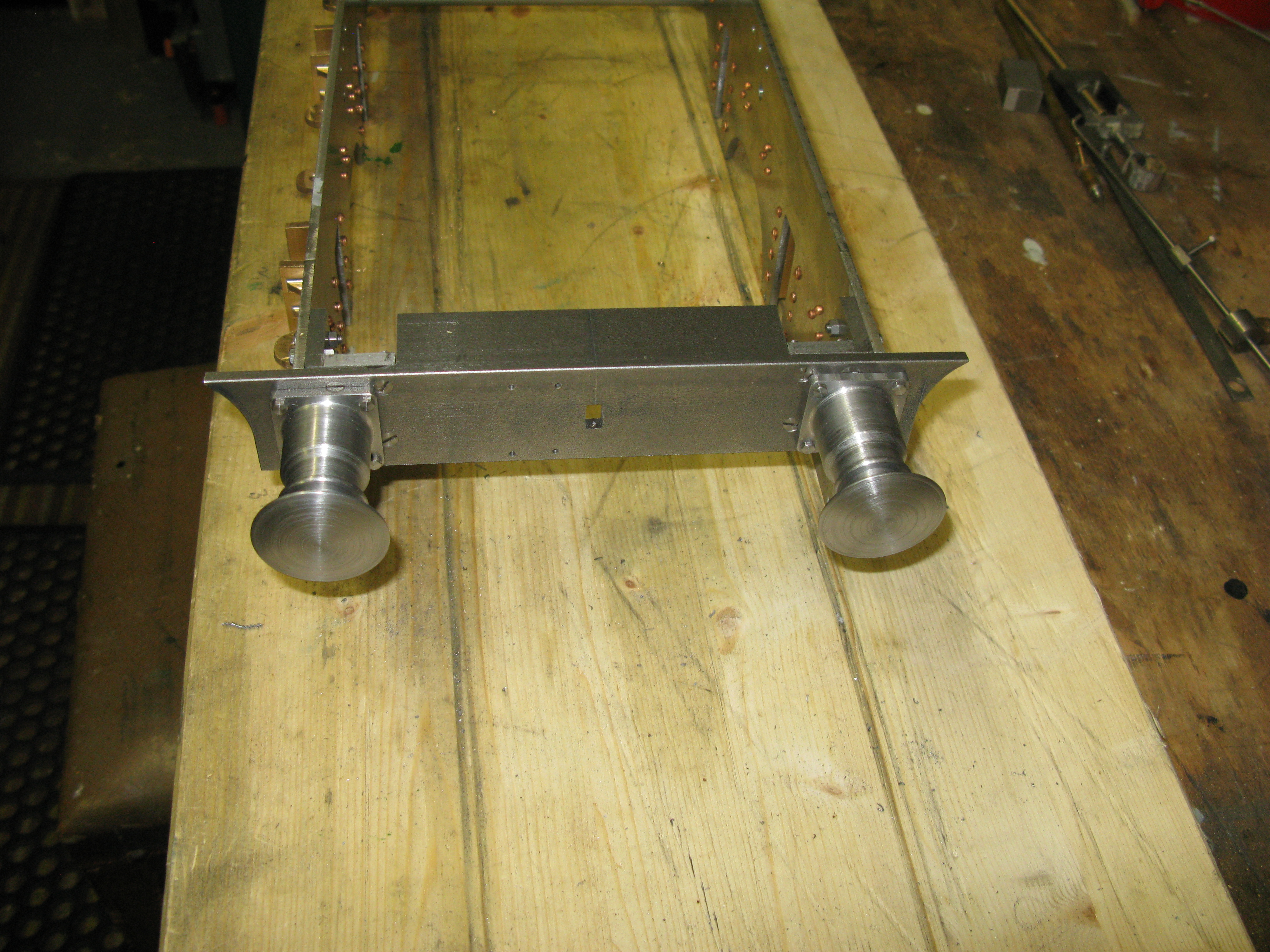
The assembled buffer beam
The buffer stock was jig drilled from the buffer beam for the four 8 BA fixings.
The front beam drag box is a silver soldered assembly of a top and bottom plate with 1/4 ” spacers at the sides.
It is bolted to the drag beam with reduced head 4 BA set screws.
The holes for the pin will be drilled when the tender floor is fitted.
There are four angle brackets fitted to the frames to support the tender floor. Thses are seen in the photo below.
All the holes to fix the tender floor to these brackets and the front and rear beams will be drilled with the floor clamped in position at some future time.
Axle bearing boxes
The axle bearing boxes are one piece castings and more casting problems were evident due to mould slip so the dummy cover fixings do not line up and the bosses are going to be difficult to get centred.
The first maching task is to turn the top boss that takes the spring buckle. This was done by using the four jaw chuck and getting the boss to run as true as possible. It is not dimensioned on the drawing but is readily established as being 7/16″ in diameter. The height and bore details are dimensioned.
The second maching task is to clean up the two sides. This was done by holding the work by the boss in the three jaw chuck in the dividing head. Knowing the centreline distance to the base and using a height gauge the side surface could be machined accurately to be exactly 1/2″ above the centre line.
Having done one side the dividing head is rotated 20 turns to do the other side.
The job is then returned to the lathe to clean up the bottom face so it measures the corerct distance from the top face.

The box is rechucked to do the axle bore but first the axle centre has to be found and centre popped. The box is set on its top on the mill table so the top boss falls into the mill table slot. Then using a height gauge the centre line can be marked on the axle boss according to the as drawn dimensions. The box is then turned on its side and again the centre line can can be scribed with the height gauge.
This shows up how far the casting is out as the centre of the boss is way off the cast centre.
With the box chucked in the four jaw using a wriggler in the centre pop the box can be centred so the centre pop runs true.
The face can now be turned so it is the correct dimension from the cast front of the box. Fortunately that leaves enough spare metal so the as cast boss can be turned off and the 1/16″ deep boss machined in place.
Once that is done the axle bore is drilled and reamed 7/16″ for 1 1/8″ deep.
The box is returned once more to the mill to machine the side slots.
The box is mounted on parallels in the vice and the a 7/16″ bar is put in the axle hole. This bar provides the datum for the slot dimension away from the centre line.
Having established the relevent surface datums to slot is milled.
With one side done the box is turned over and the other side machined establishing the datums is a similar manner.
All that remains is then to clean up the as cast cover.
With two axle boxes done an axle was made turned between centres as the axle will not go down the bore of the lathe headstock. The 5/8″ diam bar was first held in the chuck and a centre put in, turned around and the other end centred as well. This means the 5/8″ bar will not be truly symetrical about the centre line as the length extending from the chuck does not rotate true at the far end into which the centre drill is drilling. However when between centres the turned ends for the wheel bore and axle box bore will be true.
Having turned one end to the correct dimensions the axle is turned around and the other end rough turned having marked off the approximate point of the 4 11/16″ back to back measurement. Once a resonable shoulder is achieved the axle is removed from the centres and the back to back length measured to establish how much has to be turned away to acieve the correct back to back measurement. With this knowledge the axle is returned between centres and the second end finished to length and diameters.
With the axle fitted into both axle boxes will they freely slide into their hornblocks? ……. Yes…. a result!

Interestingly the as drawn distance between the axle boxes is 3/16″ longer than the length of the axle over the wheels giving a 3/16″ “slop” side to side. Yet the middle pair of axle boxes have their inside boss removed so increasing the side to side movemeny by 1/8″ overall. I checked this against my A4 tender and that too has the side to side allowance although I did not check if the middle pair was greater.
I have aslo now checked a couple of other loco’s built by club members and their “slop” is minimal so I guess its down to either the builders or as drawn choice. I will leave mine as they are.
All four axles and their boxes are now done.

There is more work to be done on the axle boxes namely the finishing off of the as cast cover. The problem here is that the two pips either side of the cover which form the area where the fixing bolts would be located do not line up. They are offset due to the pattern/mould slip mentioned earlier.

If you look at the photo above carefully you can see my scribed line of the centres of the fixing lugs, the right hand one being higher than the left. I am still in thinking mode about what to do.
So…. having thought ……. use the CNC to profile the cover, which is what I am now doing.
As the axle boxes are all slightly different in dimensions due to getting them machined out of the under sized castings each one has to be individually profiled, fortunately it does not take long to draw and the CNC operation is about 2 hrs with a very small cut of 10 thou. with a 1/8 end mill running at the max speed of the mill of 2000 rpm. Just another seven to do ……
The lugs have to be 1/8″ radius so both can be aligned. I will have to wait and see if that is OK for all axleboxes.
So, all axle boxes were OK with 1/8″ lugs and have now been finished.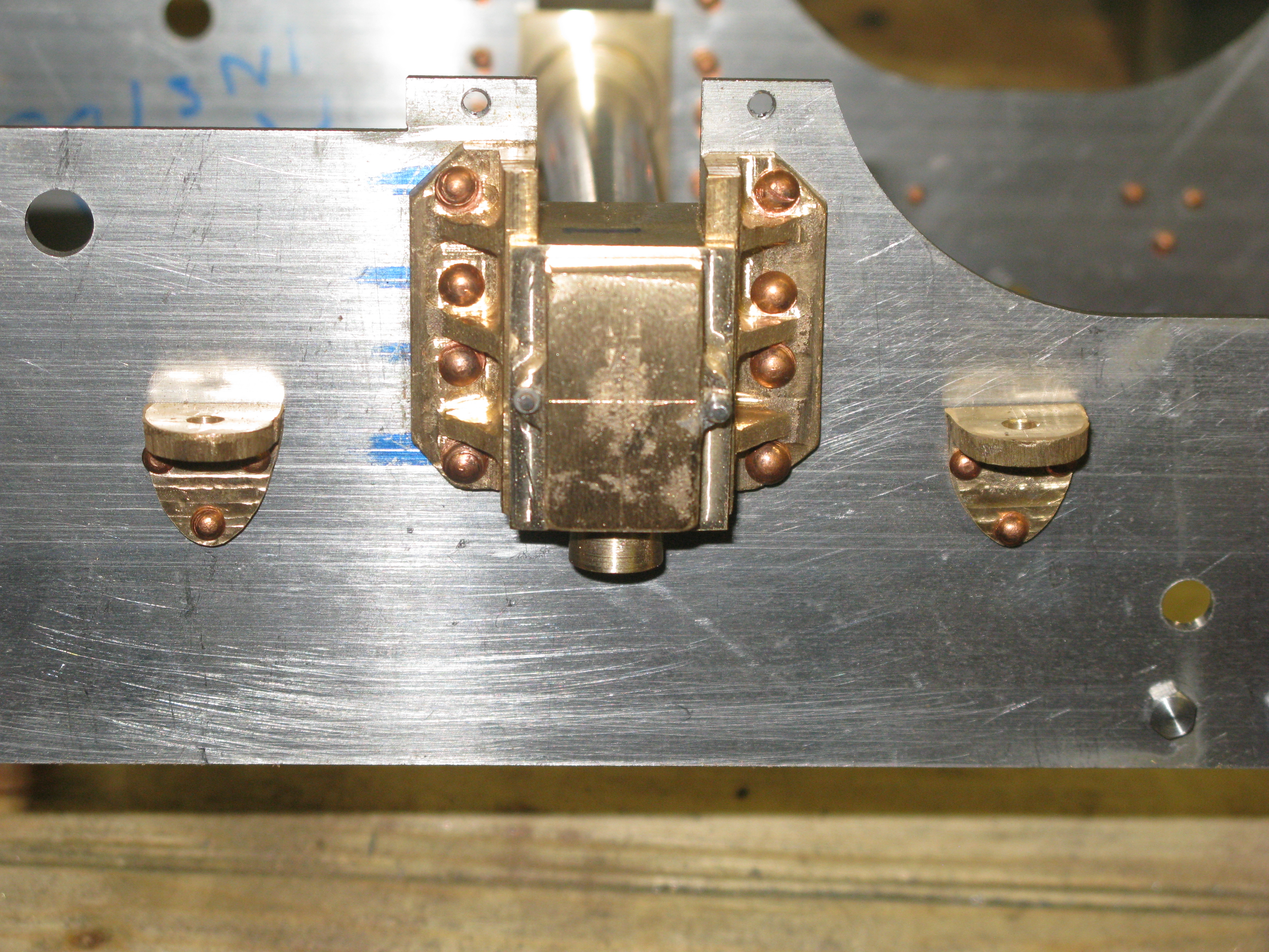
In the picture above can be seen the dummy cover fixing bolts which are 10 BA.
The next job is to make the axle box keeps. These are held in place by the tapped holes just above the axle box in the picture above. (The tender frame is upside down at the moment).
The keeps are simply 1/4″ x 1/8″ bar with two holes for the fixings. As I did not have any stock material of that size I used a slitting saw to cut the keeps from 7/16″ x 1/4″ flat bar that I had.
With eight keeps cut they were stacked together for drilling as can be seen in the photo below.
As the jewellers clamps are wider than the keeps there is a piece of scrap material (the bit sticking up) to pack out the keeps in the vice.
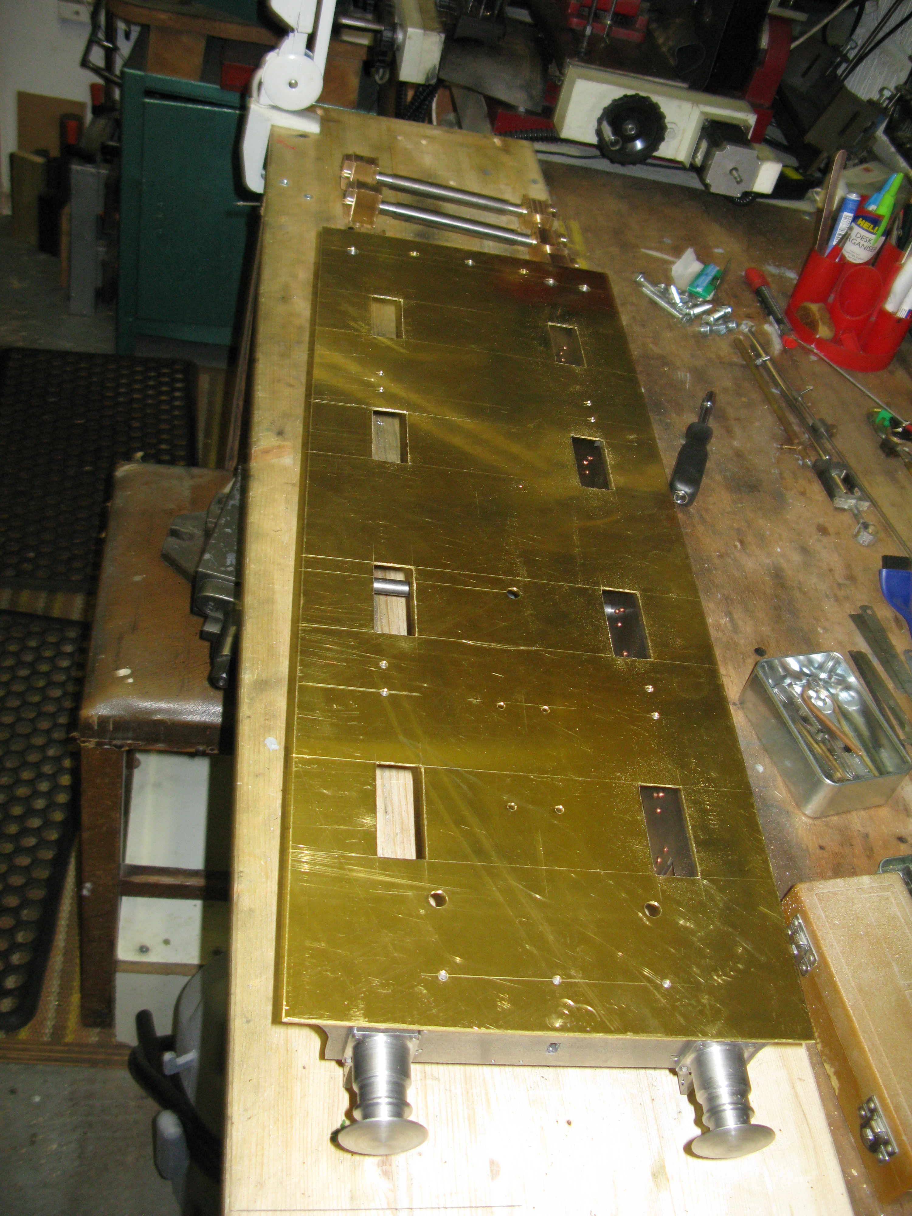
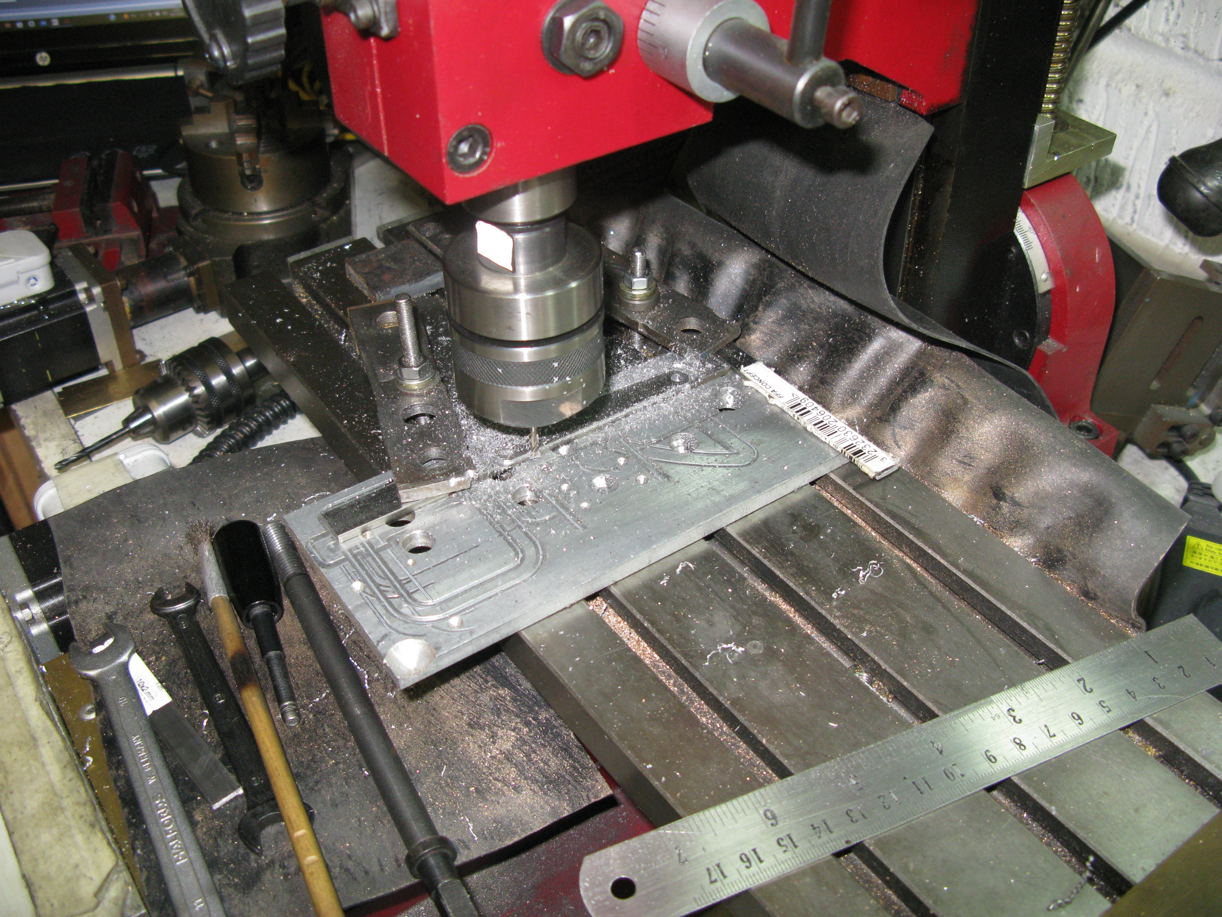
Next on the job list was to drill the sole plate. I bought the 16g brass cut to size so it was clamped to the frames in place so that all the holes that went through the frames would line up when drilled.
I did the drilling on the mill table and the clamping arrangement is as shown below.
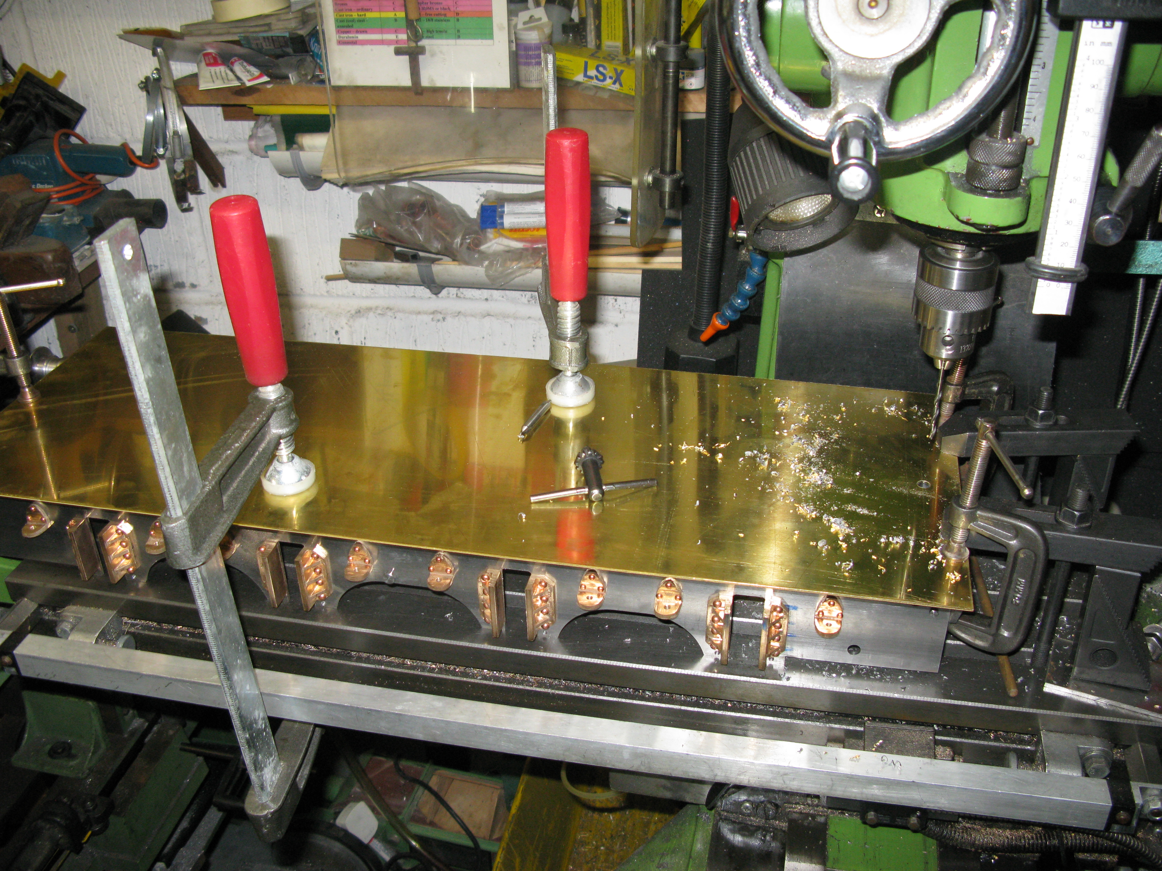
The frames were aligned parallel with the table and there are clamps at the right hand end both clamping the sole plate to the frames and then the frames to the mill table.. On the left another clamp to hold the sole plate to the frames and then the two large clamps holding the frames down on the table. This clamping arrangement had to changed four times as the frames were too large for the drilling to be done all in one setting and the frames moved to get the required holes to be drilled under the quill.
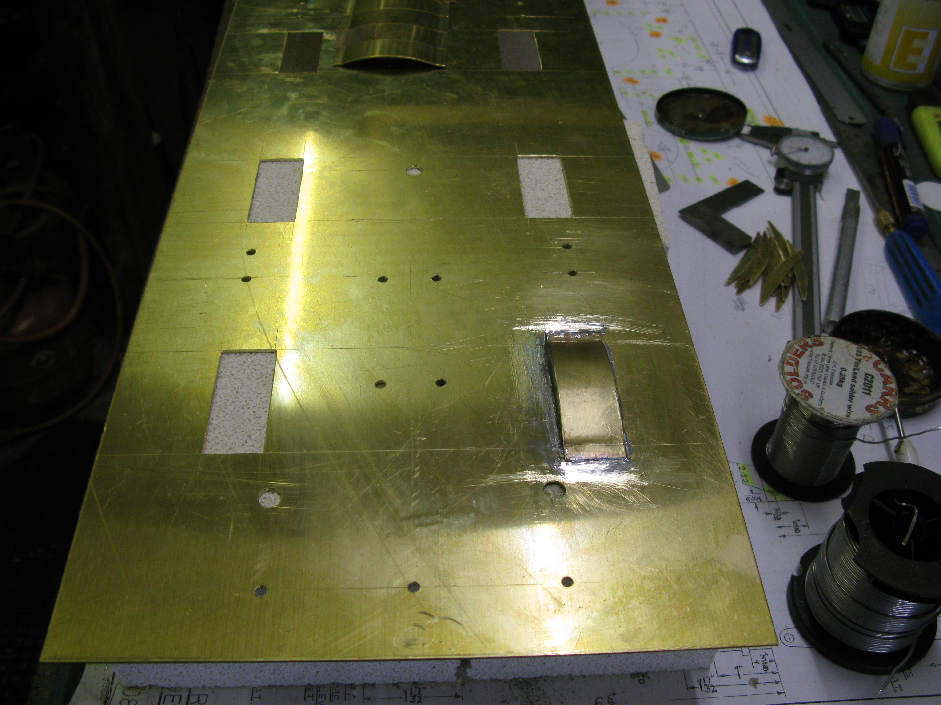
With all the holes drilled the sole plate was marked out for where the wheel splashers go.
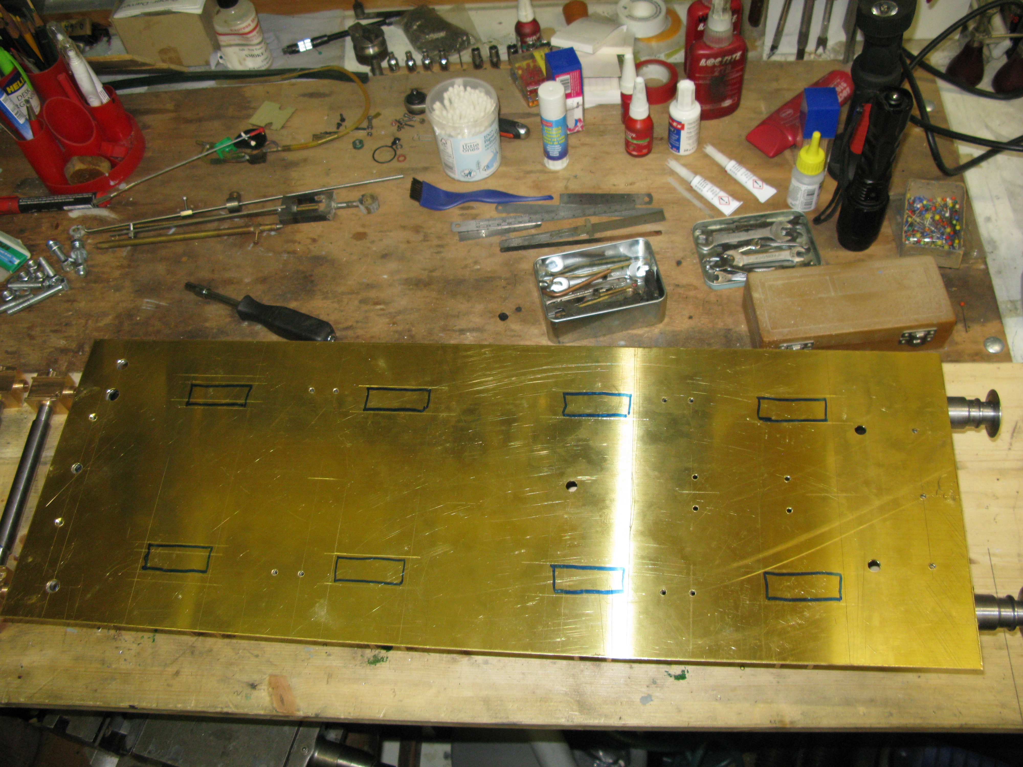
To cut out the slots for the splashers I chose to mill them out.
This was the easiest option and all eight were done with one movement of the work through 180 degrees.
The splashers are made of two sides and a curved cover. The sides were machined on my little CNC mill.

There are sixteen to be milled out with each operation taking 20 miutes to do two. They then had to be deburred.
The curved top was made by cutting a 7/8″ wide strip of 20g brass and forming the round form on the bending rollers to match the curvature of the sides. Each top was then cut from this curved strip, the ends were marked where the bend was to be put in and the bend formed over the sharp edge of the machine vice using a sharp chisel edge and hammer to get the bend tight.
With the components for the splasher done the time came to work out a method for soldering them in place.
I put the sole plate on three insulating bricks so one brick was directly under a slot. A side plate was positioned and using a 1/2″ bit soldering iron an attempt was made to solder it in position using 180 degree solder, having tinned both sole plate side plate and placed a supporting lump of metal to hold the side plate vertical. This did not work. The problem was that the heat of the iron on the sole plate caused it to bow which immediatly meant the side plate was not going to be joined to a flat sole plate. My next attempt was to use the gas torch but that resulted in the same bowing effect. Next I tried my resistance soldering unit but it was not man enough to heat up the sole plate to soldering temperature.
I finally had success when I twigged that using the soldering iron on the inside of the side plate rather than on the sole plate, the heat trnsfer through the side plate was sufficient to melt the tinned solder on the other side and enable a run of solder to be added. Having put both sides on using this method the top was soldered in place with a lower melting point solder (140 degrees) first by tacking the two ends and then by soldering from the inside of the splasher the joint around the curve. This was a bit fiddly with a large iron but it eventually was completed.
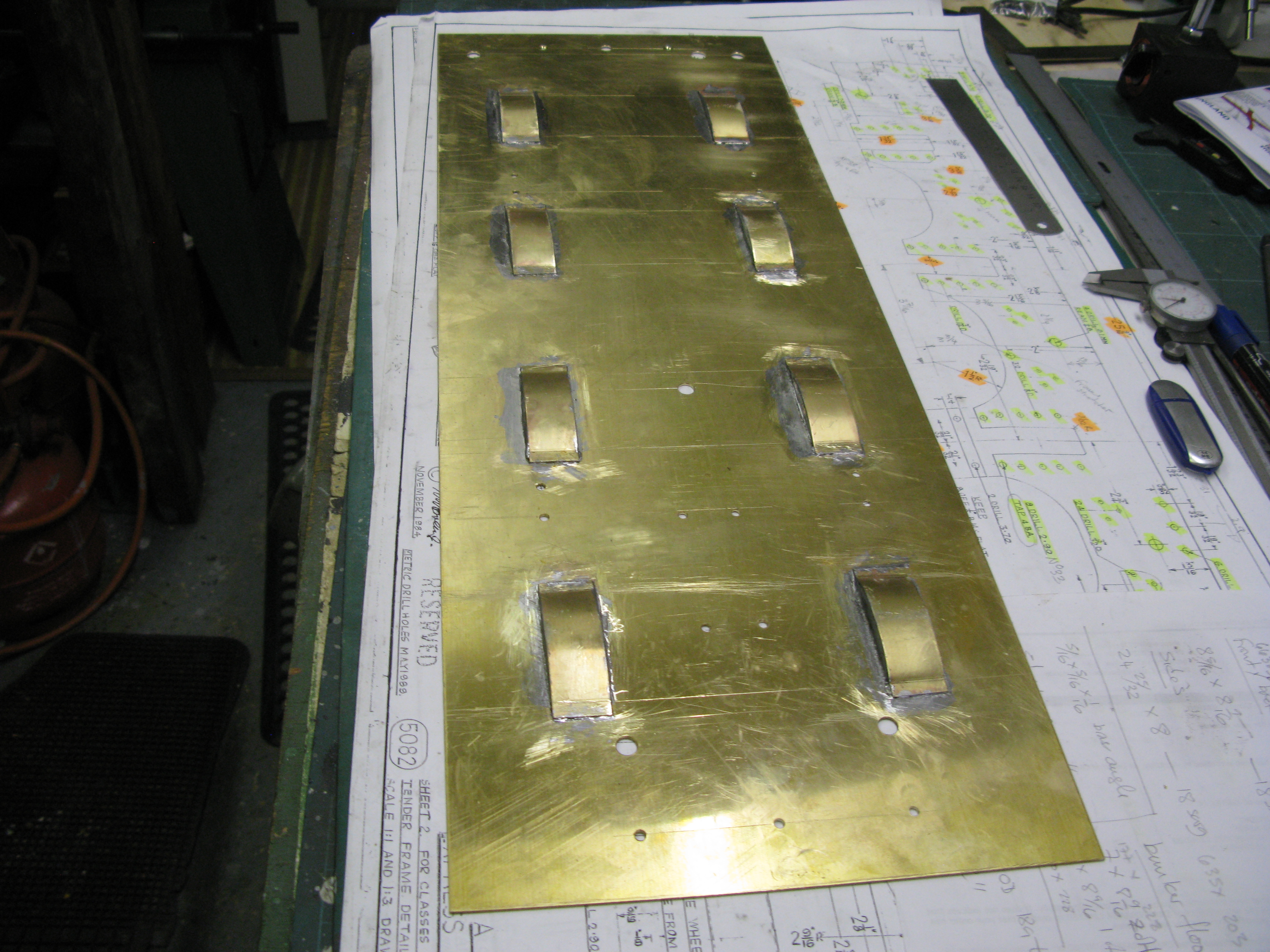
The first splasher soldered in position, at the top can just be seen the top covers.
With th soldering method proven all the splashers were fitted in position.
To be doubly sure there were no leaks around the joints I chose to coat the inside of the splashers with a fibreglass resin so that all the joints were covered. This I reaoned would minimise the risk of a leak occuring. It can only be realistically tested for leaks with the tender full of water so having the maximum head over the sole plate, and once the tender is built to do this test access to fix any leaks is going to be a little difficult even with tender off its chassis.
My next job is to give the chassis a coat of paint. I used three coats of etch primer from a spray can (as advised on the instructions) used in the motoring industry and then a coat of satin black as used on the loco. The horn blocks were all masked out before painting so the bearing surfaces would remain free of paint. The axle boxes have aslo been given the same treatment.
Wheels.
I have made a start on maching the wheels. The wheels are of the disc design so should be a lot easier to clean up than the spoked version. The first thing I came across looking at the drawing is that the wheel is drawn with a flat profile, not the usual coned profile. I could not find any reference on full size if this was correct but felt uneasy with a flat profile thinking the tender could more easily wander without the self centering ability of a coned wheel set. Took some advice on one of my forums (GL5) and the recomendation from there was to use a coned profile.
Having started on one casting I made a complete hash of it by confusing some width dimension as drawn between boss and tread, then tried to compensate (there was enough on the casting to do so) and then cocked up the tread angles, so all in all a complete disaster.
Holding the wheel casting in the four jaw chuck would have been OK as with some spacers between the casting and the chuck jaws there was enough casting to machine the front face and tread and bore for the axle in the one set up leaving only the back face to be turned to get the final width. However with the cock ups it meant I had used up too much material so when trying to correct my errors I had mounted the wheel on a mandrill which was OK until I screwed up on the tread angles.
So, back to square one.
I decided to check if the tread angles would actually fit to the as drawn overall diameters. Using my CAD software I drew out the wheel profile and found that the tread angle of 3 degrees to get the right flange depth made the overall diameter of the tyre outside measurement smaller than as drawn by 0.036″ on the diameter.
Having established this I proceeded to turn the first wheel to the modified dimensions
The wheel is held in the four jaw chuck with spacers behind so that the full flange width can be turned. The front face and boss are done first followed by the flange being rough turned and board to the axle diameter plus a thou and half to allow for the Loctite fixing.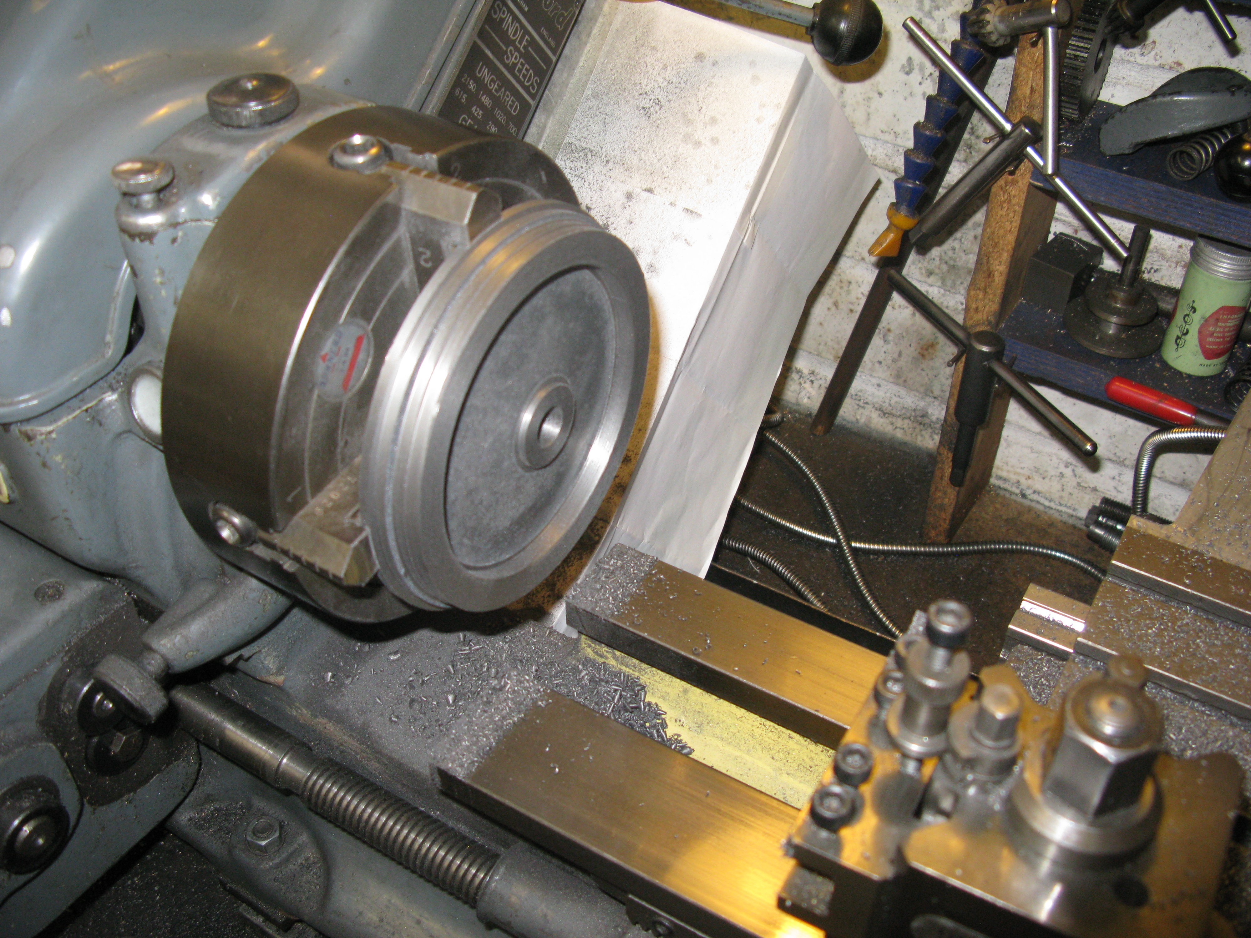
The wheel was then mounted on a mandrel in the three jaw chuck. This mandrel was turned to be concentric and remains in the three jaw chuck undisturbed.
The wheel flange and rear of the wheel can now be turned to finished size, angles and width. The final machining operation was to put the wheel back in the four jaw chuck and machine the rear boss to size.
All eight wheels were succesfully done and put onto their axles with Loctite securing compound. To do this the axle was set up on the lathe between centres with a wheel in place. The wheel was moved off its axle at the tailstock end to apply the Loctite and then put back on the axle and rotated to get a good smear of the retaining compound. The axle was then manually spun to ensure it had no wobble and left for the Loctite to go off. The axle was then turned around and its other wheel mounted the same way.
The wheel set was put onto the tender frame and the frame (unsprung at this stage) given a test roll on our club track to ensure it rolled OK and all wheels were rotating freely and uniformly.
Springing
The springs are drawn as being made from spring steel for the top and bottom leaf withe Tufnol leaves in between. A not says that for more rigid sprining the top two leaves can be spring steel.
The drawing also showed the spring as being flat, i.e. no curvature on the leaf spring at all. This concerned me as it effectively gave no spring function at all, and if any it would be a revearse bow. I decided to make the top two spring steel leaves with a bow. The Tufnol leaves cannot be set in a bow anyway so remain flat. I think with the fully laden tender they will end up flat which looking at full size photos most tenders were.
The spring steel was obtained in an aneald state so the bow could be easily achieved in the bending rollers. The holes at the ends weres drawn as a simple hole but with the bow, I put in elongated holes to allow for the bow movement.
Machining the end hole in a jig to ensure centrality etc in all leaves
The next issue was how to hold the leaves in place. They are of course quite tight in the buckle when assembled but could still with time, move from side to side. So I decided to fit a central pin to prevent such movement. This meant making a modification to the buckle.
To make the buckle and get a nice rectangular hole a piece of steel was first milled with a long slot the width of the leaves and to a depth of the spring assembly. Each buckle was then sawn off and a plate silver soldered on to form the buckle hole.
Milling the slot. The oversized width on the near side was machined to the correct width.
The sawn off buckles were then milled down to the correct width.
The buckle was then mounted in the four jaw chuck and its spring retaining boss machined.
As I was having a central pin to hold the leaves in place the pin (which also had to be removeable) was made with a 5BA thread at its ends which screws into the spring retaining boss of the buckle which is of course tapped. The pin is 3/32″ diameter and the buckle is drilled right through at 5/64″ so as to give the pin easy entry through all the leaves on assembly.
All the springs were assembled and trial fitted on their axle boxes. And the photo below shows the big blunder …….. they are all upside down!

The springs all had to be taken apart a assembled the right way up, and painted.
The spring hangers are turned from 5/16″ mild steel. A fairly straight forward job, but it does require them to be turned using a rotating centre at the tailstock as at 5/32″ dia. they would other wise tend to bend away from the tool.
The hangers were then all trial fitted to the springs on the tender before making up the dummy damper blocks (spencer blocks).
The spencer blocks arrive as a stick of four cast in gunmetal. They were not particularly well cast in as much that it was not possible to get the as drawn finished size due to the draw on the casting. I decided to reduce the size of the plan view all round and then machine them on the cnc mill so they all finished up the same size.
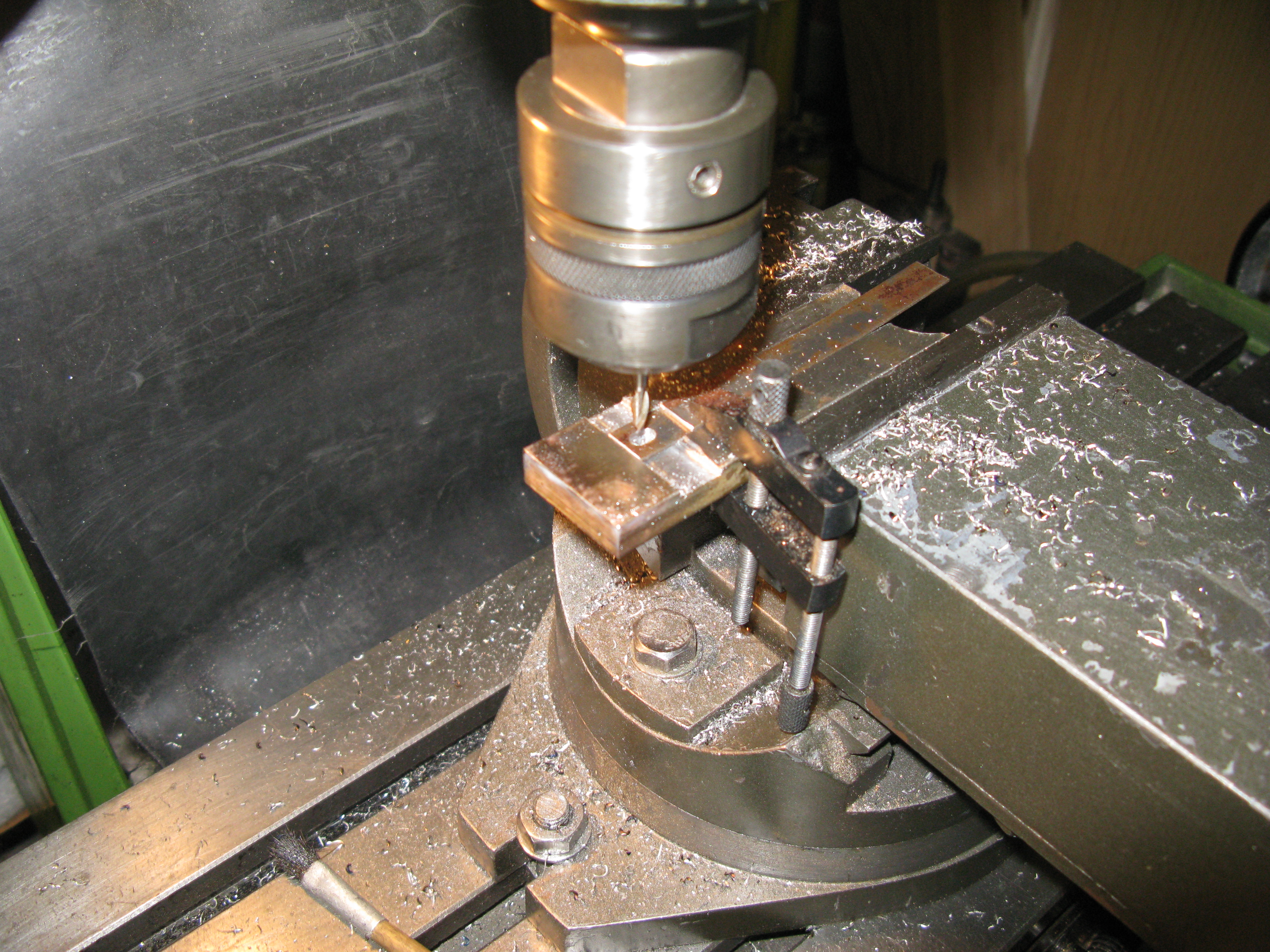
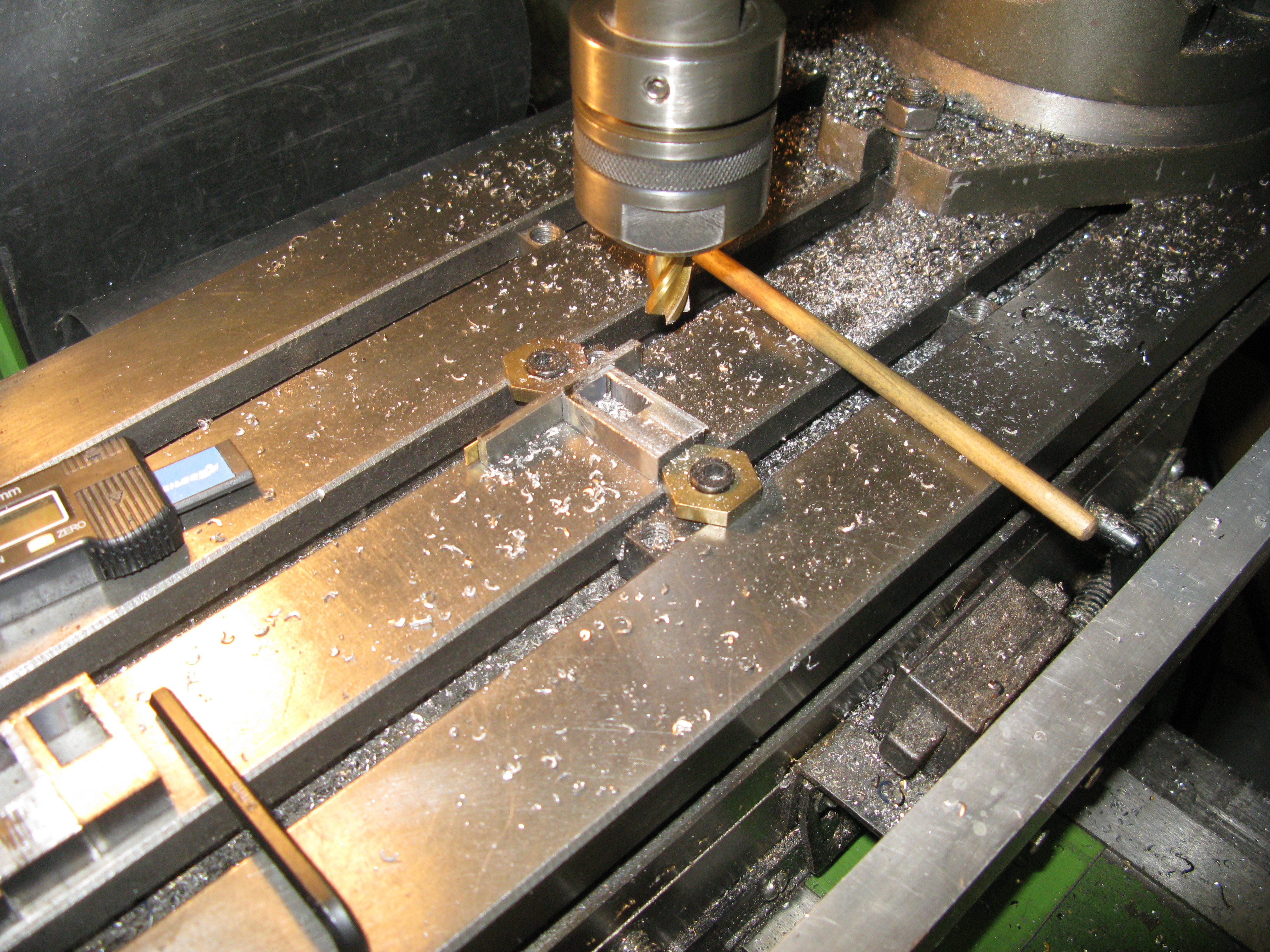
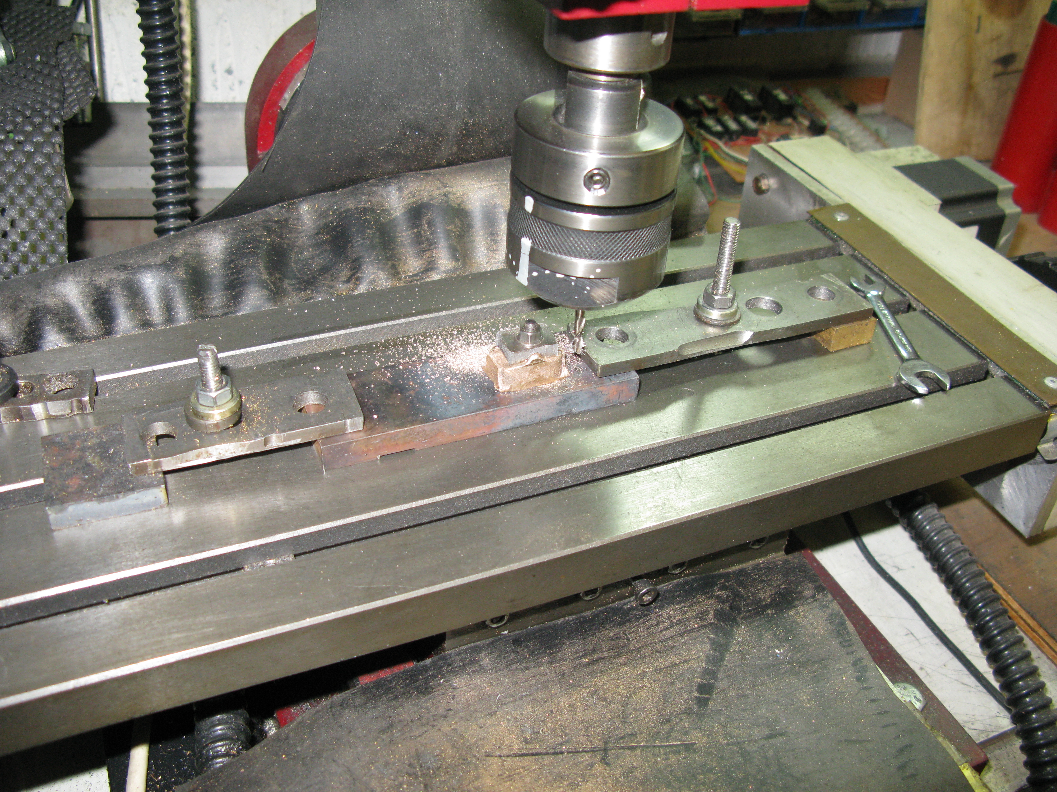
The first job however was to drill the centre hole so that it was in the centre of the raised top ridge. This was not as easy as it looked. I made a small jig with a half round trough to sit over the ridge with a central hole. With a block in the vice the drill was centred and the hole drilled. As there was no mecahical means to hold the jig down it relied on my thumb pressure to keep it in place. This resulted in the jig moving slightly on occasions with the resultant hole being marginally off the centre of the ridge.
To cnc machine the block I made a jig with a 3 BA threaded screw silver soldered in place onto which the block and the drilling jig could be fixed. With this jig and the single nut locking the block down and using light (0.015 thou) cuts the block was machined. It took about 40 minutes to do one.
The finished blocks were then etch primed and painted to give the finished assembled arrangements seen below.
The springs will all be balanced when the full tender is completed and the locknuts on the spring hangers secured in place with loctite.
Brake gear
The brake gear consist of a shaft between the frames with levers conected to the brake handle and the brake bars that connect all four wheel brake blocks on their hangers. The brake bars are doubled, that is two, one each side that connect on both sides of the brake hangers. These brake bars provide for no adjustment of individual brake shoes at each wheel position being solid along their entire length. The only adjustment is from the brake handle operation shaft to the brake bars which connect with screwed rods with clevises at each end.
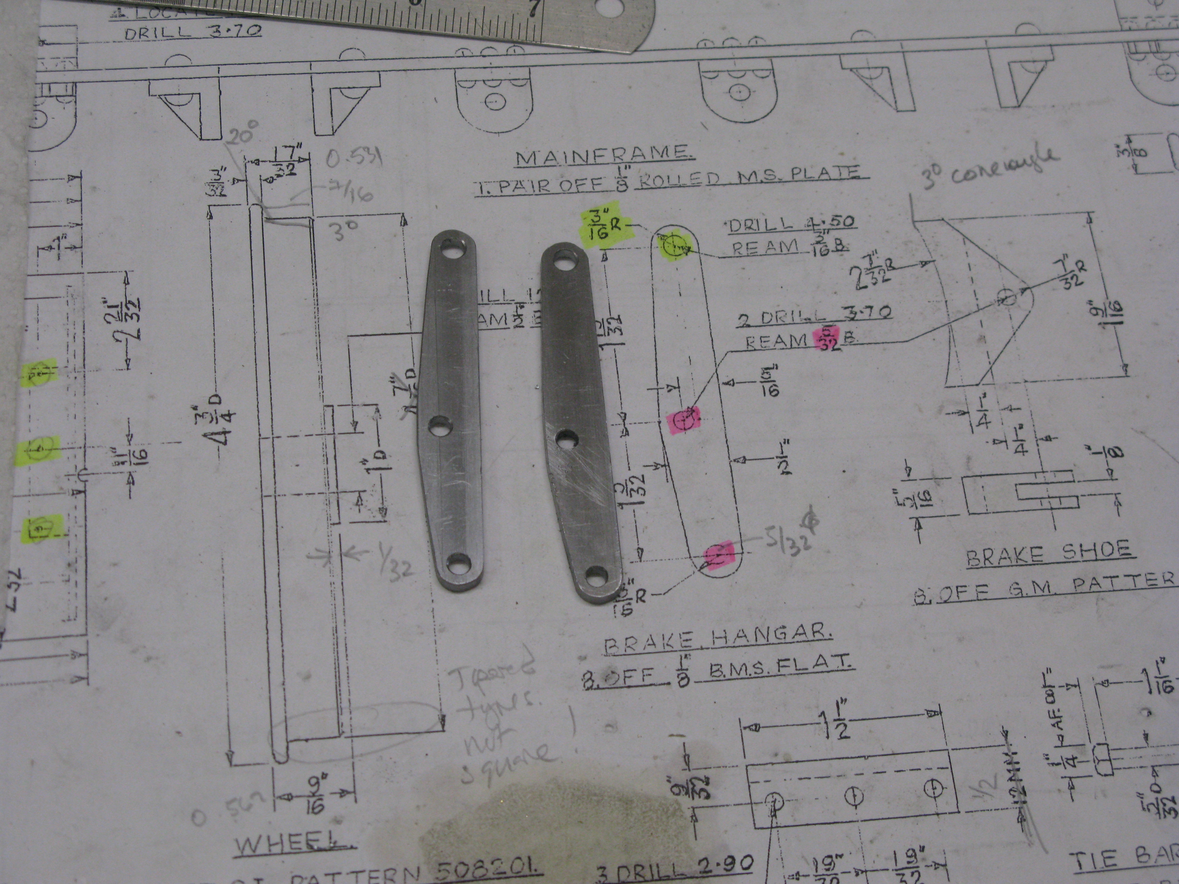
The brake hangers are made from 1/2″ x 1/8″ MS flat bar and have a tapered profile top and bottom on one side either side of the brake shoe connection. I chose to CNC machine this simple shape which ensures they are all the same.
The finished shape looks like this:
Out of interest the following image is of the CNC screen. The right hand pane shows the contour being machined. The left hand pane shows the G code and its progress.
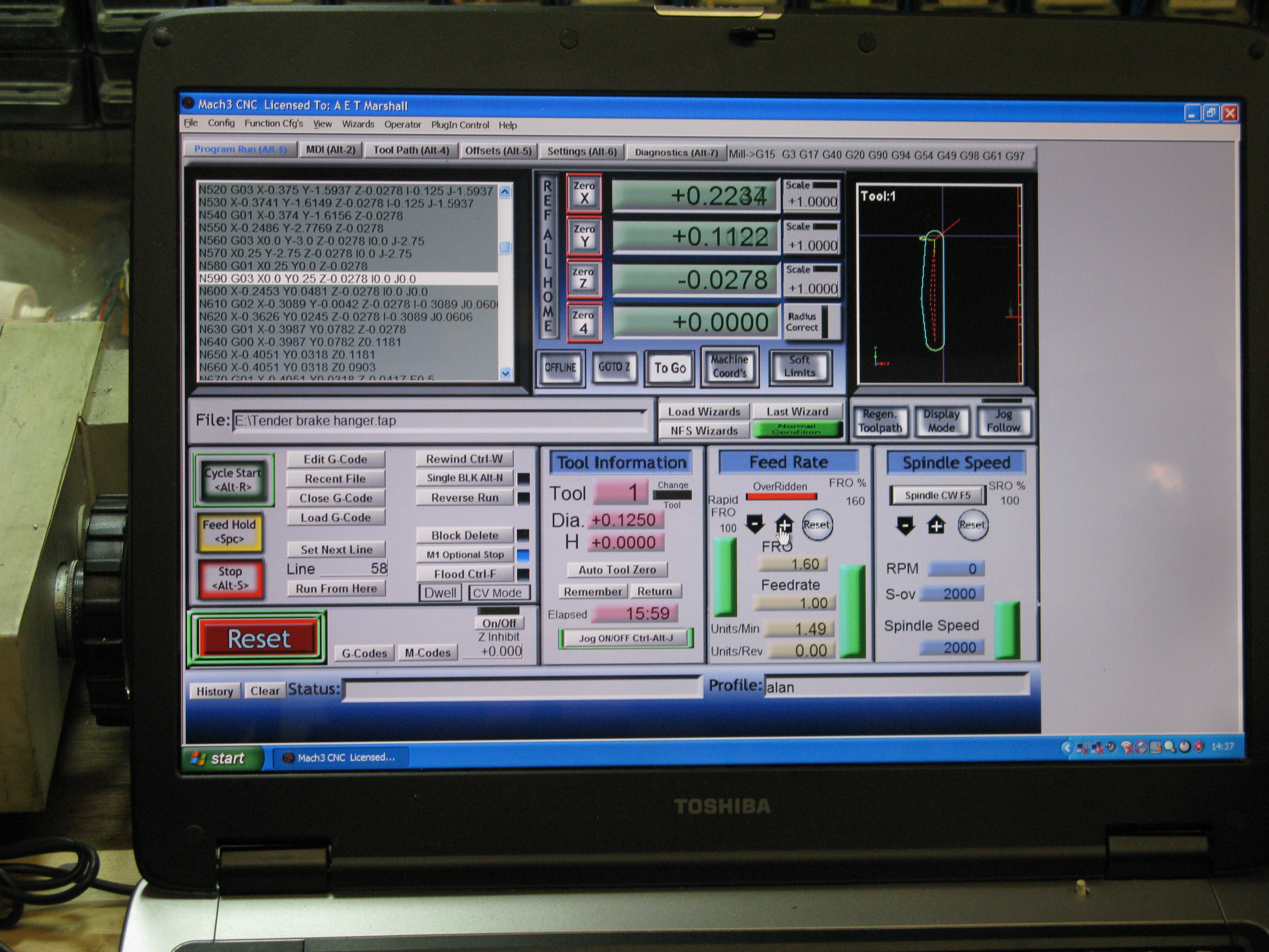
The middle pane shows the current position of the tool. Everything below these panes provid either information as headed or controls to stop/start and other managing instructions.
The brake hangers are mounted on extended screwed pins through the frames.
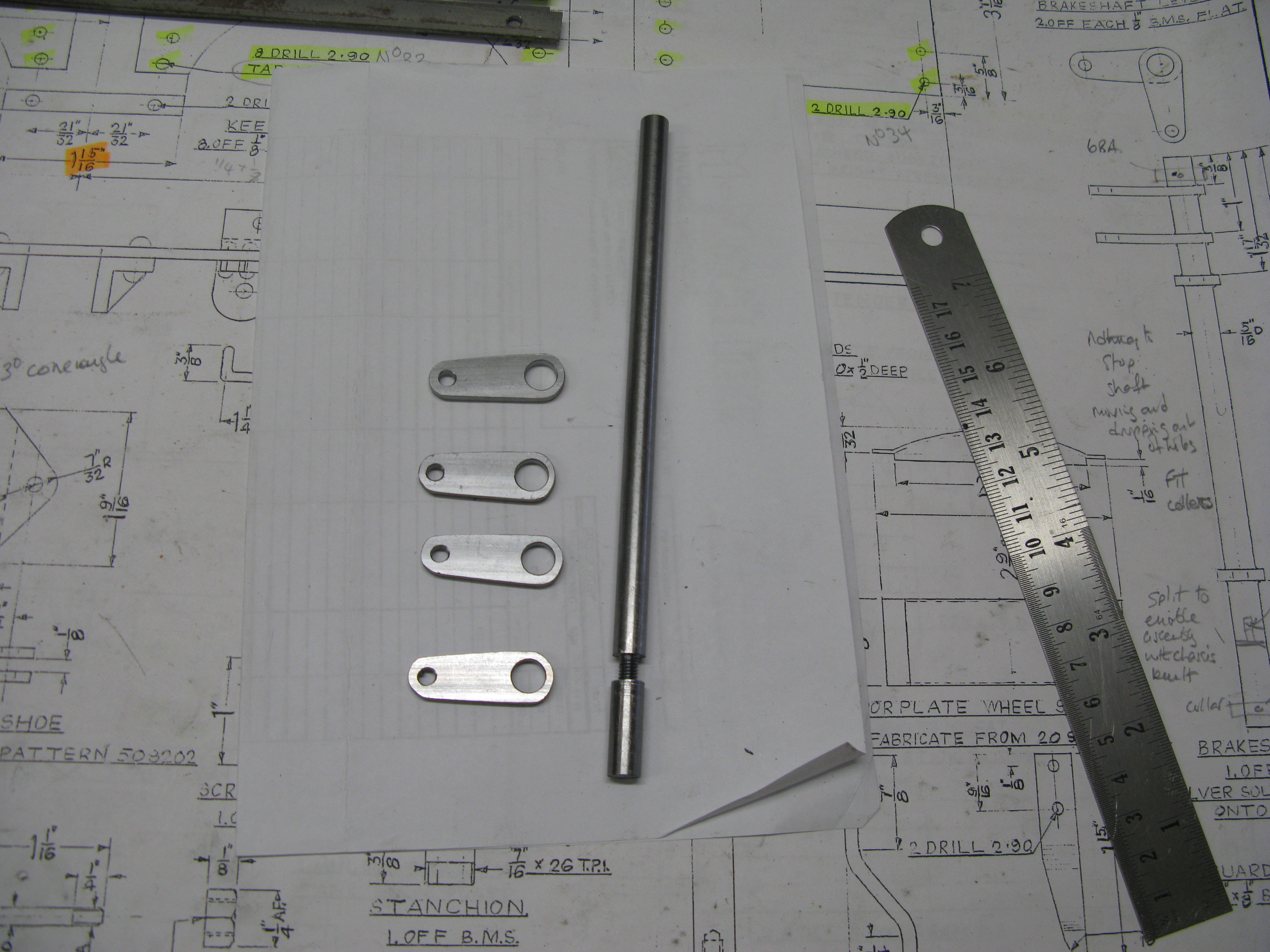
The brake shaft is from 5/16″ diameter MS and the levers are silver soldered in position. The shaft is mounted between the frames into a 5/16″ diameter hole in each side. The problem is of course that with the frames already assembled it is impossible to install the shaft. My solution to this was to split the shaft into two components that screw together by a 2 BA thread. This enables the shaft to be mounted in one hole and then the other pushed through the seond hole and screwed into position and eventualy secured with Loctite.
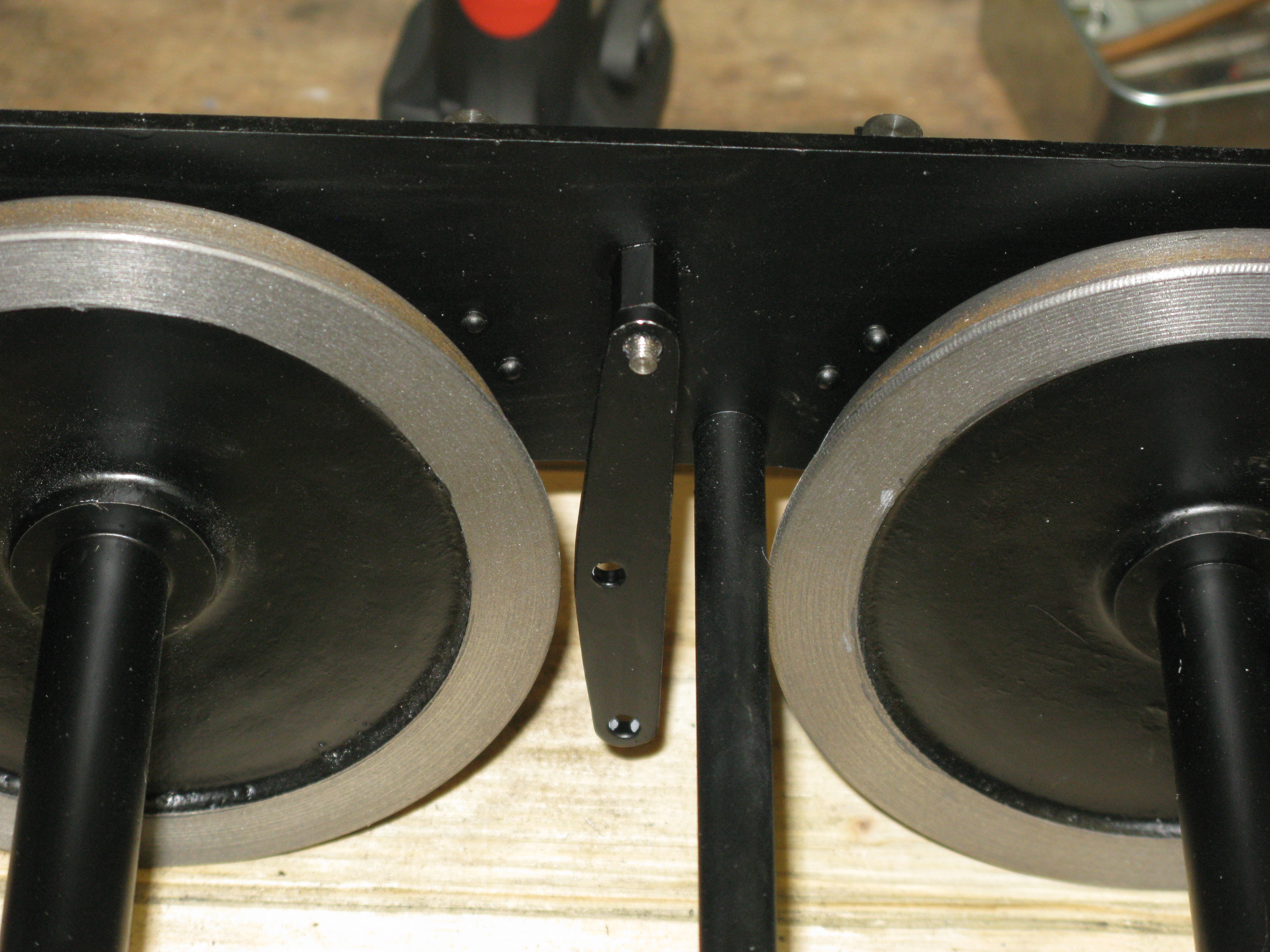
With the shaft checked in its installed position a further problem arose. The wheel flange fouled the lever and that prevented the side movement of the axle.

To overcome this I just filed the lever profile downto remove the fouling point. This still left adequate material of the lever around the shaft diameter.
A further issue arose as the drawing shows no retaining collars to prevent the shaft from moving sideways and dropping out, so I have mounted two brass collars held in place with 6 BA grub screws to prevent the sideways movement of the shaft. I doubt that with all the brake gear assembled the brake rods would have provided sufficient side stiffness to prevent the shaft dropping out. (having written that I subsequently found on another drawing two collars!).
The fitted shaft
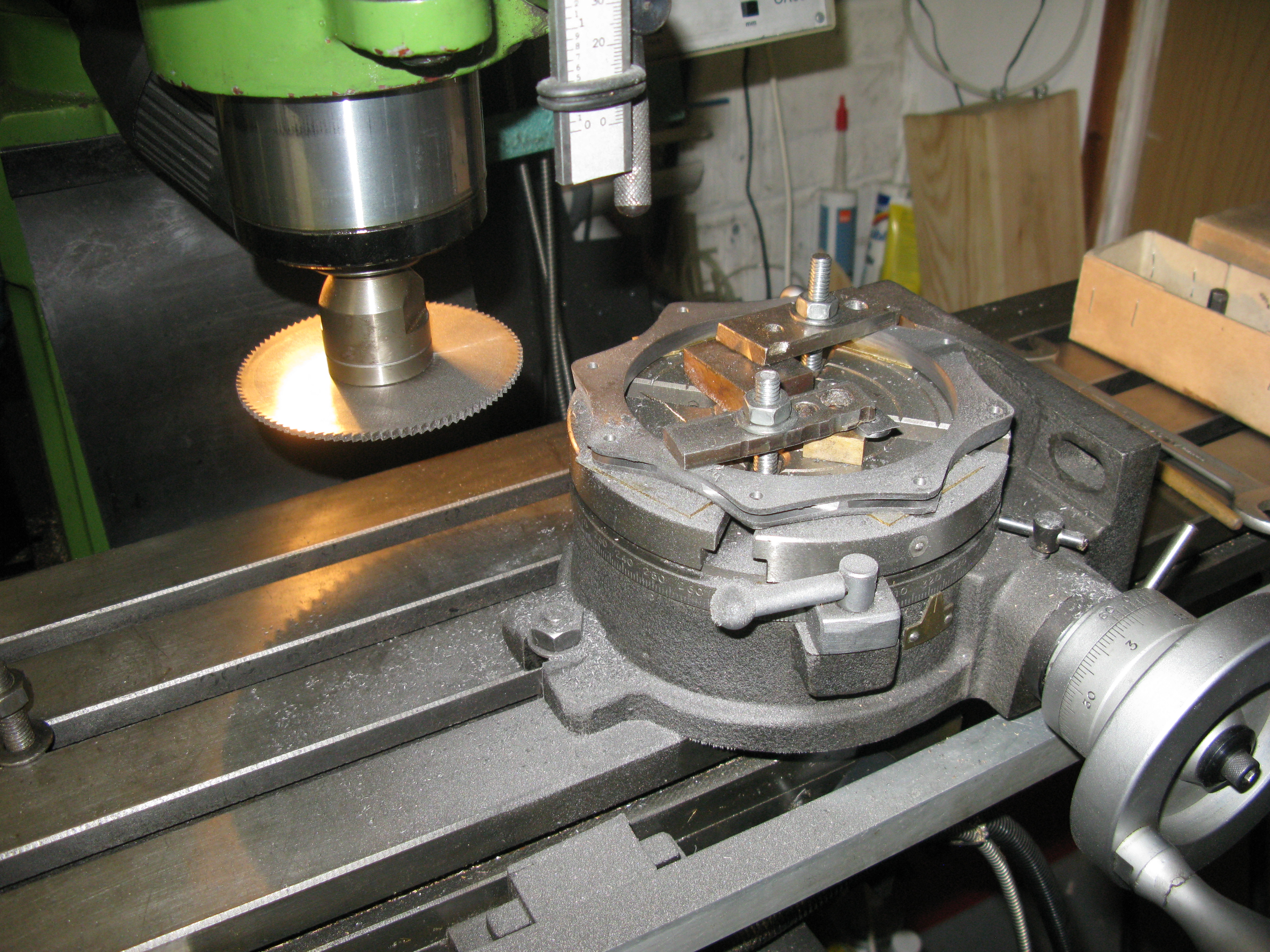
The brake shoes come as a casting of eight in a circular arrangement. The shoes have a raised profile on one side which is thicker at on end of the shoe than the other. I cannot find a reference on full size to see if these are right, they certainly do not match the drawing and the overall profile.

I decided to machine the inner diameter first and mounted the casting in a self centering four jaw chuck and it ran reasonably true. I faced off to get a reference face and turned the casting around and faced off the other side. I then tackled the bore. However when turning to the final bore it was not cleaning up the casting at one point on the edge.
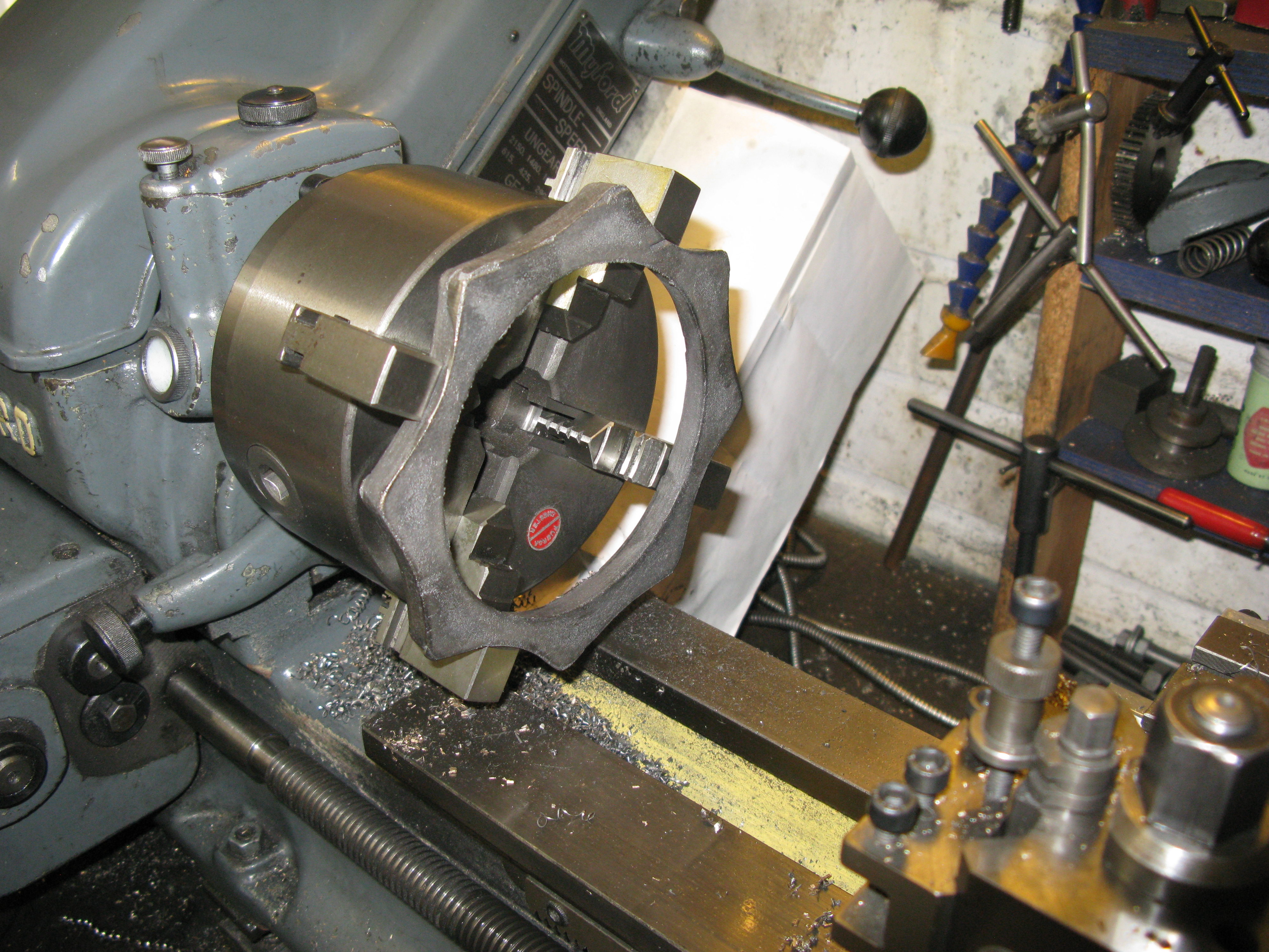
As it happened the edge that was not cleaning up was the raised profile side. I decided that the raised profile was not correct for the tender and faced the profile off which then gave me a clean edge to the bore. With the casting in a three jaw chuck and held by its bore I finished the casting width to size of 5/16″.
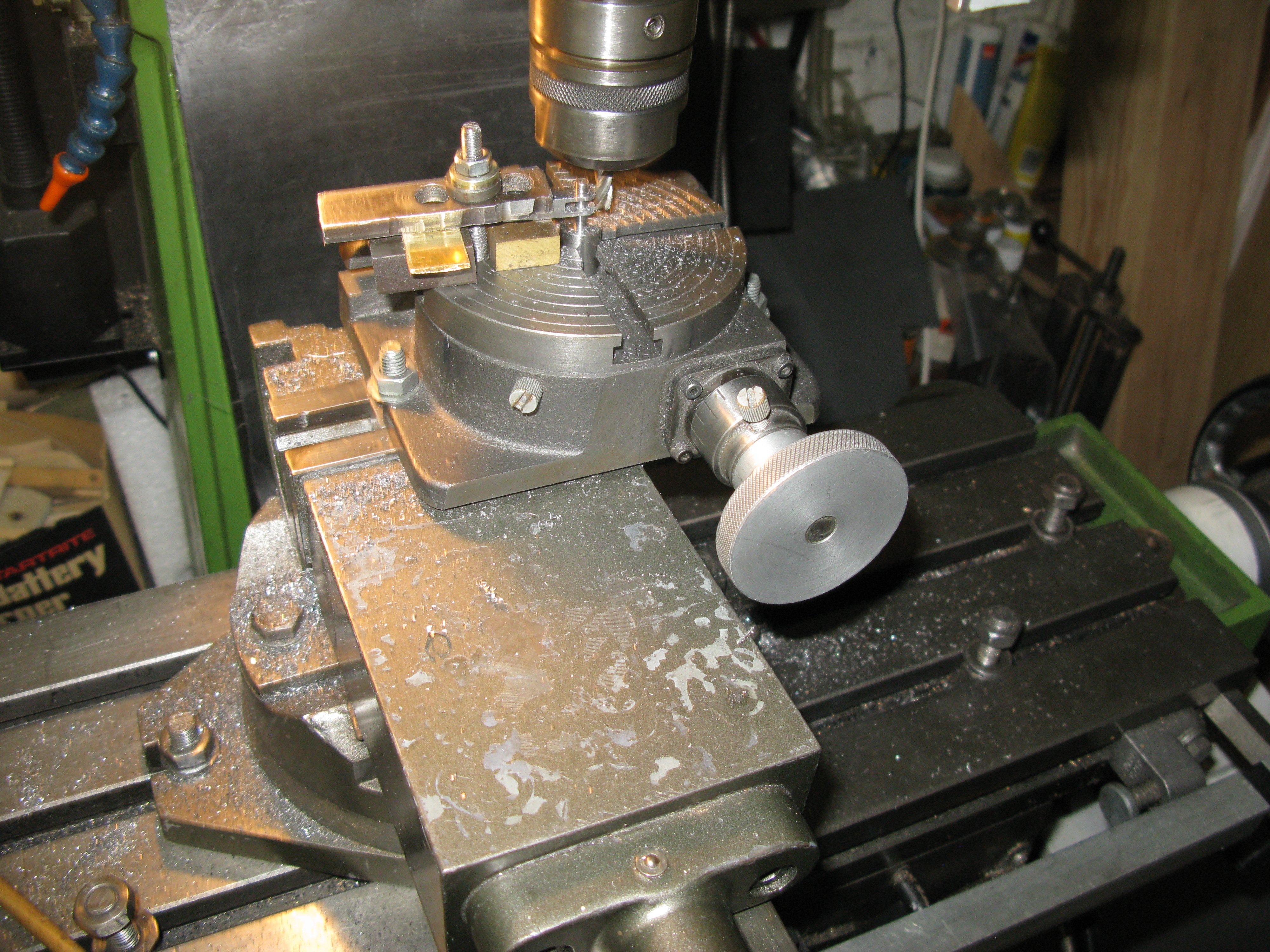
The next task was to machine the slot for the brake hanger and the hole for the pin. To do this I mounted the casting on a rotary table on the mill and centred it by reference to the internal bore. I then set about drilling the holes for the pins. This showed up the fact that the shoes were not evenly spaced around the casting but haphazardly spaced so I could not index the table around to drill the holes as I expected to be able to do. Accordingly I had to use my best judgement to get the holes positioned as best possible to fit the apex of the shoe casting.
With the holes drilled a 1/8″ saw was used to cut the slot.

All pin holes drilled
Machining the 1/8″ slot.
With the slots complete the shoes were manually cut from the ring and then set up on the CNC mill to profile the shape (not the bore).
The final resulting shoes are shown below some done, others waiting to be done.

The shoes when fitted look like this:

This photo is taken from the inside so the shoe is behind the flange. The movement of the shoe has scraped the paintwork away on the hanger. ( the right hand wheel is not as close to the stretcher rod as it looks).
The brakes are operated by a pair of bars that fit one ech side of the hanger and wheel set with spacers. These bars, which connect all brake hangers together have no means for individual adjustment of the brakes. They all operate at the fixed distance of the connections between the hangers on the bar.
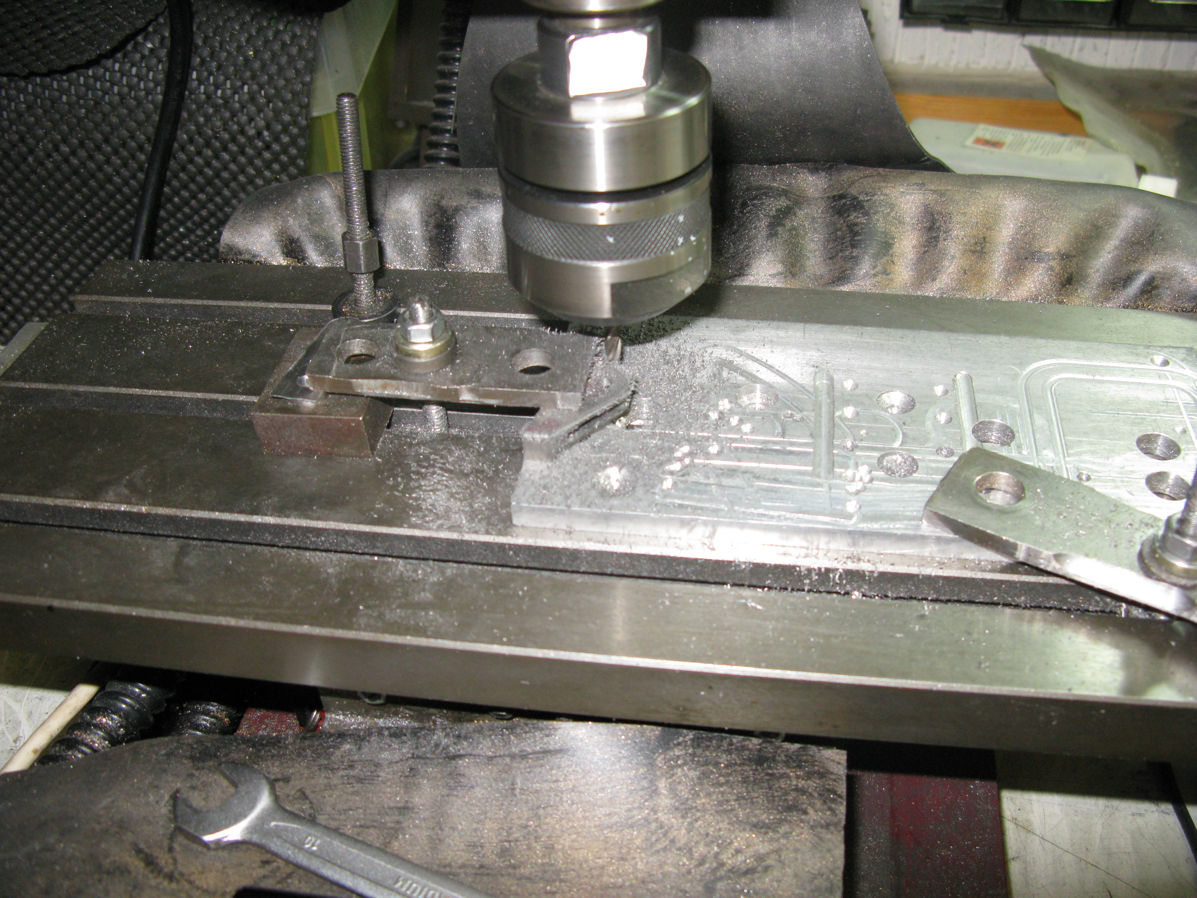
The bars are profiled, i.e. they are thinner either side of the point of fixing of hanger to bar with the fixing point being circular at a diameter the same as the spacers. These bars could be hand filed but what a task! So I chose to CNC them. This is not as straight forward as it sounds. They are only 3/16″ wide with 5/16″ dia. circular profile at the fixing points. This means they are quite flimsy being ony 1/16″ thick. An added complication is they are almost double the length of the maximum length I can fit on my small CNC mill.
This means the profile would have to be machined in two set ups. One to do one end the second to do the other end. The clamping arrangement had to be quite solid but easily adjusted, (you will see why in a moment) to ensure the bar did not move whilst being machined. So I ended up with something like this:

The two end clamps are fixed for the whole machining process except for the last cut. The two middle clamps get moved around. The cut on the far side can be done with the middle clamps undisturbed as they only go over the bar to the centre line. However on the way back these clamps have to be moved so the cutter can pass. The process involves moving the clamps whist the mchine is running. As the cutter approaches a clamp the clamp behind the clamp the cutter is approaching is moved up to the ‘front’ clamp. The ‘front’ clamp is them moved to behind the cutter once it has passed. The ‘rear’ clamp an then be moved fiurther down the work. As the cutter approaches the ‘rear’ clamp the front clamp is moved up behind the cutter and the rear clamp moved further down the work. This process is repeated for every complete pass of the cutter. On the final cut the middle clamps are near the end of the bar with one quite near the end to ensure when the material is totaly machine away and the end clamp doing nothing to hold the bar in place there is sufficient clamping pressure to prevent movement. Once the cutter has passed right through the bar and moved up towards the nearest clamp the end clamp is moved to clamp on the completed bar end. The middle cutters then continue their waltz up the bar till the final cut finishes.
This process is time consuming as the machining has to be watched because manual involvement is required, and it can go wrong!

Here is a failure! What happened here was as the cutter broke through the end the clamp holding the bar was not doing its job well enough and the work moved . Initially I thought the movement was not great so did not immediately stop the process. The result is what you see. When I took the cutter out of the chuck I found it to be severly blunted and it was clearly not cutting properly which caused the breakout at the bar end to be explosive and thus shift the bar under its poor clamp.
Fortunately that was the only failure I had and the four bars were eventually produced.

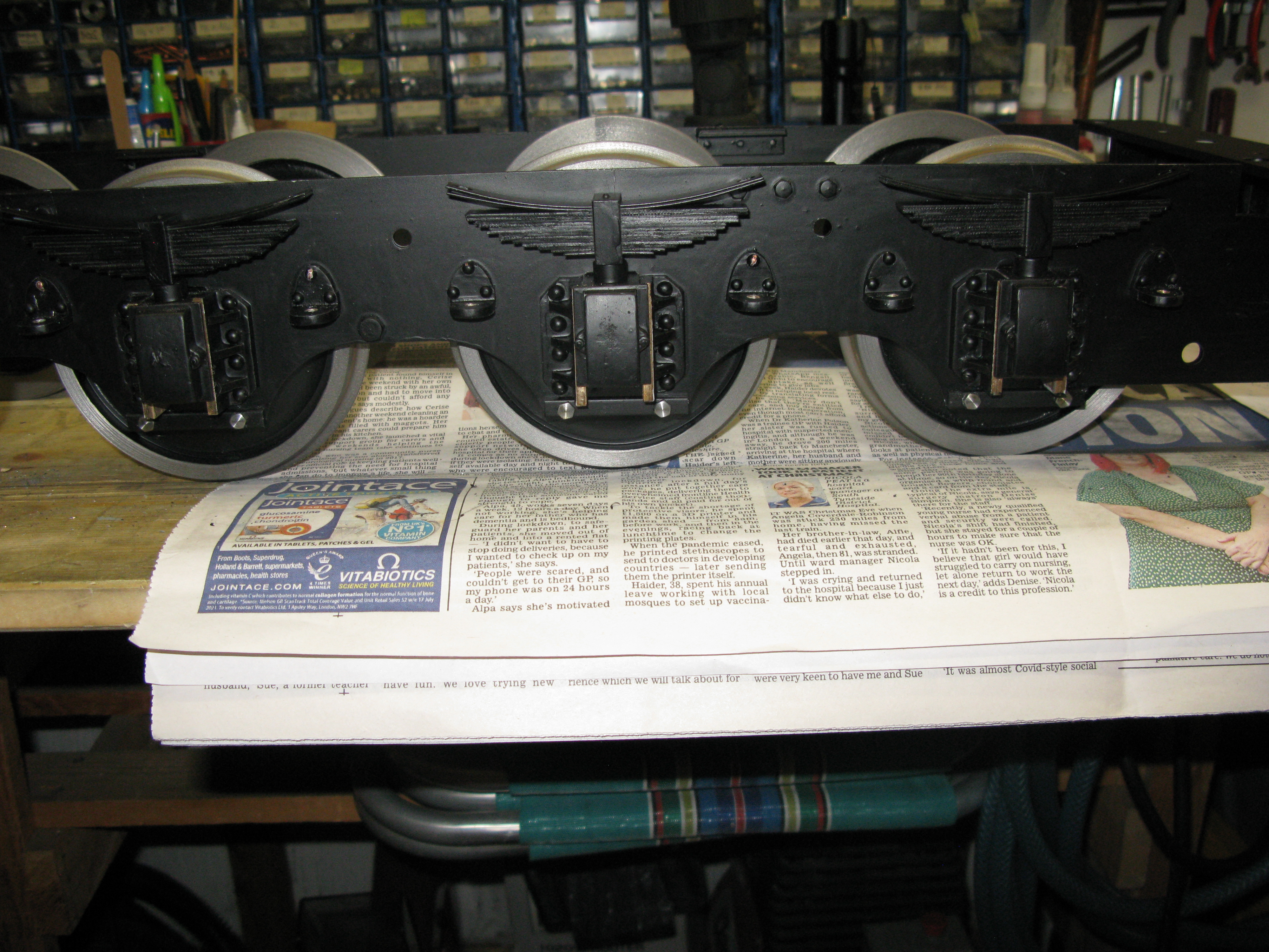
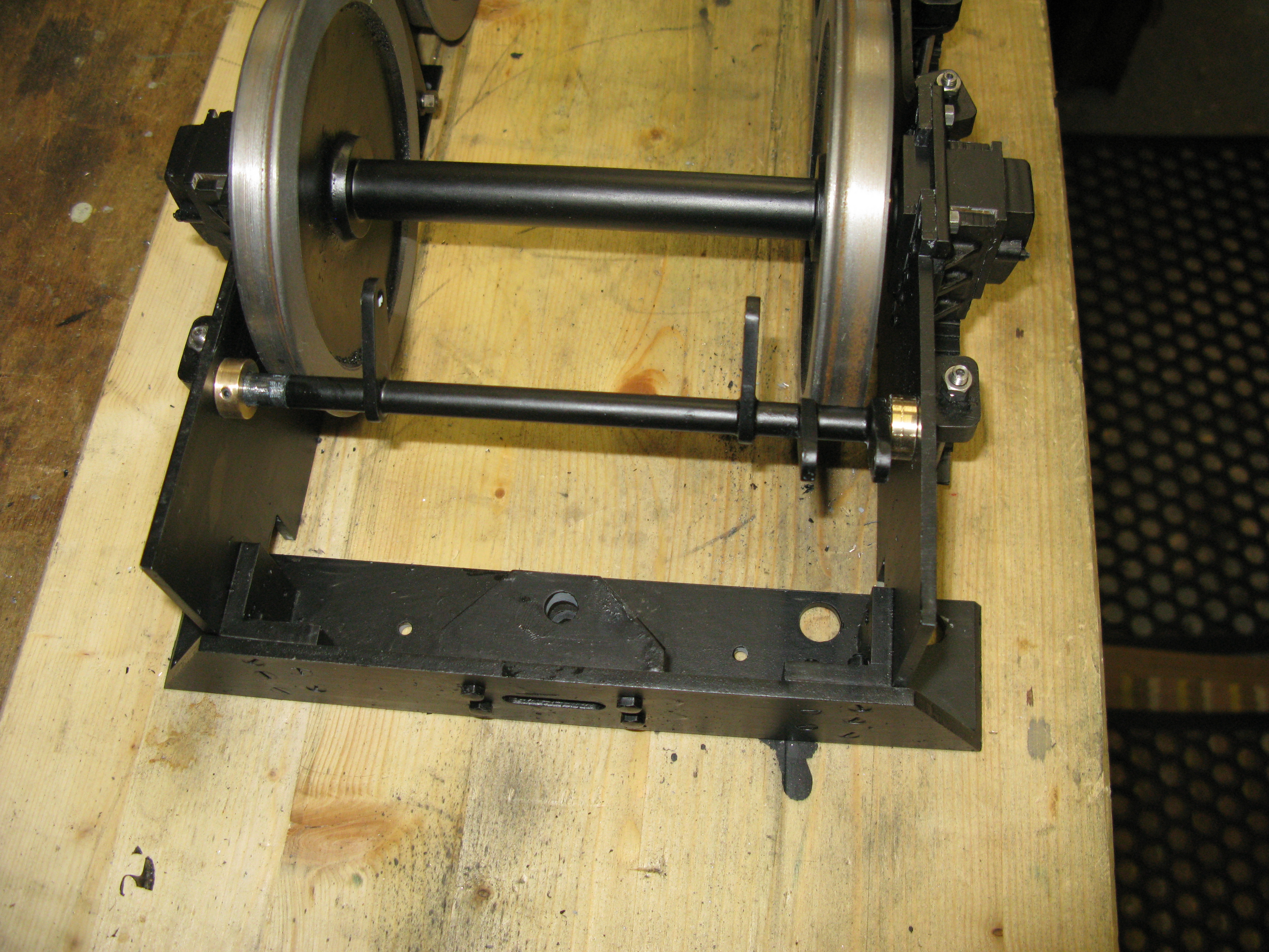
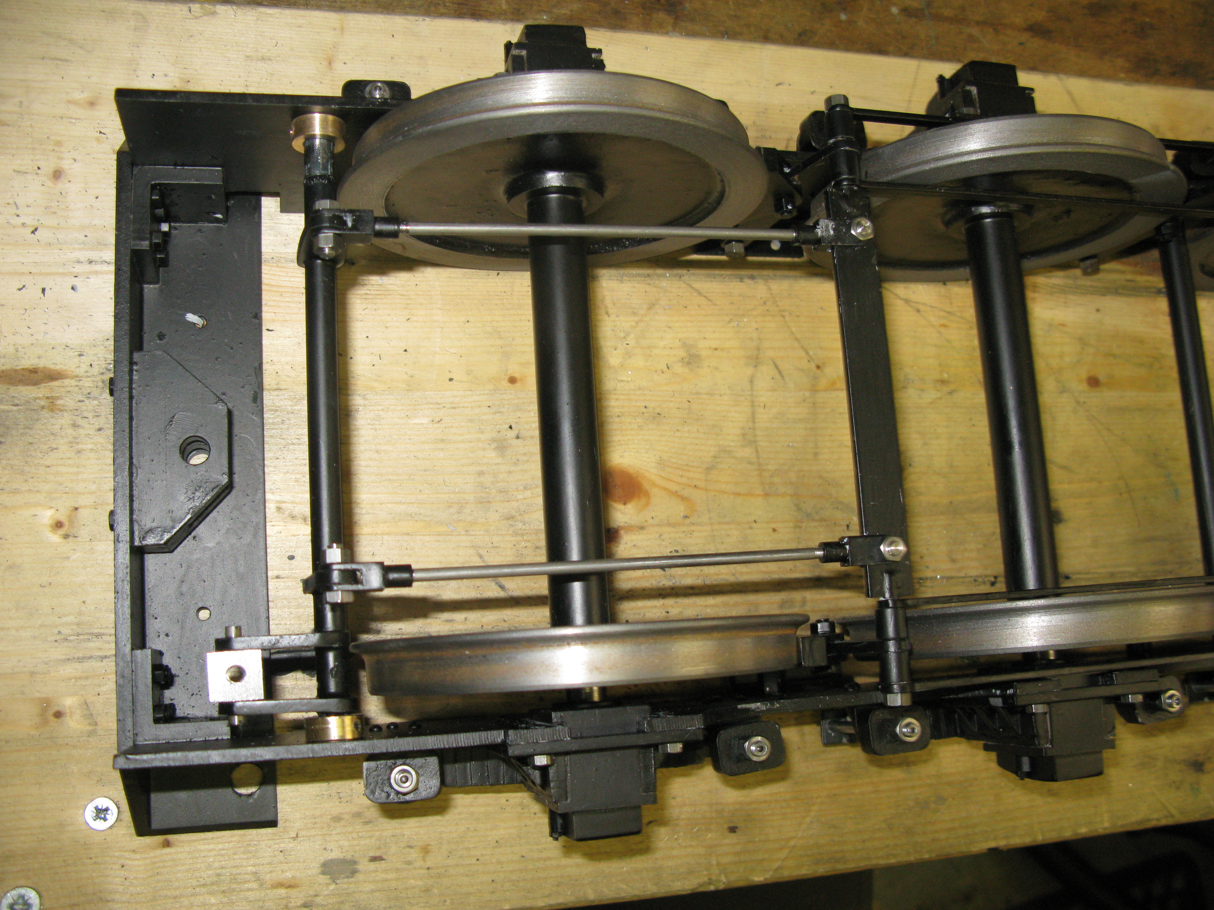
The fitted brake bars running either side of the wheels.
The brakes are operated from a tie bar which is just visible in the above photo on the left in grey undercoat. This is a flat bar 1/2″ x 1/8″ with 5/32″ diameter rods silver soldered into slotted ends which mate with the brake bars. This tie bar is connected to the oparating levers via 1/8″ rods with a clevis at each end.
Making the clevis’s is a multi step process. First blanks are made for the overall size and made over length to assist clamping when machining the radius end. Then the clevis slot is milled.

This is folowed by drilling the clevis 5/32″ hole and then radiusing the end.
Radiusing the end of a clevis.
The clevis is then mounted in a four jaw chuck in the lathe and the end turned down to the correct length and diameter and the 5 BA threaded hole put in.
The rods for the clevis’s are 1/8″ dia with a 5 BA thread on each end.
When all is finished the final connection to the brakes looks like this:
The brake handwheel and its staunchion will not be done until the tender superstructure is complete. Its threaded block can be seen in the photo above, It has a 2 BA drive and the pins are 5/32″ dia , 5 BA to allow it to swivel.
I think that completes the chassis apart from going around all the nuts and loctiting them in place which I will do once the superstructure is all but done.
