The various brackets that bolt to the outside of the frame are the subject of this chapter. Some are castings and others fabricated. They will be done as and when I feel like it and in no particular order but will eventually allow the footplate to be done, the wheel springing and main weighshaft to be tackled.
The first to be done is a simple casting for the footplate support at the rear bolting to the steam brake stretcher. It sits above the frame top and is naturally a right angled bracket with a 45 degree angle above the frame top.

Machining this bracket is relatively easy by clamping it down to the mill table and machining the right angle faces and then moving to machine the 45 degree face.
Having done this its fixing holes to the frame are drilled in the mill taking the measurements from the frame drawing.
Two brackets are done, one either side.

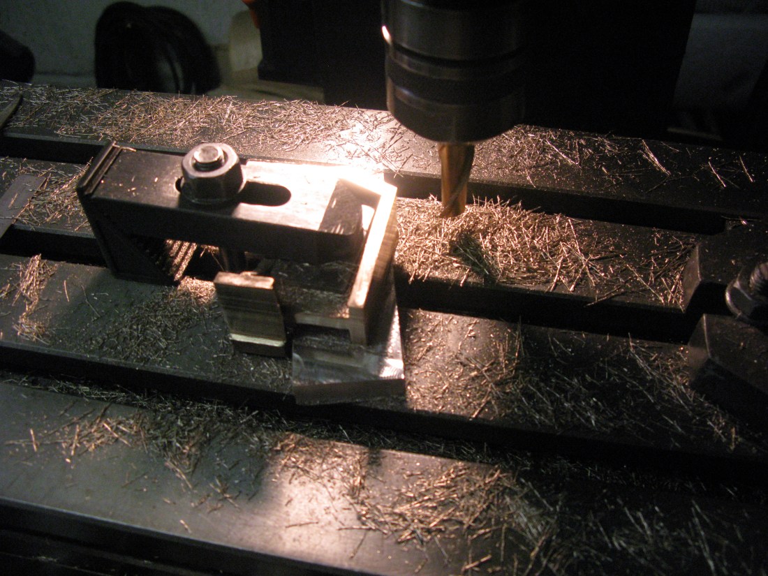
Expansion link bracket.
(Update from doing the running boards – this bracket needs to be modified to have a slope towards the frame at the top otherwise the correct prototype running board and as drawn running board cannot be fitted. Unfortunately much too late in the construction to find that out for me).
This is quite a complicated bracket and the castings supplied were not fettled so that job had to be done first.
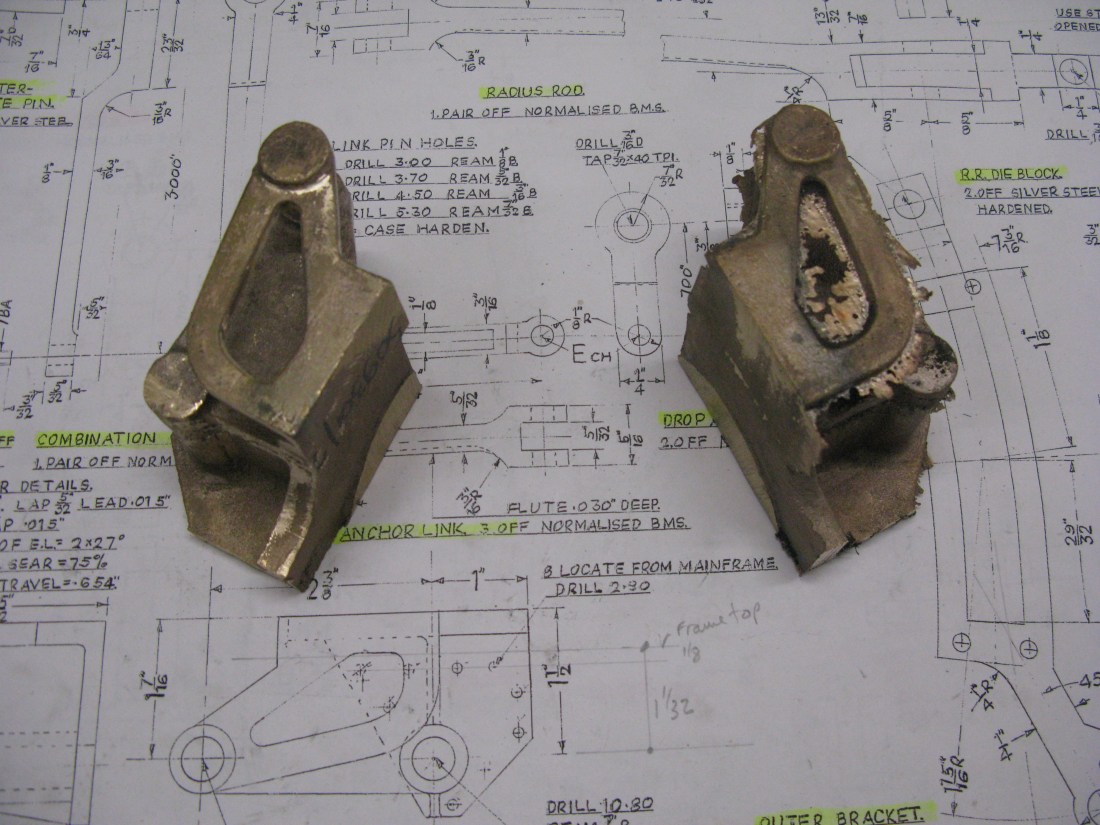 fettled and unfettled castings
The next job was to determin a reference side from which to machine subsequently. I chose the thin outer side (topmost in the above pictures) on the basis that it was close on the dimensioned thickness and that the side should hang vertically when in place. So this side was filed to give a flat face, apart from the boss, and this would enable its opposite side to be machined flat and parallel to it and to the correct width from the front. The machining of the opposite side was done by clamping the casting in the machine vice so its outer side was laying flat on the machine vice base.
The next important reference points are the centres of the two bosses. These have to line up with the frame holes and set the reference from which the height of the bracket is determined. They also determin the level of the bracket with respect to its top. The two bosses were painted in spectra marking fluid and the centre of the weighshaft boss established first. The horizontal centre line of the expansion link trunnion boss was then established and marked and finally its vertical centre line measured from the weighshaft centreline.
The casting can now be set up for machining the top using an angle plate to mount it upon. To get the casting level a height gauge was used to set the centre height of the trunnion boss centre line 1/16″ above the centre height of the weighshaft boss as called for on the drawing.
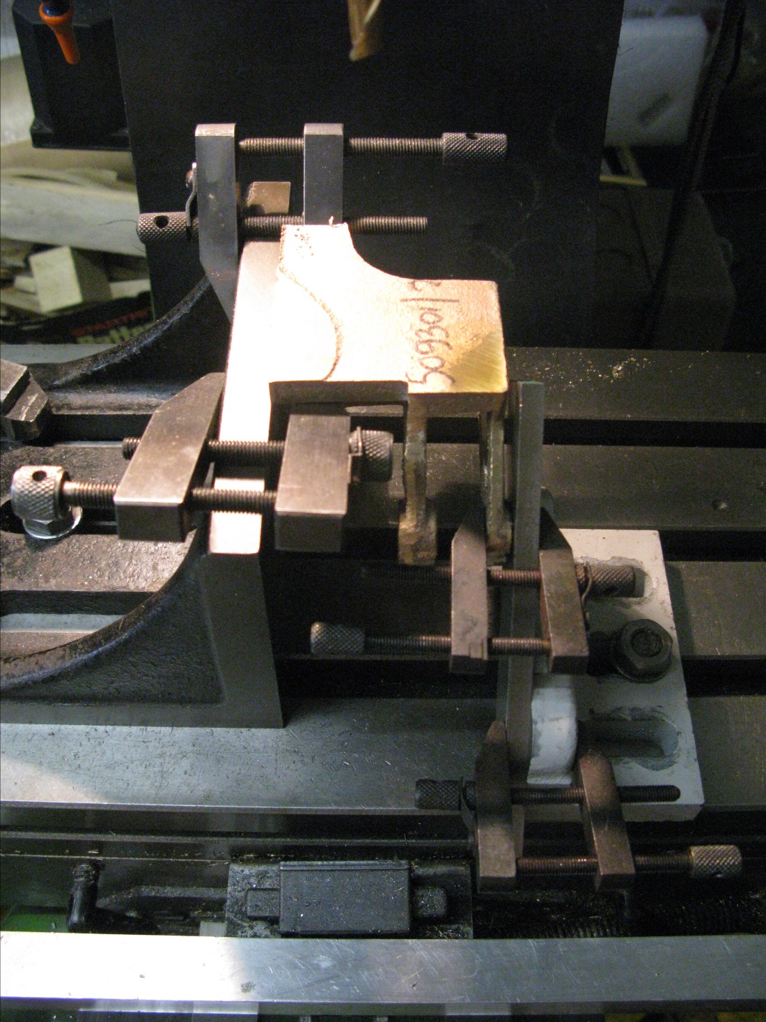
Set up for maching the top using an outer clamp to ensure rigidity
The top was machined down to be the correct height above the weighshaft centre line as dimemsioned on the drawing and checked using the height gauge.
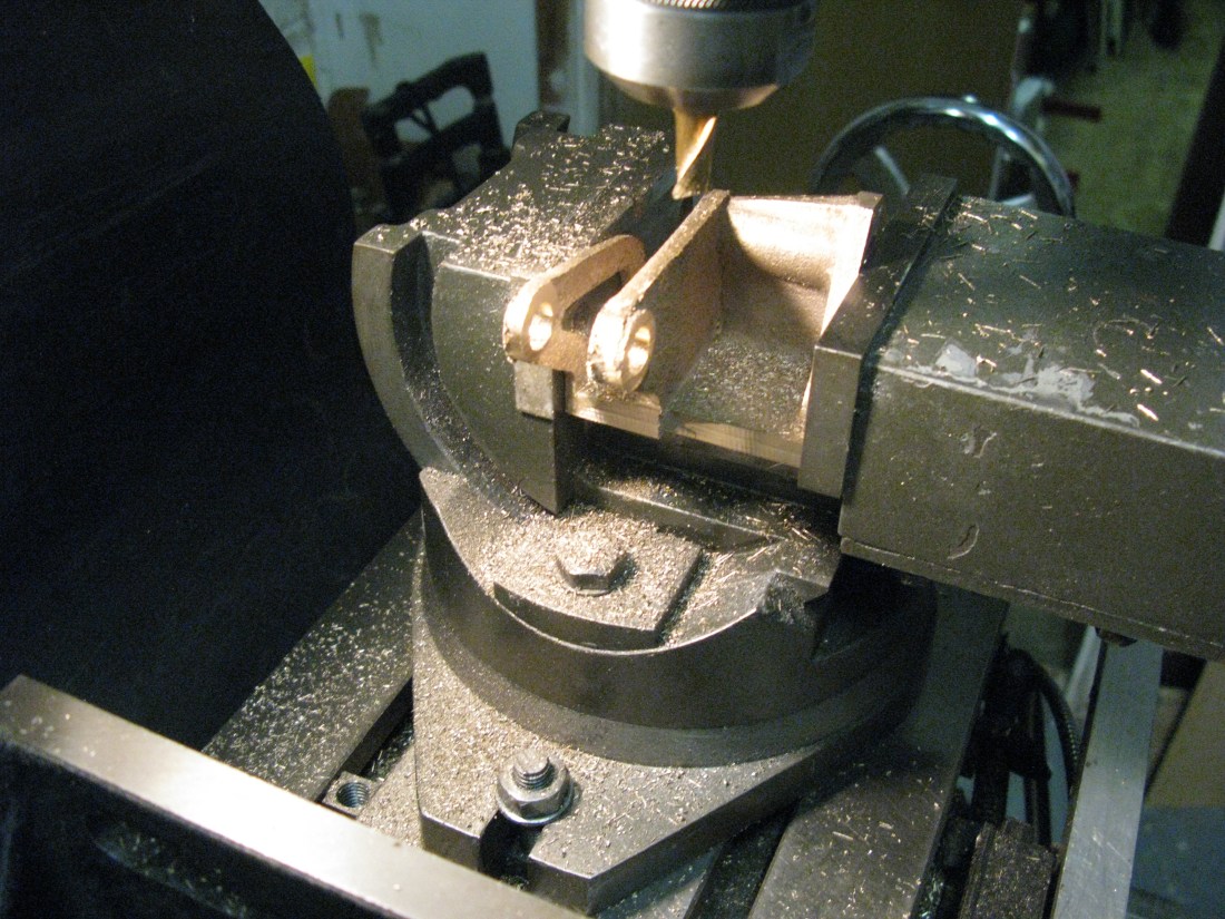
The trunnion and weighshaft holes were drilled next and reamed 7/16″.

Trunnion and weighshaft pilot holes drilled. A steady being used to resist drilling pressure
The first to be done was the weighshaft hole its horizontal centre being picked up from the angle plate (top of the bracket) and its vertical from the marked centre line. From this using the DRO the trunnion hole centre could be established.
The last holes to be drilled are the fixing holes. The measurements for these were taken from the frame drawing.

Fixing holes drilled with three centre drillings in error!
The casting was centred on the weighshaft hole as a reference. The DRO was then used to locate the frame top datum from which all the fixing holes were vertically dimensioned with their horizontal dimensions taken from the weighshaft centre line.
A trial fit to the frame showed all but one fixing hole lined up. The odd one out just required a clearance drill passing through the casting to correct the mild misalignment in the frame which must have occured when drilling the frames.
The gap between the webs was machined in the vice. The set up shown below.
The second casting was not quite so easy. The outer limb was slightly twisted in both vertical and horizontal planes. A bit of brute force obtained a mild correction but more may have broken the casting so no more was tried and machining went ahead as before. This resulted in the inner boss of the outer limb forming the trunnion bearing being machined away so the limb became flat all the way through on the inside. I do not think it will notice once the expansion link is mounted in the bracket (I hope).

Two expansion link brackets fitted.
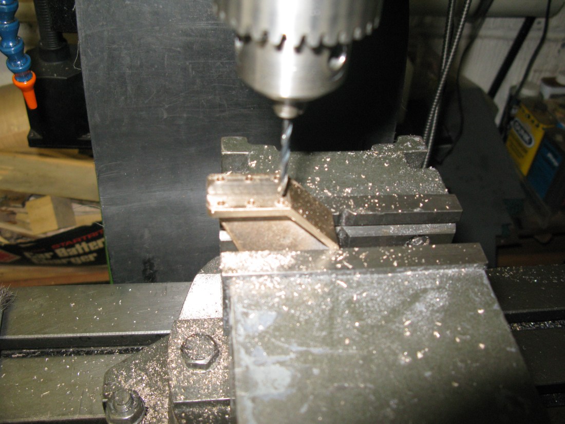
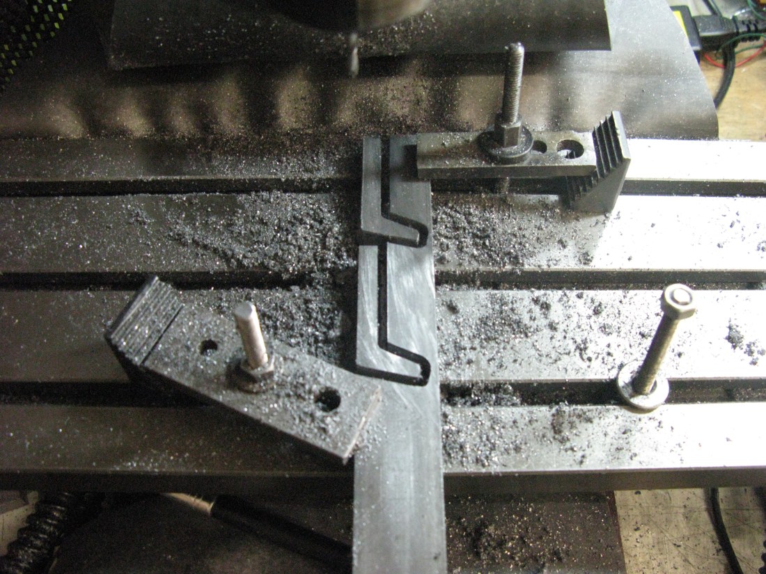
Slide bar bracket
Every now and then a casting gets supplied which no matter how you try it becomes impossible to machine it to obtain the correct dimensions without something being thick or thin at some point. This casting was such example.
On the face of it there was plenty of material to be machined away but on checking the various measurements I could not get all the webs to the correct thickness and get the slide bar mounting web at the correct distance from the top or the face bolting to the frame. So I had to compromise somewhere and this was done on the angled part of the web which ended up thin at one end. Hopefully this will be unseen under the footplate work.
Maching the slide bar bracket
To machine the bracket it was clamped to a piece of sacrificial material and a light skim taken of the top of the web to get a flat surface and then turned over to skim again to obtain a 3/4″ high depth. There was a minimal amount to be taken off the casting to achieve this. The top and side were then milled square to obtain the web thickness of 3/16″ approximately given the inside of the web was still a cast surface. The ends of the webs were then machined to the correct dimension as measured from either the side or the top. The underside of the slide bar fixing was rough machined as this had to be machined at an angle later.
The bracket was then removed in order to mark off the points where the angled part met with the top and side. The bracket was then remounted for milling ensuring the two marks were parallel on the table so the angled web could be machined.
The bracket was next mounted in the vice and set at an angle of 1 degree 9 minutes ( or as near as I could establish with my combination square). Bearing in mind this will establish if this is a left or right hand bracket I marked the bracket with an L using a marking pen to ensure I did not make two the same! The machining of this surface gave the correct dimension from the top face of the bracket as drawn. Finally this rectangular surface was milled square, the width being dimensioned on the drawing but its length was not and was therefore measured from the full size drawing.
The rear facing web that bolts to the frame is cut away at an angle at the bottom. The angle starts at 3/4″ from the bottom and finishes close to the vertical web so it was just a matter of marking this off on the casting and setting the bracket in the vice to make the marked line parallel to the table and machining it flat.
The last operation was to drill the fixing holes. With the bracket in the machine vice a datum was set as the top of the bracket and the top row of holes spotted as per as drawn dimension. From this point the remaining holes could be set out as per the frame drawing.
The second casting had similar dimensional problems as the first but slightly worse. It was not possible to get the plate to which the slide bar fixes in a position that would enable it to be machined all round without making the web affixing the bracket to the frame undersize. My solution to this was to machine the inner edge of the plate flat and silver solder a piece of 1/8″ brass to its edge to make it wider and thus be able to be machined to the correct width.

Slide bar brackets fixed to frames
Spring Hangers
The spring hangers are fabricated from two pieces, the leg and the plate which attaches it to the frame. Two hangers are shorter and bolt to the underside of a stretcher rather than to the frame and the rear axle hind hanger plate is slightly shorter as well. So eight to make all the same and two pairs that are different.
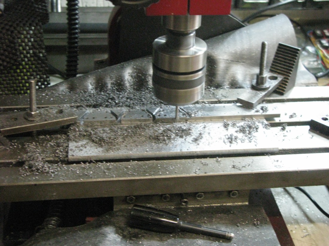
The hanger is an L shape with the bottom of the L at an angle the top and bottom of which are at different angles. They cannot be bent and have to be machined so I resorted to my little CNC mill again to make them.
Five hangers can be machined out of a 12″ length of 1″ x 1/2″ bar, four long ones and one short one. Once the contour is machined to 7/16″ deep the bar is removed and 1/16″ milled away to leave the hanger free of the stock bar.

The legs all machined and drilled – just the plates to do next.
Sharp eyes might notice the third one up on the right has a black end. A slightly over enthusiastic adjustment on the mill caused a rogue movement. It is shallow and filled with epoxy metal filler.
All the legs are drilled next for the spring hanger bolt and then the top is milled away 3/16″ deep and 11/16″ long to accept the plate.
Onto the plates. Eight are the same, then two slightly different (they need to clear the rear frame stretcher) and another two totally different as they have to bolt under a stretcher rather than to the frame.
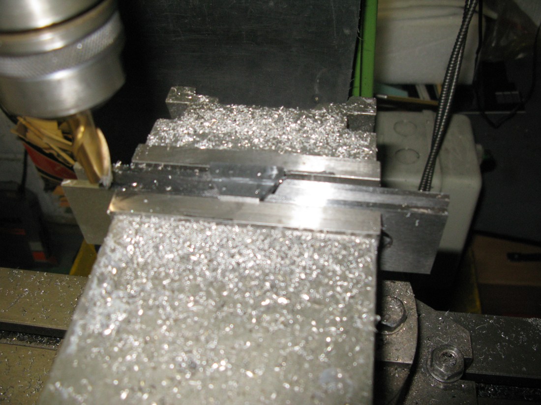
CNC machining the plates 8 off
The plates were machined in batches of three. Just a convenient size for the CNC and not taking half a day to do. The sequence was to centre drill the holes, then drill 3/32″ and then slot cut. The stock bar is 3/16″ thick and the plates are 5/32″ so all the machine operations were down t0 5/32″ enabling more than one to machined at once. The block of three were then broken down into single units to have 1/32″ machined off the underside. I did try doing all three at once, see the photo below, but it did not work because an individual unit would break free under the cutting forces when reaching the correct depth as can be seen in the photo, the right hand end one has tilted up.
The finished set of components are seen below:
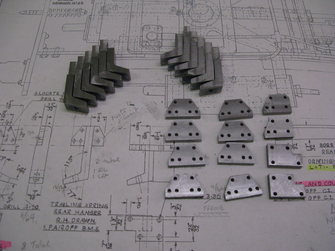
Eagle eyes might notice that the two at the top right which have the right hand edge cut away are not exactly as drawn. The reason for this is that when I drilled the frames the holes had to be measured from the drawing as no dimensions were given on the frame drawing. I wrongly assumed the holes on the right hand side of the plate were a mirror image of the left hand side minus the extreme right hand hole. Not so. The inner right hand hole is set further out. As a consequence to avoid having half a hole on the right hand edge I cut a liitle more off to give a clean edge making it slightly narrower in width.
Next job is to silver solder the lot.
However before silver soldering the front axle rear hangers I used the plates to jig drill the stretcher to which they fit. Had they been silver soldered one of the holes could not be jig drilled as the leg bend prohibits a drill getting to the hole. The holes were drilled and tapped 7 BA.
In order to get the plates in the right place for jig drilling the centre line of the leg was first marked on the leg (at right angles to the frame) and the centre line then marked on the frame 2 3/4″ from the edge of the horn block to match the same measurement to the front hanger.

A coat of undercoat on the cleaned up hangers was applied and then they were bolted to the frames with 7 BA c/s screws.
I then found that the trailing hanger on the rear axle needed a minor modification. The leg sits 1/32″ proud of the frame inside edge and the trailing hanger on the rear axle is at the position where the frame angles down so 1/32″ had to be taken off the leg to match the frame contour.

All the main spring hangers in place
The trailing wheel spring hangers are cast as a single block in gun metal and I simply machined the right angled edges on the mill as one block to clean them up.
The individual casting is not particularly good in that their shape is slightly undersize and the individual hangers not uniform about a centre line thus making the finished hanger look somewhat awkward. The fixing holes come quite close to the edge and the spring hanger hole does not appear on the apparant centre line although it is on the centre line of its right angled side because of it lop sided shape. Fortunately they are not really visible and being painted black they will hopefully blend into the background.
The hangers are fixed to the frame by 8 BA round head screws unslotted to look like rivets.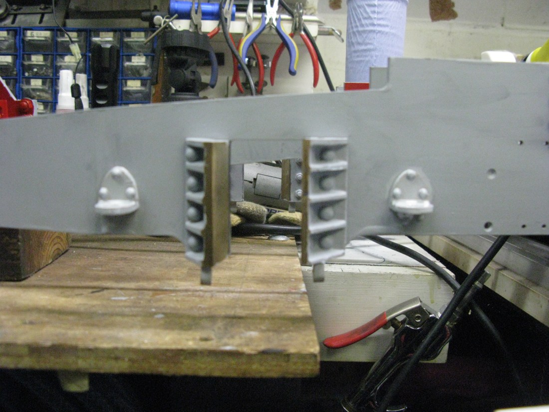
Trailing wheel spring hangers in place
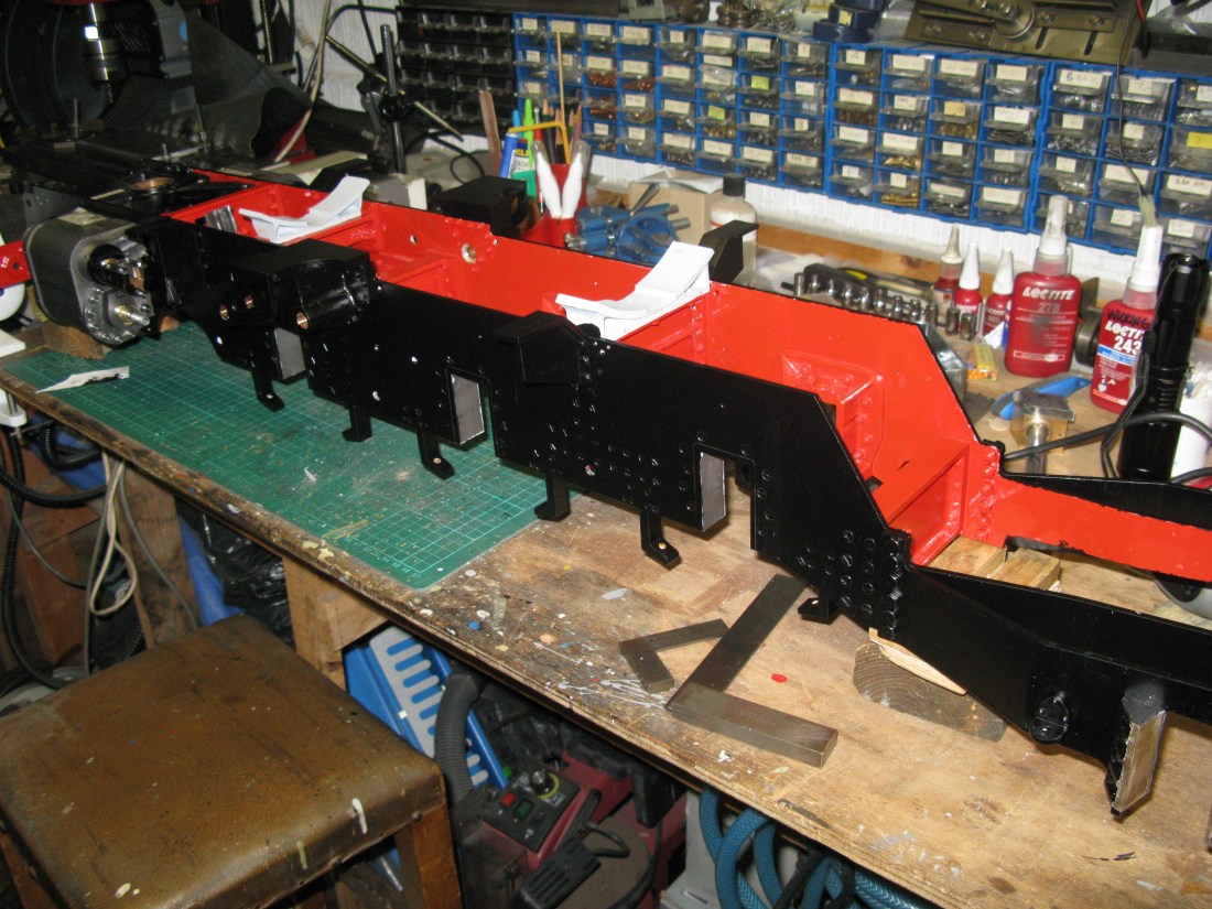
A coat of satin black now on the frames.
