The K exhaust is a bronze casting. It bolts to the inside face of the inside cylinder block and onto both frames. The frames have two rectangular holes each which match up with the K exhaust which takes the steam exhaust from the outside cylinders and also the exhaust from the inside cylinder and passes it to the blast pipe.
The frame drawing omitted the fixing hole details so these will have to be drilled in situ with measurements scaled from the drawing.
The first job is to machine away the casting draw (taper) to achieve a truly set of square faces from wich to work.

Machining the casting draw away
Having done that the sides can be milled down to give 4 1/8″ between them to fit in the frames (there is no gasket) and front just milled to be square with the sides.
Next comes the tricky bit. The casting has to be mounted on the mill to machine the mating face with the cylinder block at the correct angle so when fitted the top of the casting is level with the top of the frames. I used an adjustable square to get the exact angle of the block aginst the frame and then transfer this angle to set up the work on the mill.

The mill set up used the angle plate packed up at the back end to achieve the correct angle for milling the face.
The next task was to bore out the hole that slides over the valve liner and then drill the hole for the exhaust to pass into the upper channels.
The fixing holes for the screws to mount the exhaust to the cylinder block were all drilled with the same set up.
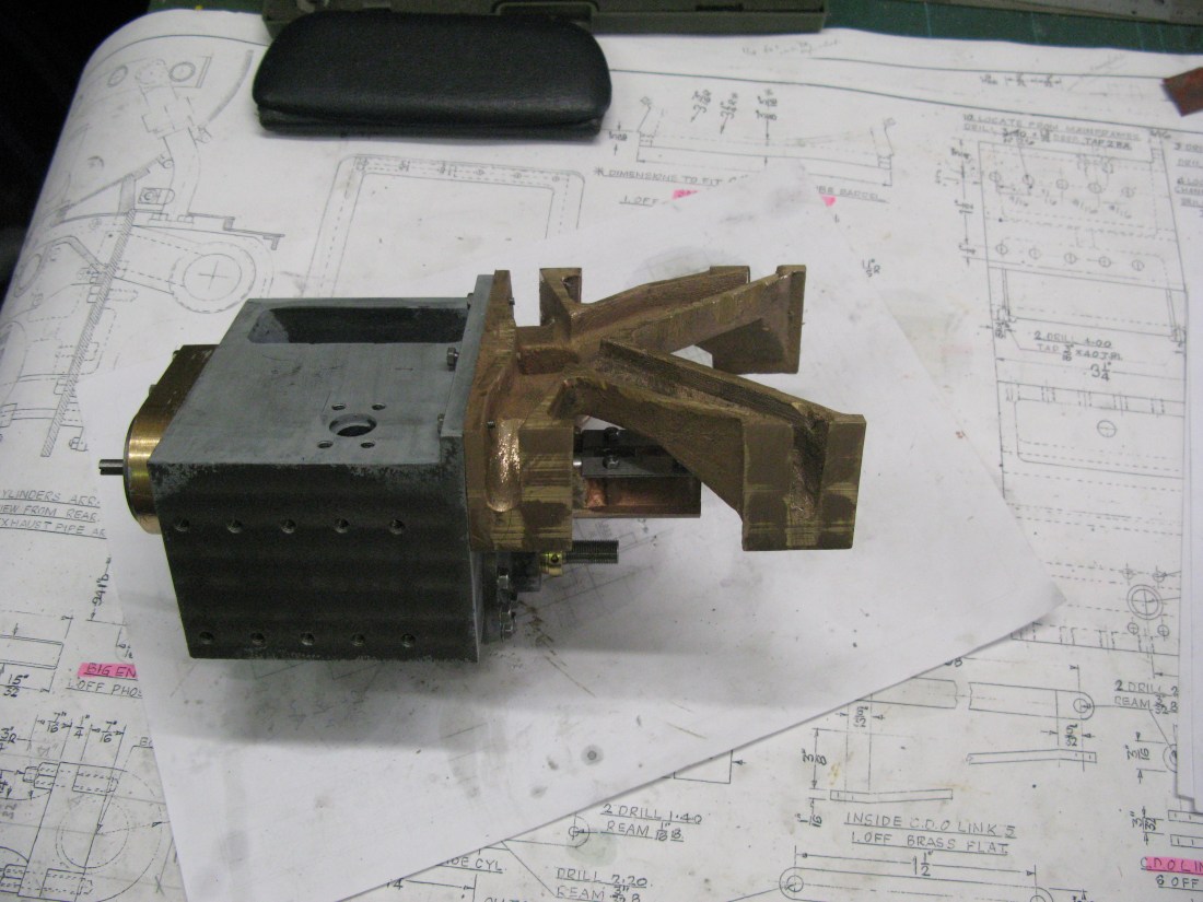
A trial fit onto the piston block established all the holes lined up.

A trial fit of the assembled block into the frames checked eveything lined up as it should.
With the block still in place the frames were marked out to drill the fixing holes for the K exhaust that had been missed off the frame drawing. The measurements were scaled from the drawing. The frames were placed on the mill table and the fixing holes drilled for 6 BA tapping. With this done the block and K exhaust were removed and the K exhaust fixing holes tapped 6 BA.
The last machining job on the K exhaust was to machine the top down to be level with the top edge of the cylinder block but the top has to be parallel to the the frame top edge.

To do this a rather Heath Robinson affair of clamps and angle plates was used to clamp the block and K exhaust at the right angle on the mill table. The adjustable square set to the block angle can be seen below the blue clamp.
The casting has a 20g brass plate soldered to the top to cover the steam ways. This was simply marked out on a sheet of brass using the casting as a pattern and cut out oversize. It was soldered in place with high melting point (243 degrees) solder. The edges were then cleaned up with a file to match the casting. Interestingly the drawing shows a lip with the cover overlapping the cylinder block by 1/32″. Whilst I followed the drawing I do not know what the lip was for.
The exhaust steam exit is via a brass bush that is mounted on the centre line in the brass cover. The bush is drawn at 1 1/2″ in diameter and 7/32″ high with a spigot turned at 1 3/8″ x 1/32″ wide to fit into a matching hole in the brass cover. Although the bush is drawn on the cover the spigot diameter is not shown. Had it been, it would have been obvious that at 1 3/8″ diameter it was dangerously close to braking through the casting wall. So I chose to make the spigot at 1 1/4″ diameter. The boss has to be tapped 1″ x 26 tpi. I had no desire to purchase a tap of this size for a one of application and decided to screwcut the thread.
The hole in the cover was machined on the mill with a boring head and the boss fitted and soldered in place with the same melting point solder as the cover.
The completed K exhaust
An update following work on the outside cylinders. The K exhaust needs to be fixed to the frames with countersunk screws to allow the cylinder block to fit flush to the frame.
