This chapter will cover miscellaneous items in the cab which are not covered elsewhere.
I’ll make a start with the reversing stand. The reverser is a vertical stand with a screw thread operating the bell crank to the reach rod that goes to the expansion link lifting lever. It also has an indicator to show the amount of cut off.

The basic reversing stand assembled.
The two holes at the top take bearing inserts for the bearing head holding the reversing handle. This allows the head to rock taking up the radial movement of the bell crank that attaches to the bottom of the reversing handle screw sheath connecting to the shaft that goes through the three holes at the bottom.
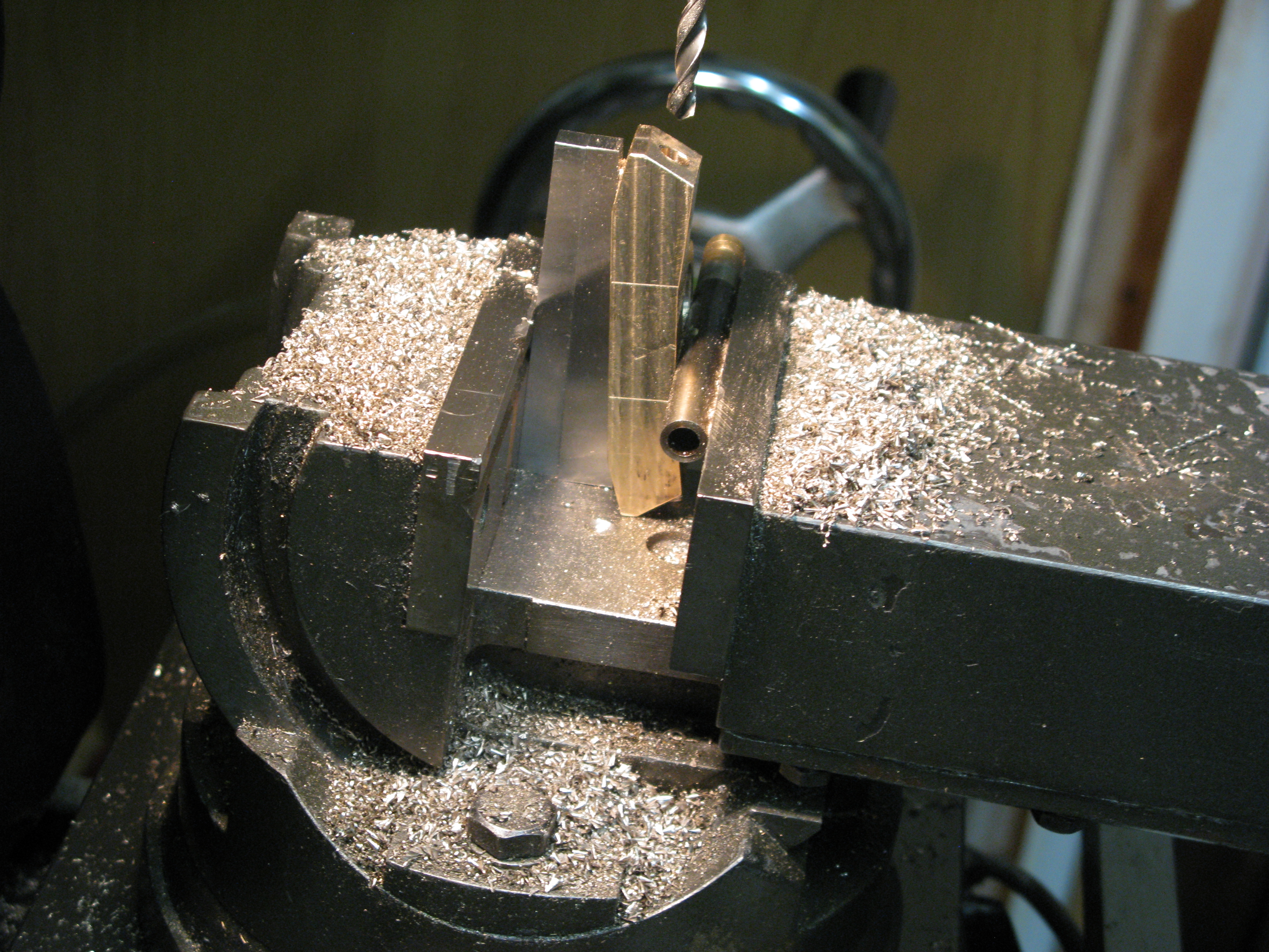
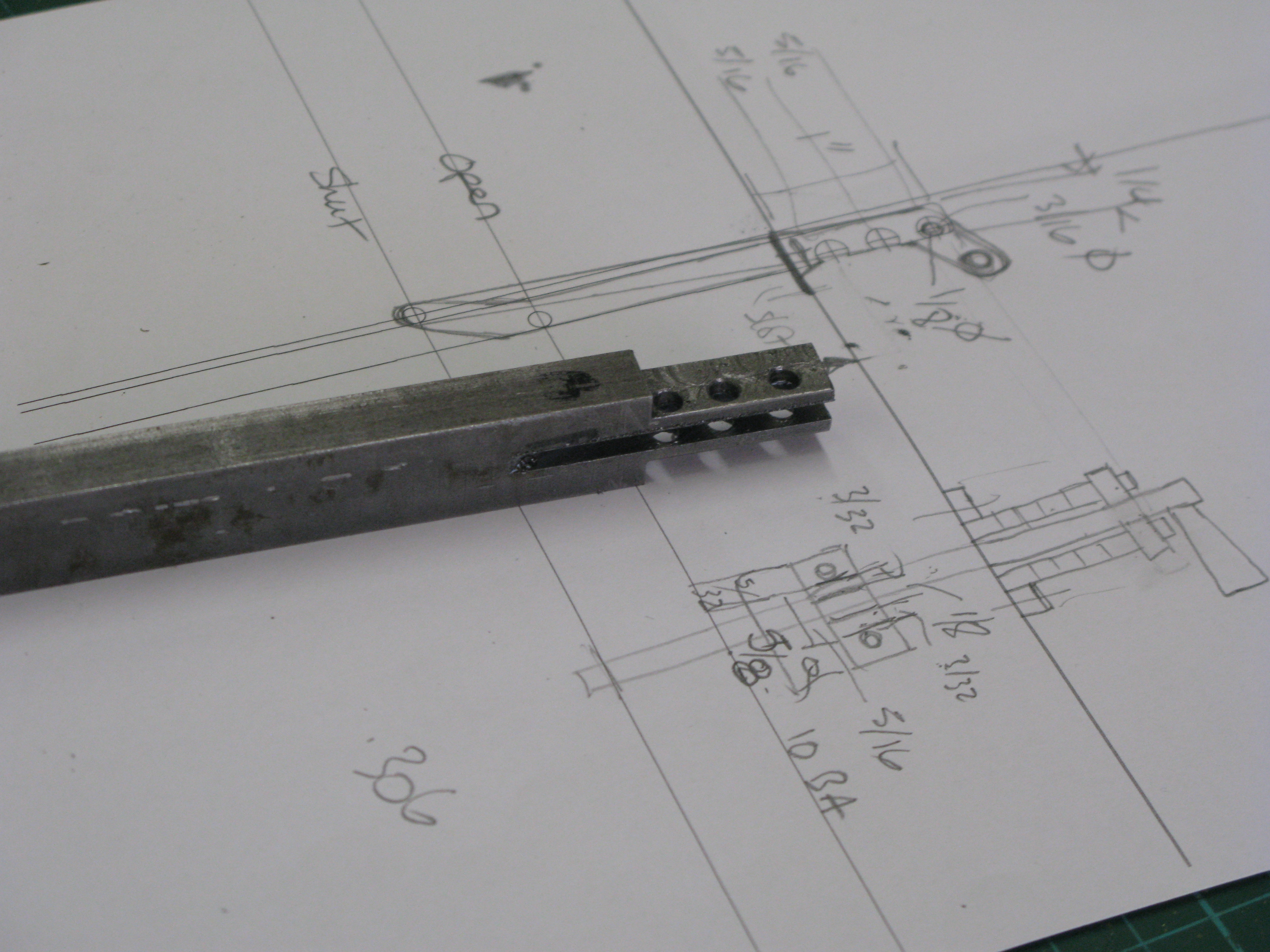
The reversing handle screw is drawn as a left hand 1/4″ whitworth thread. This is 20 tpi and I decided to increase the “gearing” by using 0 BA which is 26 tpi and only a few thou smaller on diameter. The length of the screw to be threaded is 1 5/8″ and no taps are usually that long. So to tap the sheath that screws onto the handle I had to grind down the shanks to allow the taps to go to the full depth. I learnt that when grinding down the shank the top thread of the tap has to be as square as possible otherwise it takes the profile away from the the thread already cut.
Tapping the sheath which is 7/16″ square BMS with CS taps (HSS cost a bomb left hand) was difficult and I had to use all three taps, taper, number two and plug, to do a couple of turns a time and when the taps were half depth it was more a millimetre or less at a time. Eventually the full depth was achieved and no broken tap!
I have realised that the brake valve plate silver soldered onto the side is on the wrong side! blow! Fortunately it is not important and does note interfere with anything. A new plate can be bolted on the correct side later as the stand is now all painted.
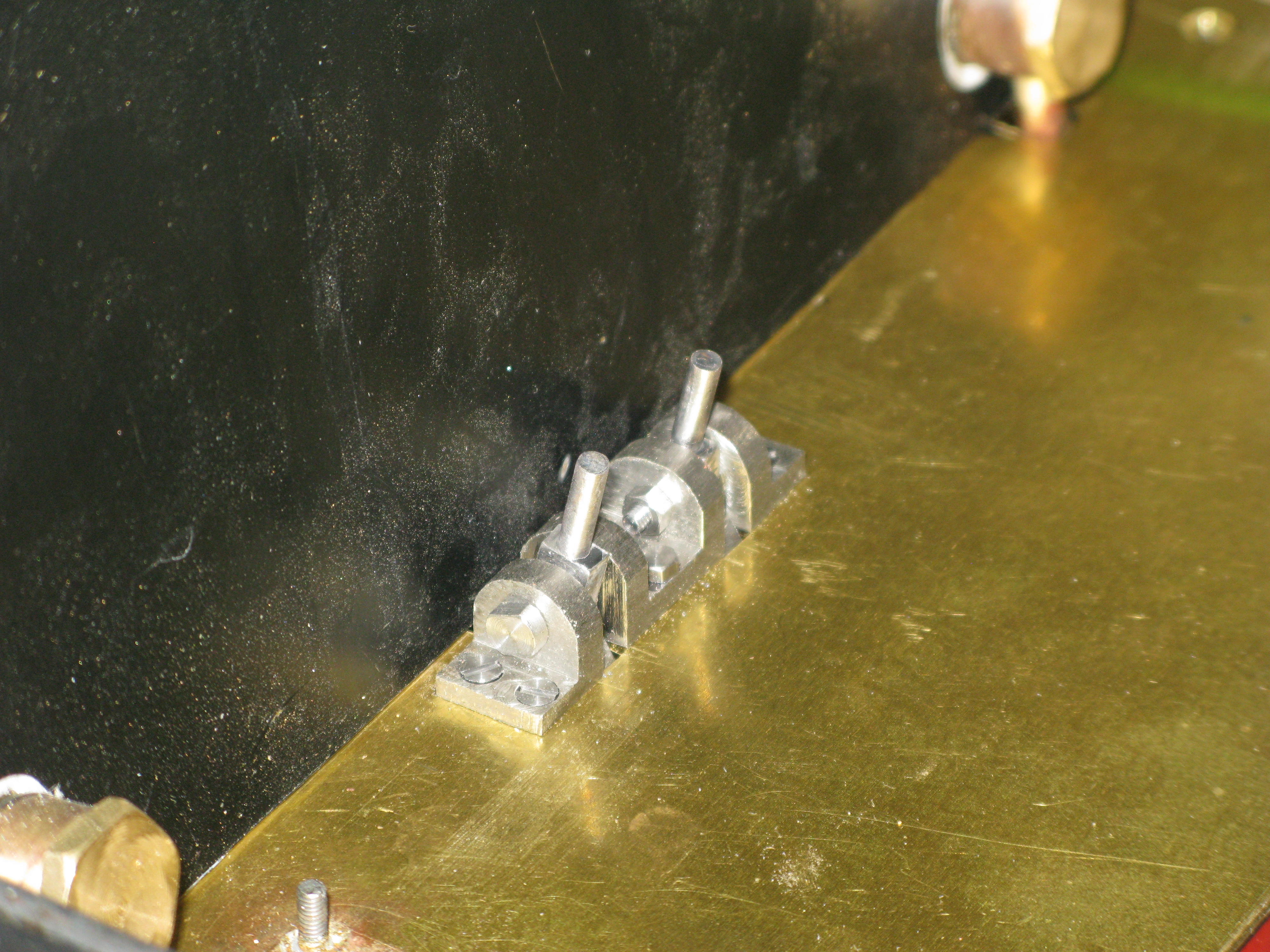
The connecting lever to the pin which drives the reversing rod lever is made and as the drawing showed no means of securing it the pin I have used a split collet arrangement to bolt it up tight. This can be seen in photo below with the head of the clamp bolt showing
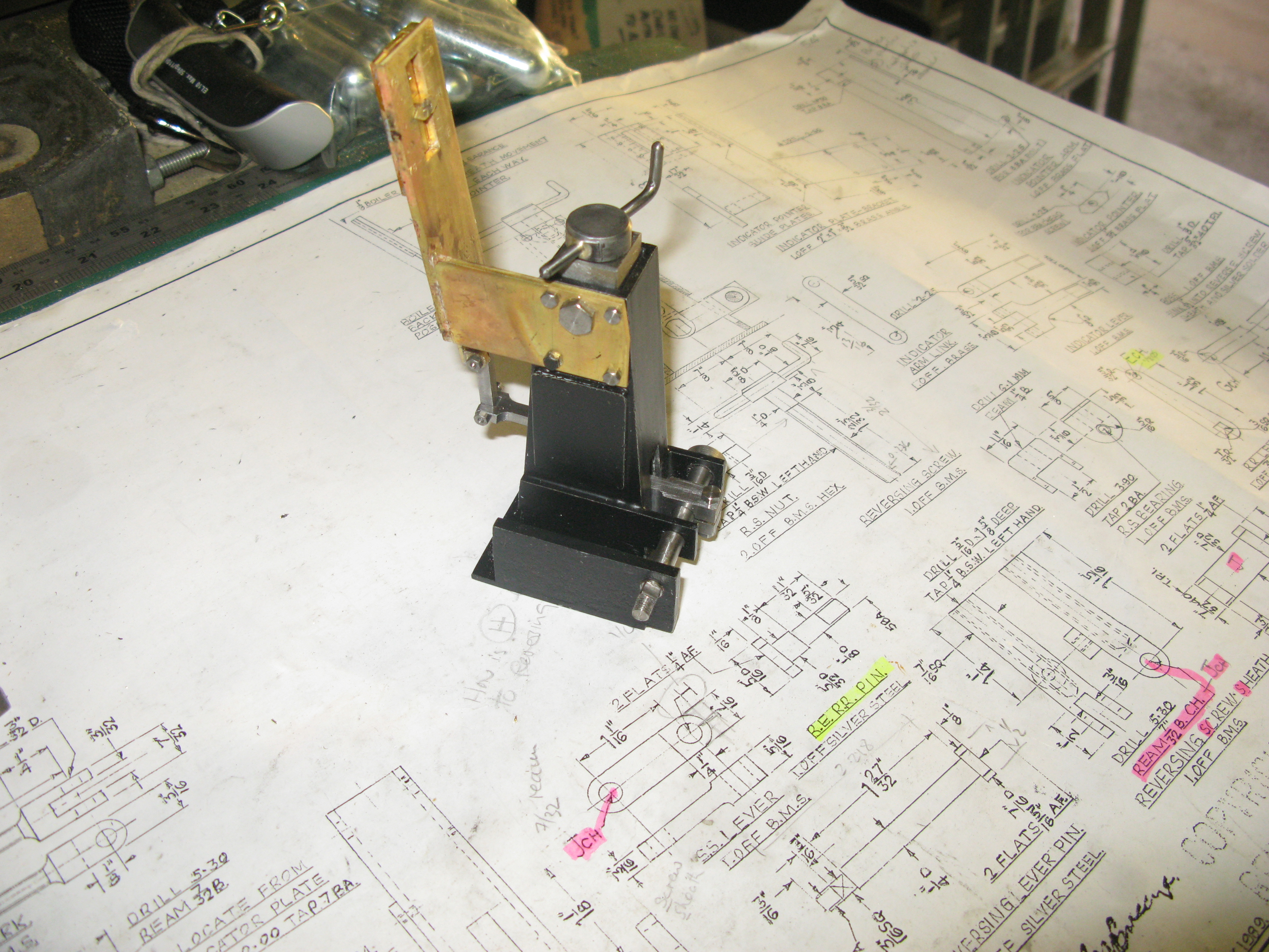
The reverser indicator is a slide bolted to the side of the stand as can be seen above. It is driven by a lever screwed into the reversing sheath.screw inside the stand and thus goes up and down. This lever connects to a slide which shows a pointer in a cut out window.

The two photos show the assembly before the indicator is cleaned up and given a bit of a polish.
There were a couple of minor niggles to resolve in assembly, the pointer is shown screwed to a standoff fixed to the slide. This standoff obviously fits in the window but of course the slide cannot be assembled in its runners as the stand off then fouls the assembly. The solution was simply to make the pointer and standoff as one unit and bolt that to the slide once the slide was in position. The other was that fortunately I had checked the distance between the slide link pins before making the link only to find it did not match the as drawn dimension. Only a 1/16″ out but that was enough to make the pointer off centre when the reversing screw was halfway on its travel.

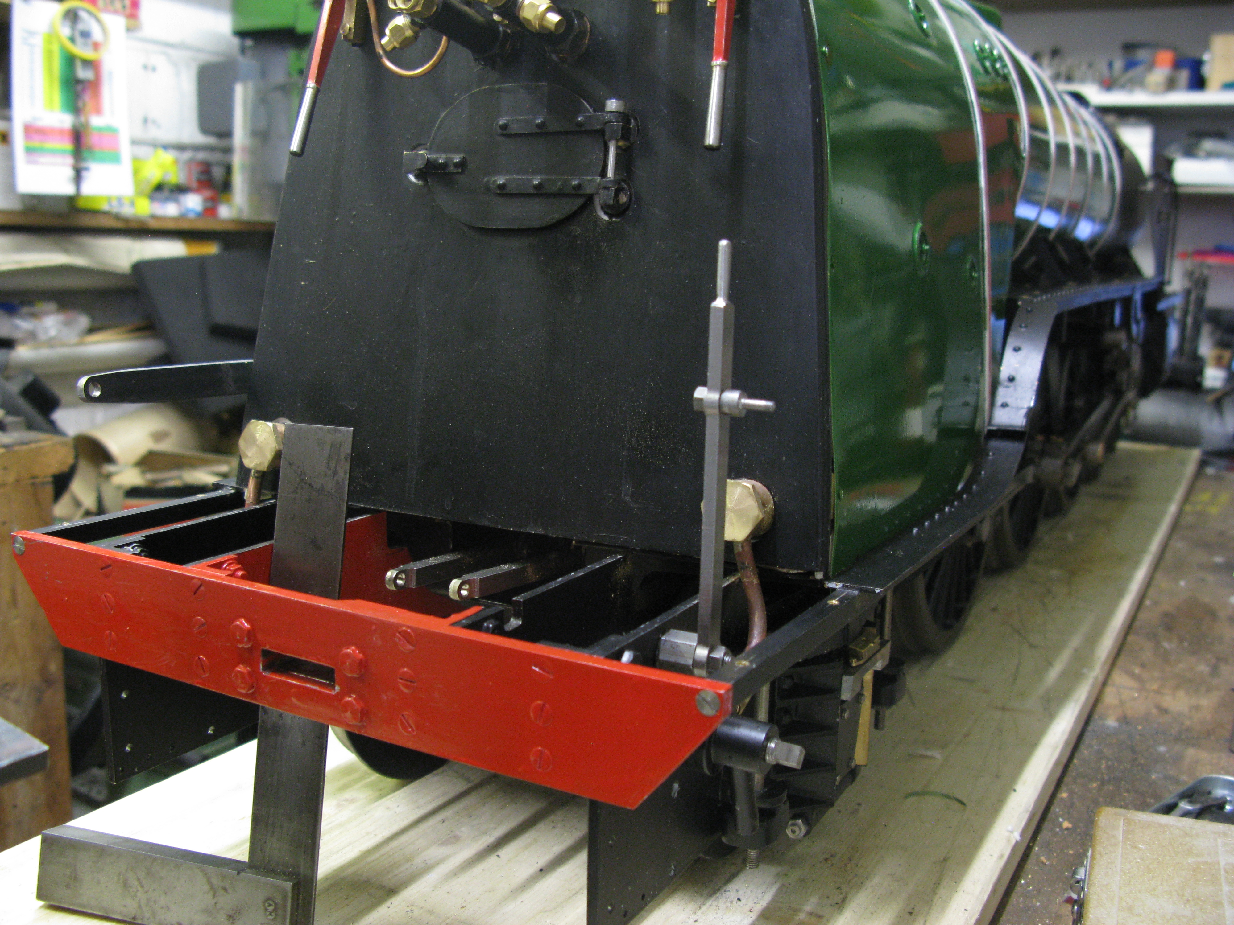
The finished (almost) stand in its rough position on the cab floor. It will not be fixed until the reach rod is made and trial fitted so it can be positioned accurately. The reach rod lever has yet to be made and also the drivers brake valve which is fitted to the right hand side of the stand has to be made and fitted.
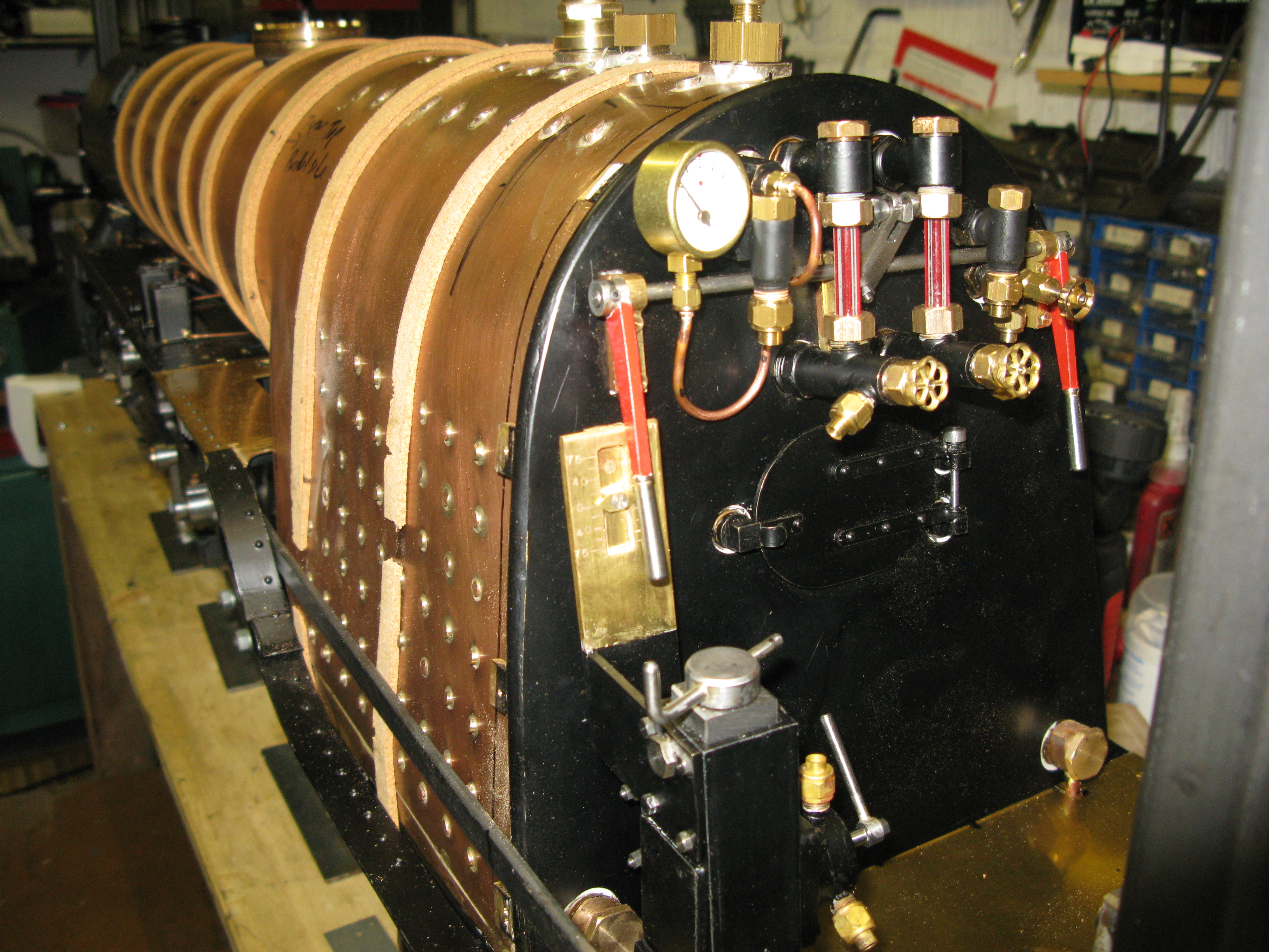
Looking at the full size A1 (Tornado in particular) it is clear that the cab arrangement on the Breeze design as can be seen above is not large enough as there is no room for the drivers seat behind the reversing stand. I do not know if this is an error in the boiler design or the frame length. This is a dissapointment as if the boiler is too long then the cab will not look right in respect of the window arrangement. Not much I can do about it at this stage.
The other thing that is noticeable is the height of the fire hole door. It is much lower on the full size. I think the boiler design is at fault here.
Back to positive thoughts ……… the blowdown hole in the boiler behind the reversing stand will have to have a banjo coupling designed with an exit through the cab floor to a blow down valve beneath the running board. Just another little thing to keep the grey cells active.
Update ….. Found some works drawing which shows the cab very similar to the as drawn design. So the full size A1 Tornado must be to a different specification. The drivers seat is shown on a slim pedestal positioned right at the back of the cab floor, level with the rear edge of the cab side wall. So that seems to resolve that worry. Cannot find anything about the backhead and firehole door position though.
Reach rod
The reach rod as drawn is only 1/8″ x 5/16″ which I felt was too flimsy so I increased the depth of mine to 7/16″ which happend to coincide with material I had to hand! There is nothing special about the reach rod and its two connection pins (made from silver steel) other than I had to put a slight set in mine to clear the added footplate bracket that I put on that was not on the drawing but does exist on the full size.
There will be a support bracket to be fitted to the foot plate bracket that about mid way along its length this gives restraining against potential bowing. This is not shown on the Breeze drawings but does exist on the full size.
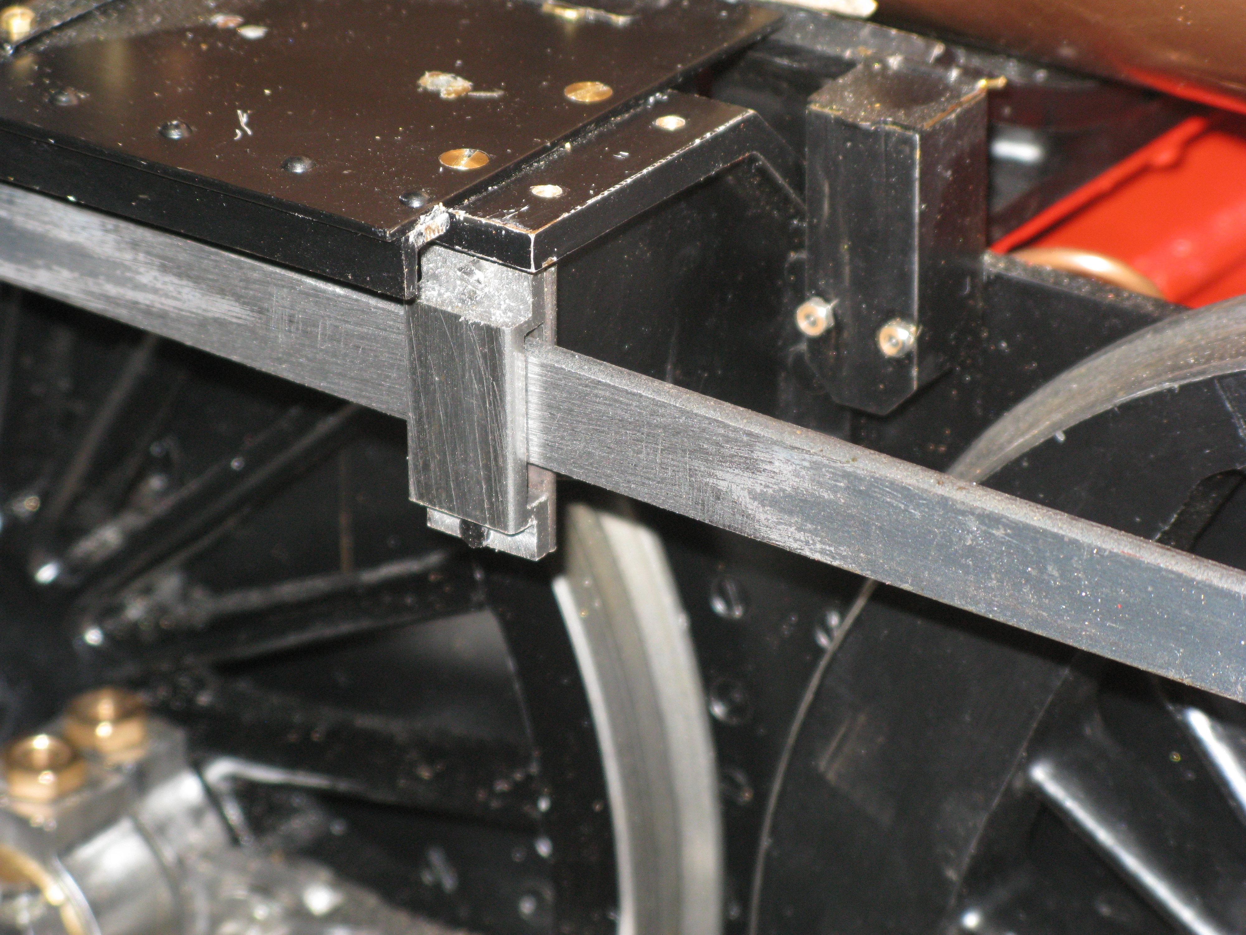
Support bracket for reach rod fitted in place
The bracket consists of a rear plate 1/16″ thick which is bolted to the running board bracket at the top by an 8 BA screw and two thirds of the way down by an 8 BA C/S screw as the bracket extends lower than the running board flange. The U shaped cover is machined from solid and uses the same 8 BA screw at the top and another at the bottom.

Having made the rod I decided to finally fit the reversing stand in place to give it a try out. The reversing stand is fixed to the cab floor with four 6 BA c/s screws soldered in place from underneath as there is little access to get nuts on as the holes on the outer edge are very close to the inner frame.
The trail run was not a success. The valve gear and expansion linkage is far too stiff and the reversing linnkage slips on the shaft despite having the clamp nut as tight as I can reasonably get without risking shearing the clamp bolt. I was expecting this as the whole motion is stiff and is due to the three cylinders piston valve rings having high wall pressure. I am convinced of that. I shall now finish off the remaining fittings to get the boiler air tight and give it a run on air for a while to see if that will bed the whole motion in and give me a solution to the stiffness. If it doesn’t then its a strip down of the valve gear which I dare not contemplate having got this far.
Update…… The run on air was not much of a success as the regulator would not move under pressure. A firm knock was needed to make it move where upon the loco sprang into life at full speed! I decided to investigate the stiffness without any more running as I needed to find out why the regulator sticks under pressure.
I started the checks by dismantling the left hand eccentric rod and radius arm and found the valve radius rod was stiff in moving up and down the expansion link. This was cured by shimming the outside expansion link plates away from the expansion link. Hvaing made sure the radius rod moved up and down the expansion link freely without the eccentric rod connected I repeated the check on the right hand motion which turned out not bad at all.
I disconnected the radius rods on both sides and operated the reverser driving just the inside cylinder gear and there was no problem at all. That was a relief as it meant I did not have to take the boiler off.
I then reconnected the radius rods on both sides and tried the reverser again and it was fine. At this point only the inside cylinder valve is operating as without the eccentric rods connected the valve wil not move and the expansion link just swivels.
As soon as I reconnected the eccentric rods the stiffeness returned but not as bad. This I think proved the stiffnes is due to three valves being driven and so I am now hopeful that with a few hours of running the stiffness will dissapear.
Drivers brake
The drivers brake is the classic model engineers design of a disc rotating inside a housing that connects two ports out of three in each of two positions, so in one position steam is admitted to the brake cylinder and in the other position the brake cylinder is vented to atmosphere with the steam supply cut off. The body is a GM casting and the dsic and cover made from GM bar.
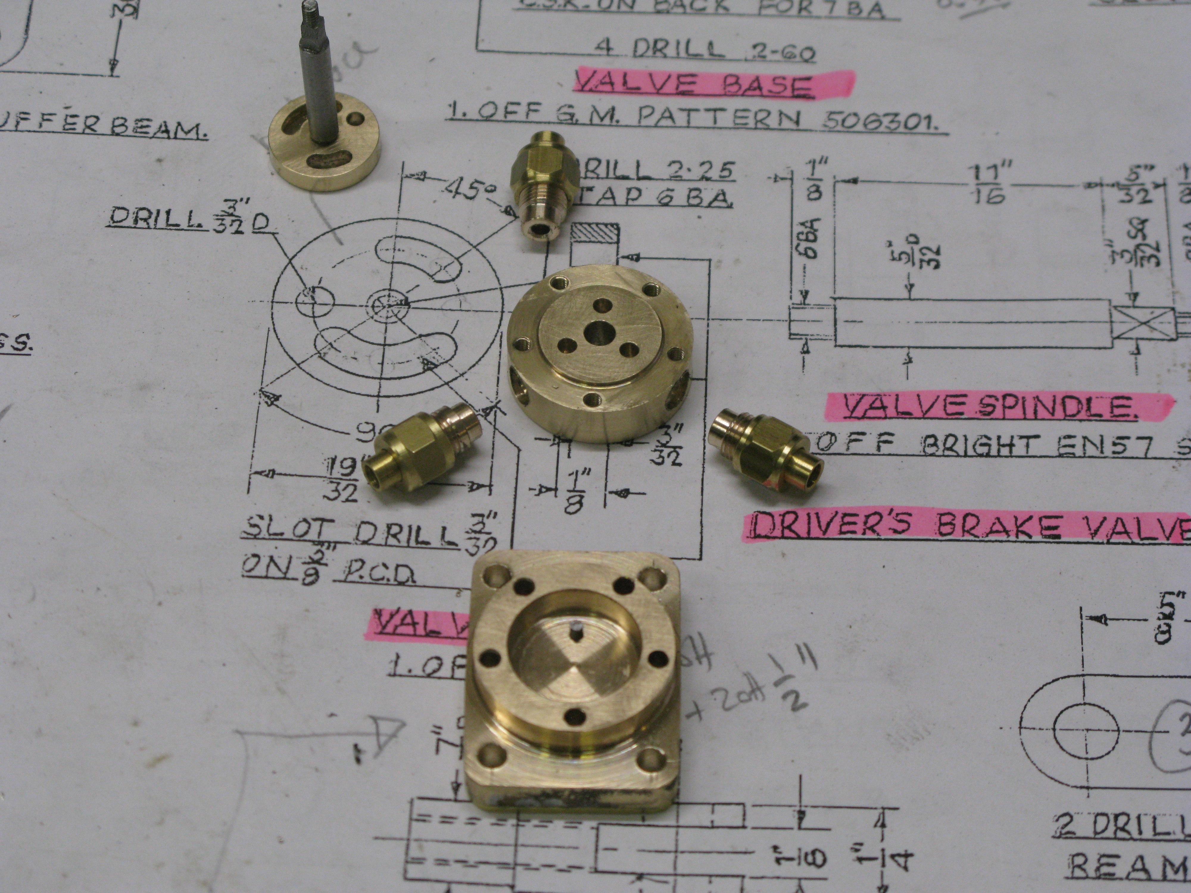
The photo above shows all the parts to be assembled (apart from the handle)
The parts manufacture were really a straight foreward turning exercise and then a bit of drilling. The disc has its two slots milled using a dividing head mounted vertically and using the degree scale rather than the divisions by hole counting. Likewise the hole drilling in the casing parts as they are not equally spaced and the drawing gives degree separation.
The pin the casing body locates in the smaler of the two slots and sets the amount of movement of the handle/disc between the two positions open and closed.
The pipe connections have to be silver soldered in position. The outer body which seals the cavity is screwed onto the base from the rear with c/s 7 BA screws.
To esnure a good seal the disc is lapped to the outer body. It is held against the face by steam pressure alone.
The whole assembly is bolted to the reversing stand with 6 BA set screws.

The assembled and fitted brake valve.
The handle is fitted to the shaft on a 3/32″ square and held in place with and 8BA washer and nut.
Boiler blow down
I have included this item here soley because the blowdown connection is inside the cab and it requires a special adapter to enable a blowdown valve to function.
The problem stems on the left hand side blowdown connection which is very close to the reversing stand. The position of the reversing stand is governed by its fixing bolts to the cab floor and the position of the outside frame which the fixing bolts have to clear. It might just be possible to fit a coventional blowdown valve so it fits between the reversing stand main frame and the reversing lever upstand but it then leaves the problem of what to do with the blowdown exit.

Rather than follow this possible route I decided to make a dedicated self designed solution. This consistes of a banjo coupling that fits to the boiler blowdown bush. The banjo coupling has a 3/16″ exit pipe that is routed to the outside of the outer frame and then bent at right angles to the rear to fit about 1/2″ below the floor. To this pipe is connected a self designed valve with its exit pointing downwards. The valve stem points away from the frame and is operated by a square key and is accessible just below the cab floor.

The other blowdown connection on the other side will have the same solution although it does not have the restrictive matter in the way.

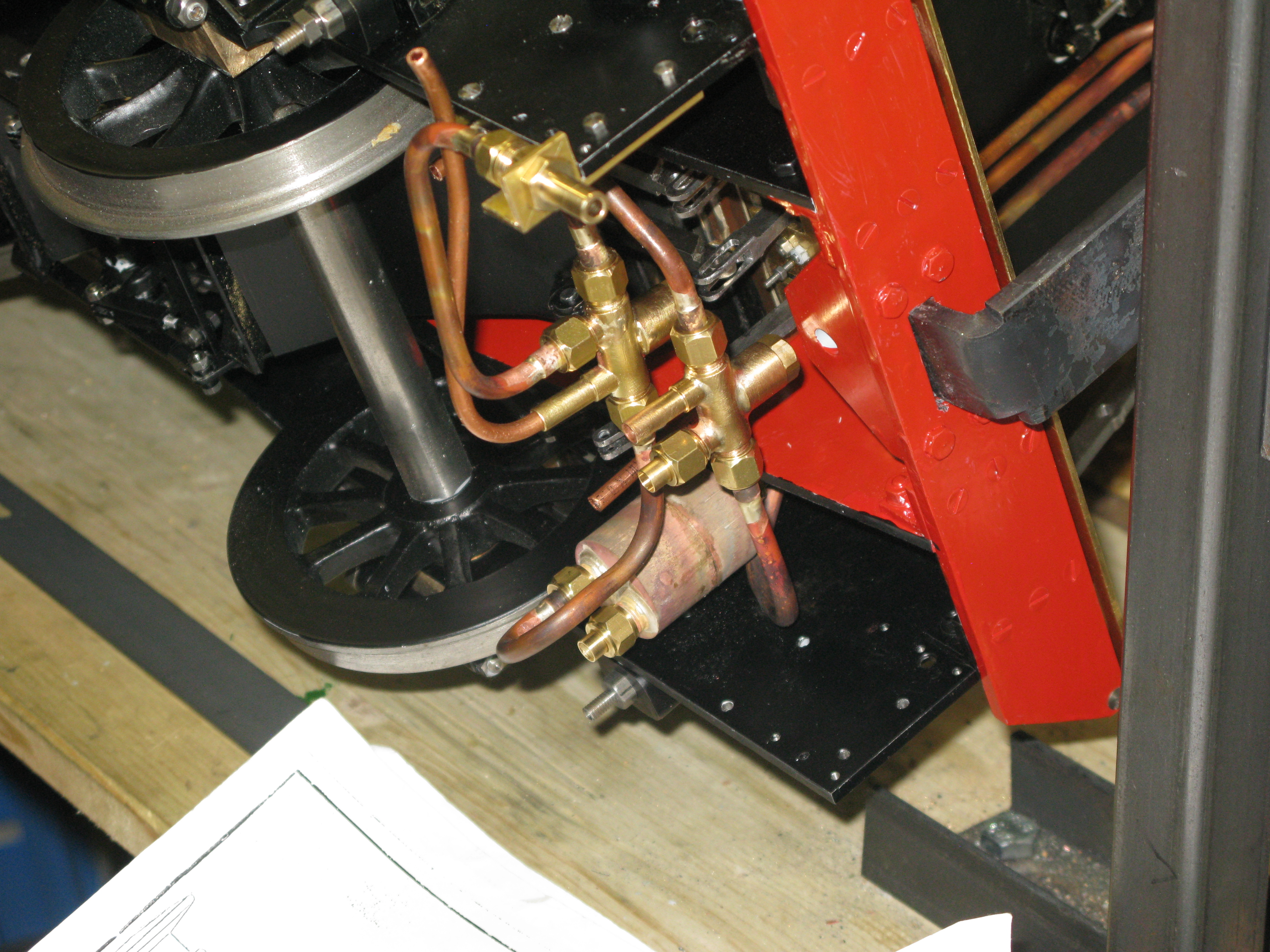
The blowdown valve fitted.
Fire door
The fire door gave me a bit of a problem for two reasons. Firstly the bushes silver soldered to the backhead that take the hinge pin were not vertically aligned which meant making some specially designed hinge pin holders to correct the offset, and secondly the door as designed did not allow for any backhead cladding so was not “thick” enough.
The door was modified to have a 1/8″ thick plate behind an 18 g plate. The 1/8″ thick plate matched the outside size of the firebox door ring and would but up aginst it. The 18g plate being slightly larger theb butted up to the cladding.
The hinge pin supports were machined from brass with a 5 BA threaded portion to screw into the blind bush tapped holes. The there was a 1/8″ wide 3/8″ dia boss to abut the backhead boss and then a 1/4″ square to take the hole for the hinge pin.
With the hinge pin supports temporarily screwed in place they were marked out with a square from the cab floor to get the position of the vertical hinge pin. They were then drilled 3/32″.
The top and bottom hinge pin supports then had to have the 1/4 ” square portion machined to provide an offset to put right the non vertical bosses and allow the hinges to swing.
The hinges were cut from 1/16″ thick MS flat bar and 1/4″ dia. by 3/32″ wide bosses silversolderd to the ends. Thses were then riveted to the forehole door with three 1/16″ RH steel rivets.

In the photo above the door catch has still to be designed and built.
Having considered a few options for the door catch I decided on a simple friction catch. The catch is simply a bent piece of brass strip having a U turn at one end which is riveted to the door. The U turn rubs against the fixed block on the backhead sufficiently to keep the door closed but not so hard as to prevent a light tug on the loop to open the door. I have this method on my Maid of Kent loco and it has withstood the test of time well.

Finished fire door and catch
Water gauges
There are two water gauges in the cab mounted either side of the regulator rod.
The gauges are drawn without isolating cocks other than for the blow down valve which is part of the lower gauge glass connection to the boiler.
The gauge glasses will have to be custom built as they need to stand away from the backhead to clear the regulator shaft in a similar fashion that the feedwater clacks do. The as drawn dimensions do not give sufficient clearance (in my view) so my gauge glass bodies will be slightly longer. Also the left hand lower gauge glass body hex part may well foul the regulator rod bracket, it seems very close.
The gauge glass that I have is nominally 6mm diameter red lined. As drawn it is 1/4″ so again some minor mods to accomodate the small difference.
Another difference I chose to make was to make the blow down valve captive. I did not like the idea of the non captive valve as designed as an inadvertant opening too far would put a jet of hot steam/water straight into the drivers face.
There are many pieces to the gauge glasses and with two to make that takes a bit of time on the lathe.
The components that screw into the backhead are from bronze and the rest are brass.

With the top and bottom comp[onents silver soldered together they could be screwed into the back head to scheck the length of gauge glass needed. I cut the gauge glass by initially grooving with a triangular needle file and this then tends for the glass to snap more or less cleanly. To get square ends I use a diamond flat file with water lubricant and this removes glass quite well without it splintering at the edges as long as the file is not too coarse. To seal the glass I use an O ring which compresses nicely by screwing down the retaining nut. A lick of high temperature paint after an etch primer to the components and they are ready to be fitted in place.

The fitted gauge glasses
Steam turret
The steam turret block comes as a rough casting so the intial work is to clean it up to get square sides. Once this was done the block could be mounted on the rotary table and the plan shape milled.
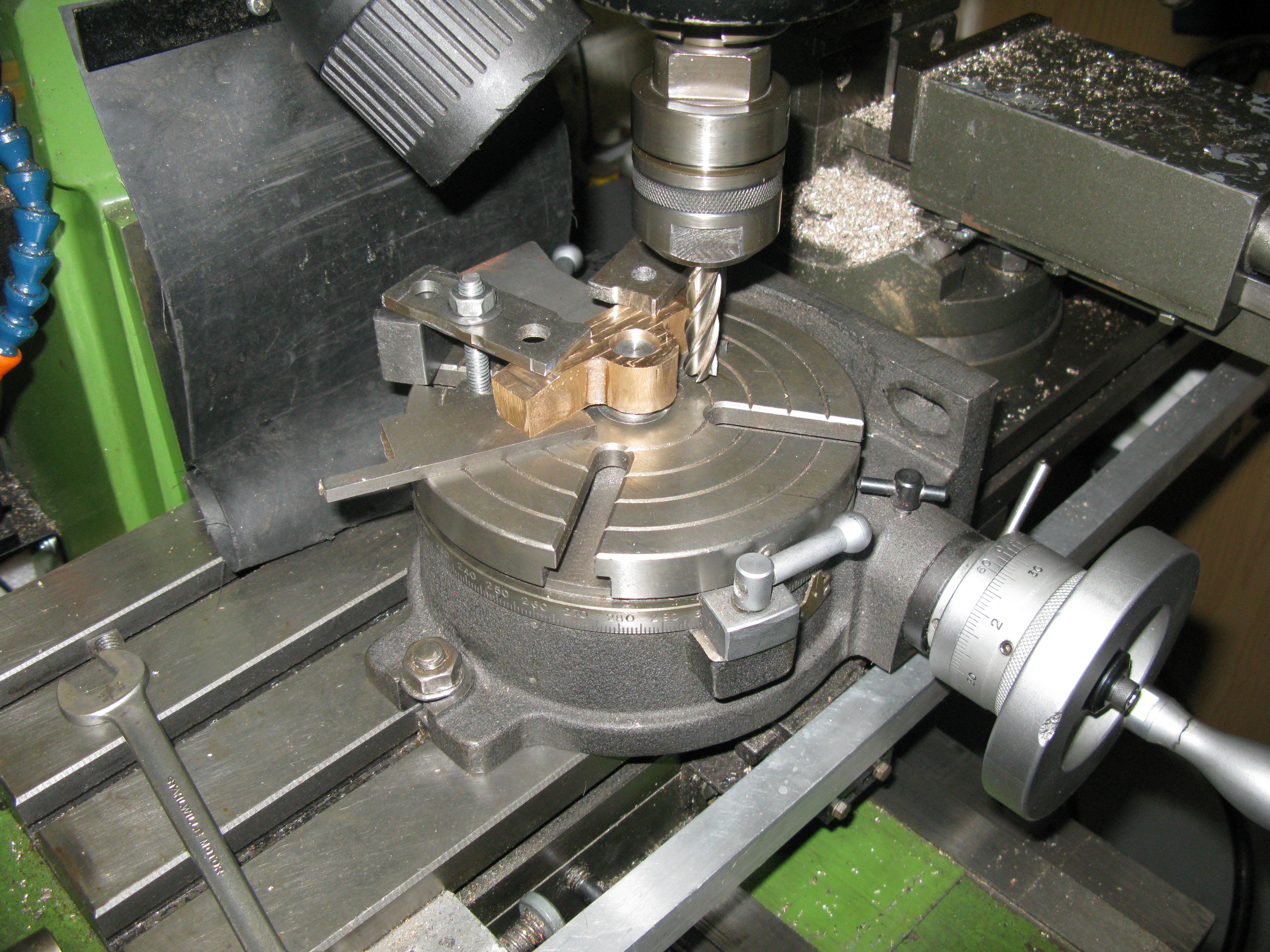
The turret block is a banjo fitting to the boiler hence the shape as shown above.
There a number of angles to be machined on the block most are dimensioned but a couple were left to me to use a bit of trigonometry to work them out. Fortunately I have a set of angle templates that enable me to set any angle between 0 -90 degrees.

Angle templates and parallel and part finished machined block
Machining the angles involved numerous set ups in the mill vice.
Drilling a 6 degree angle using two angle templates
Also drilling the core bore needed the angle templates.
The top and bottom, as seen in the picture, also has to be counter boared parallel with the face to accept a threaded nipple to attach steam feeds to the blower and steam brake respectively.
The remaining holes needed are for the isolating valves for the steam to injectors and the whistle.

Drilling and tapping the 3/8 x 40 holes for isolating valves
The isolating valves for the steam injectors are drawn as having the bodies silver soldered into the block. I was not happy with that arrangement as should there be a leaky valve the whole block would have to come off to service it, which would involve removing the cab. So I chose to have my valve bodies a screw fit.
Also the as drawn valve bodies are too short as the output nipple would foul the backhead cladding. I suspect it would be too close to the backhead without the cladding too. So the body has to be lengthened. However on second thoughts I wondered if the valve could be positioned so the pipe ran away at about 45 degrees. This might be a better solution as it would make the pipework on the backhead neater.

The finished turret block and banjo nut.
The banjo nut on the turret block is drawn with an exit hole at the position of the turret block entry. This was not a satisfactory arrangement in my view as it was not possible to always ensure when the banjo nut was tightened down the holes would align. So I chose to put a grove around the banjo nut so it was not important where the nut finally tightened down and allows for any type/thickness of washer to be used.
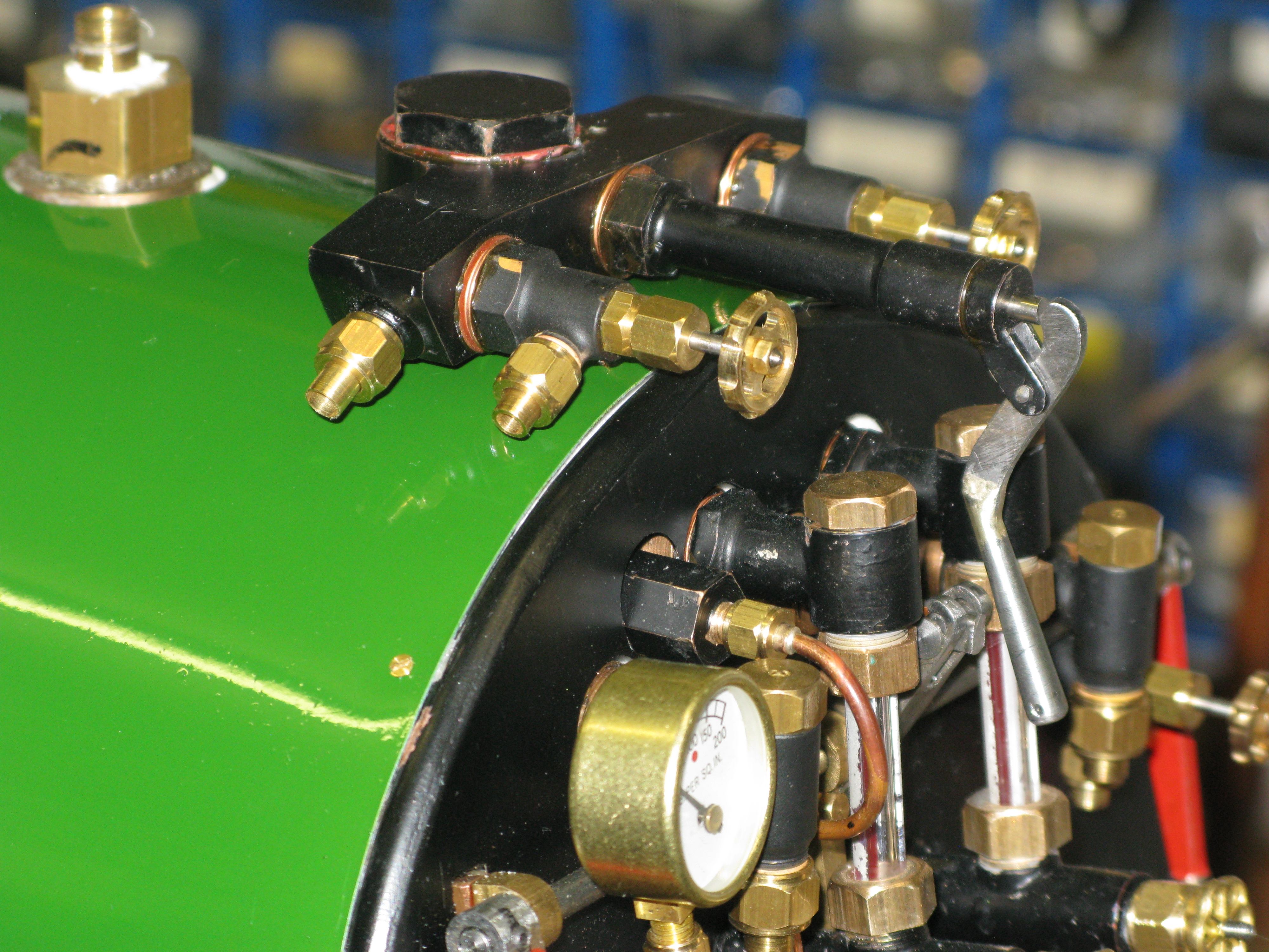
Pressure gauge fitted
The finished turret block has the two injector steam valves fitted and the whistle valve. The injector steam valves are commercil ly bought items.

The fitted turret block
Turret block in place
Whistle valve
The whilstle valve is not as drawn but a bespoke item to a design published in the Model Engineer many moons ago. I have built and used one before and it is definitly a reliable valve, doesn’t stick and operates esily.
I had to modify the design so as to clear the regulator valve rod and give room for the exit pipework which makes the overall length of the valve longer.

I also had to make the handle a pull version rather than a push version as the valve sits up close to the cab roof and there is no room for the handle. This modification also allows me to use a chain pull in the cab.
The basis of the valve is an O ring seal at the steam entry with the valve spindle having an internal spring to keep it closed at low steam pressures. The valve spring is stainless steel 3/16″ in diameter and approx. an inch long. There is also and O ring seal around the valve stem held in place by the handle mechanism when it is screwed into the body.

The handle has a No. 60 hole through its extreme end for the attachment of a pull chain.
Drain cock operating lever
The drain cock operating lever is a typical handle which pivots about a pin mounted on the frame. The pin is such that the lever stands out away from the frame by a 3/8″ distance piece in the form of a nut that screws onto the pin . The operating rod from the lever to the drain cocks is mounted roughly midway up the lever and is on a pin which also makes the rod stand out from the lever. All this to ensure the rod clears the cladding as it exits the cab.
The lever is made from 1/8″ mild steel flat and I chose to cut its shape using my little CNC mill.

Lever as cut on CNC mill
Lever fitted to its fixing pin.
Grate operating levers.
The rocking grate operating levers are small stub levers mounted to the cab floor. The full size have lomg opearting levers that fit over the stub levers and give a good purchase for the fireman when rocking the grate . When not in use they are removed and leave the cab free of obstruction. Mine are similarly designed. The rocking lever itself is a clevis design to fit over the rocking grate shafts and they rotate about an axle just above the cab floor.

Trial fit of the rocking lever and axle support.
The slot in the clevis is necessary as the arc circumscribed by the rocking grate rods when rocked is not the same as the radius arc of the lever.

Trial fit of the assembly on the cab floor to ensure the grate rocks to full travel.
The trial fit showed that I had no relief machined onto the rocking grate rods where the clevis joins. So a relief had to be ground and filed in situe as the rods cannot be dismantalled. Took a while but had to be done.
Final fit of the supporting barckets for the axles.

Underside view of fitted rocking levers.
Onto the next job.
Ashpan doors (damper) operating lever
The operating lever for the ashpan doors is a simple lever moving up and down and being able to rest at the closed, open and halfway positions. However the actual production of the lever and its assembly was not so simple. There is no drawing for these parts so it was back to the drawing board to come up with a suitable design. My practice for such events is to use CAD to set out the main critical dimenmsions, print it out full size and then just doodle ontop the concept in pencil which I can rub out and modify to my hearts content.
The stand into which the lever must slot to allow the lever to be rested in the three positions clearly has to be high enough to accomodate the full travel of the lever. This meant it might be a bit flimsy so I decided the stand would be three sided to provide a stiff support. The edges would contain slotted holes at a slight angle to ensure the lever would not drop out with vibration while the loco was running.
The eventual stand turned out to look like the photo below in its partial completed form.
Partially complete stand and my doodles for the design.
The stand first had the holes drilled then the sides were milled away and finally the 1/8″ slot was machined with a slitting saw.
The lever needed to have a slight offset at the bottom to allow it to clear the backhead and the handle at its top needed to clear the stand and have a handle to grab to lift and lower it.
When assembled onto the cab floor the stand sits just an 1/8″ c;ear of the back head and adjacent to the rocking grate levers.

Fitted lever and stand – just needing a tidy up.
The slot for the lever in the cab floor has to extend in front of the stand to allow the lever to clear the resting slots when moved.
All fits and works thankfully.
Pipework
Time now to do the backhead pipework. There are three aspects to this; the blower, the injectors and the steam brake.
There are drawings showing the pipework which is helpful, however there are a couple of things I am chosing to change. The first is the overflow from the injectors. As drawn the overflow is taken to the opposite side of the loco from the water and steam feed to them. Personally I would find it confusing and perhaps annoying to have to look to the opposite side from the side I am operating. So my overflow will exit the same side as I am operating. The second is the arrangement of the feed water flow from the second injector and hand pump. There are only two clacks on the backhead so one has to be shared between the hand pump in the tender and an injector. The arrangement for doing this is to put a non return valve on the injector output and T the feed water to the boiler from this and the hand pump, relying on the nonreturn valve in the hand pump when the injector is working. I was unhappy with relying on the hand pump nonreturn valve and also it is distant from the injector output so I have chosen to make a double non return valve to fit just after the injector so the hand pump also connects to it. Its a home brew design consisting of two non return valve chambers in a common body and exiting into a single outlet. As alway time will tell if its successful.

Double non return valve and my sketch design

There is a third item, the connection the the hand pump in the tender is drawn as hanging in free air in the middle of the dragbox width and relying on the stiffeness of the pipework attaching to the intermediate check valve described above. I doubt that arrangement would last very long so I will be moving the attachment to sit alongside the right hand water feed to the injector and make the water feed bracket more substantial so the arrangement will readily accept the spanner forces in tighteneing and undoing the connection.
One problem I came up against early on was the steam feed to the injectors. It is 3/16″ pipe. However the steam valves on the turret only have a 5/32″ copper pipe connection so I had to make a small pipe adapter to step up the pipe size immediately after the valve outlet. I hope there is not too much throttling taking place and there is sufficient steam to operate the injectors.
The blower pipe (5/32″) from valve to blower connection on the backhead is only a short run but it has a couple of awkward angles to negotiate as it leaves the turret block vlave and then slopes down over the cladding and then loops over the backhead and then down and up into the blower pipe connection. As with most pipework I find the number of times the pipes come off and on is quite large in order for the fit to be aquired.

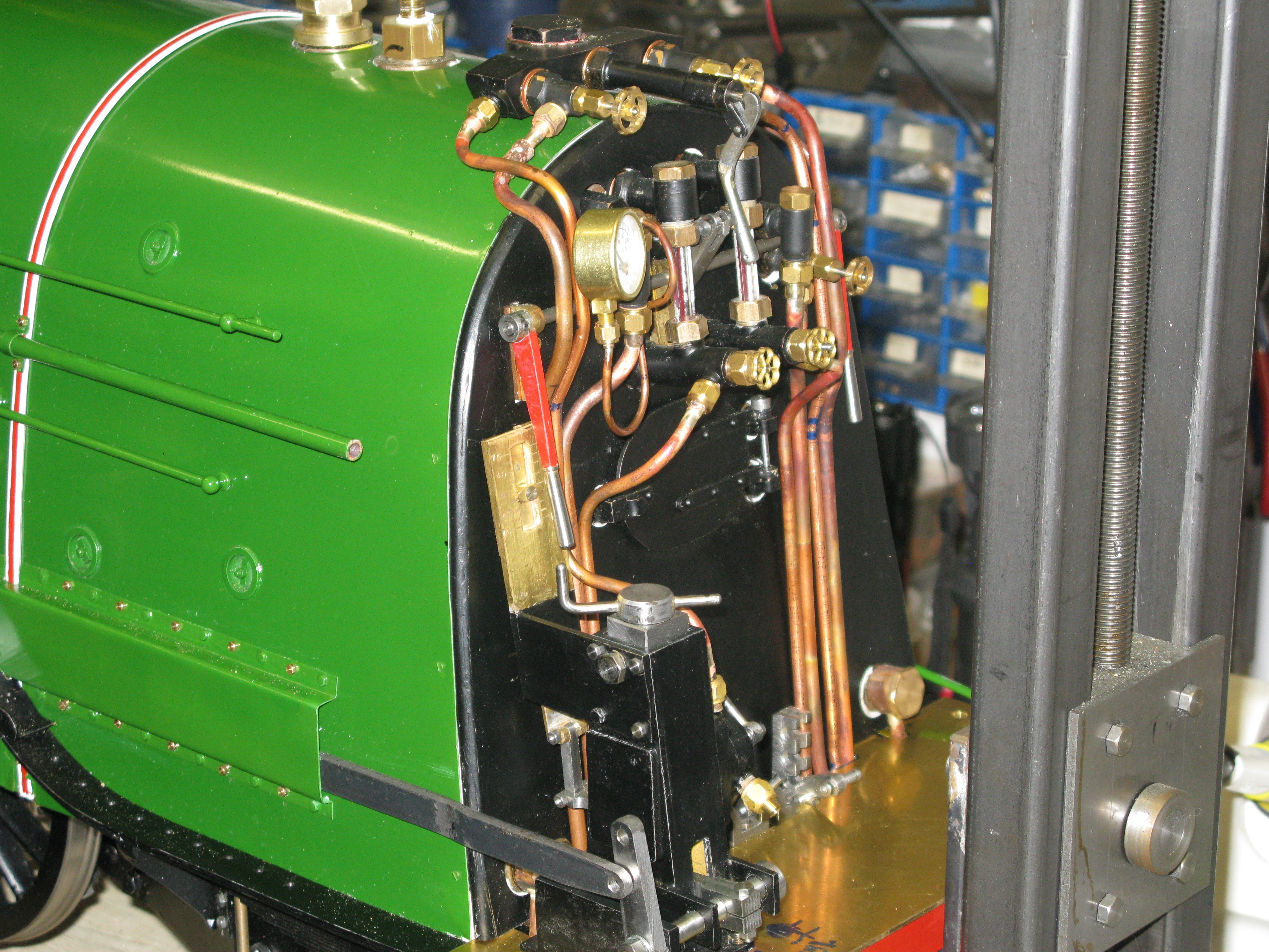
Backhead pipework in progress
The pipework in progress is seen above. There remains to be done the steam brake and an injector overflow and the hand pump feed water and the whistle …….. nearly forgot that.
The injector pipework can be seen above with the double return valve in position. The right hand injector overflow pipe has yet to be fitted and the feed water pipework from the hand pump and feed water to the nearest injector
The whistle will be fitted alongside the injectors so the underfloor area will be quite congested!

All except the steam brake pipework is now done underneath the floor.
I completed the whistle pipework and the remaining underfloor pipework as can be seen above. However, I failed to appreciate that the hand pump water connection to the non return valve was too low and when I turned the loco back to normal it was at rail height. So that pipe has now been turned 45 degrees at the tender connection and a corresponding bend put in at the non return valve and all is now well.
All pipework to the turret block now done with the addittion of the steam brake pipe.
The steam pipe to the brake valve has now been put on and that just leaves the pipe to the cylinder to be done and the short length of exhaust to under the floor. I have cut a hole in the cab floor central to the steam valve and the pipes will be bent to go through it. As fitting the pipe to the cylinder will be almost impossible due to its length and path I will put a through joiner in the pipe at a convenient position that allows for the pipe that connects to the valve to be assembled more easily.

Pipe run from brake valve to cylinder.
The pipe joiner in the above phot is just about visible behind and above the cartazzi axle.

The valve end of the pipe to the brake cylinder and the axhaust which just goes below the cab floor.
