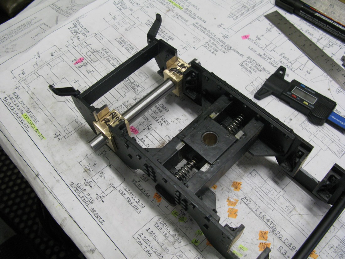
The front bogie is an assembly of frames and stretchers with conventional hornblocks and axle boxes. The assembly swivels around a central king pin on a block that is able to slide side to side under the control of compression springs.
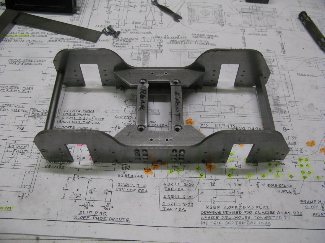
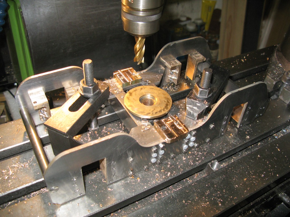
The king pin is mounted on a stretcher in the main frames and this is the first item to be made. It is a casting that needs machining to give flat surfaces top and bottom and a stepped side to fit between the frames.
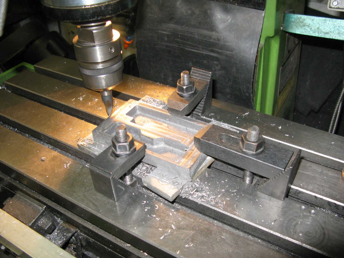
The casting is common to a number of locos and in the picture above there is an obvious relief in the central web that is not used on the A1.

The cut out in the casting top right is for the cylinder drain cock lever clearance. The central bore is 1/2″ reamed.
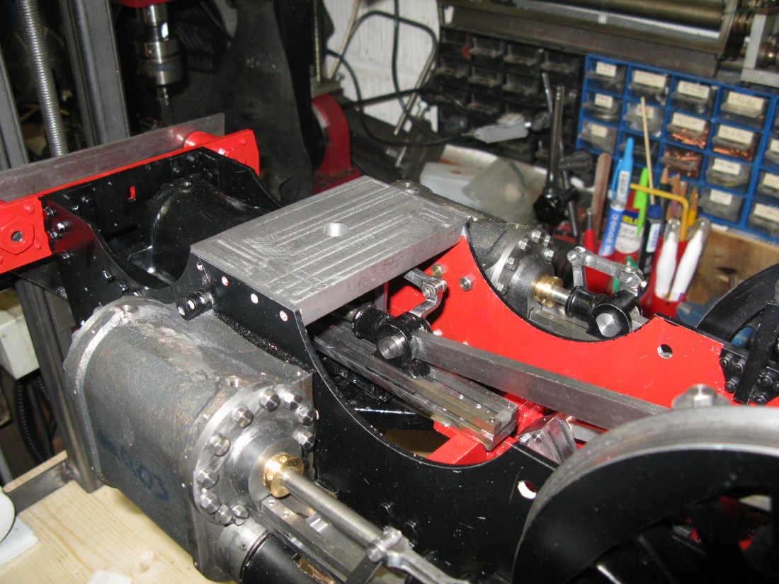
A trial fit in the frames proved a very good fit once I had removed the paint! The stretcher is held in place b the four 4 BA bolts through the frames which scre into tapped holes. Just a lick of paint and that can be fixed in place.
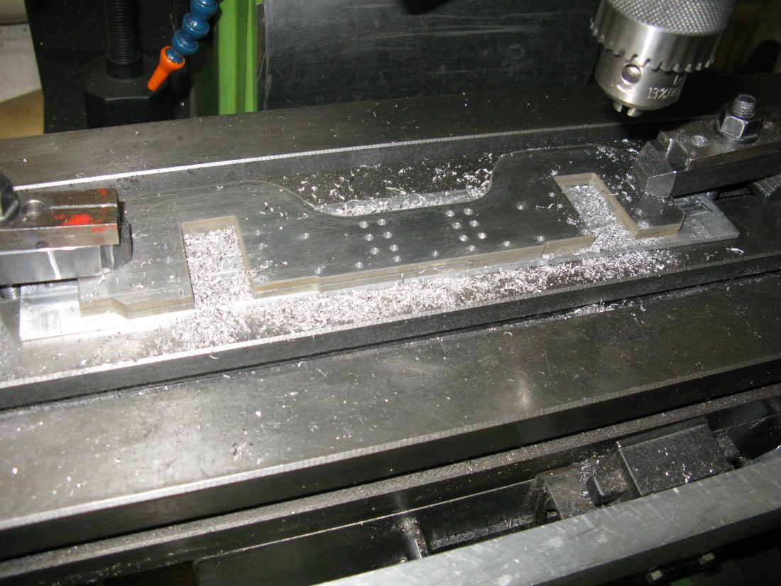
The frames from 1/8″ steel plate were water cut when I had the main frames done …. that’s over two years ago now. The holes are drilled using X and Y cordinates on the mill referenced from the axle box centre line at one end.
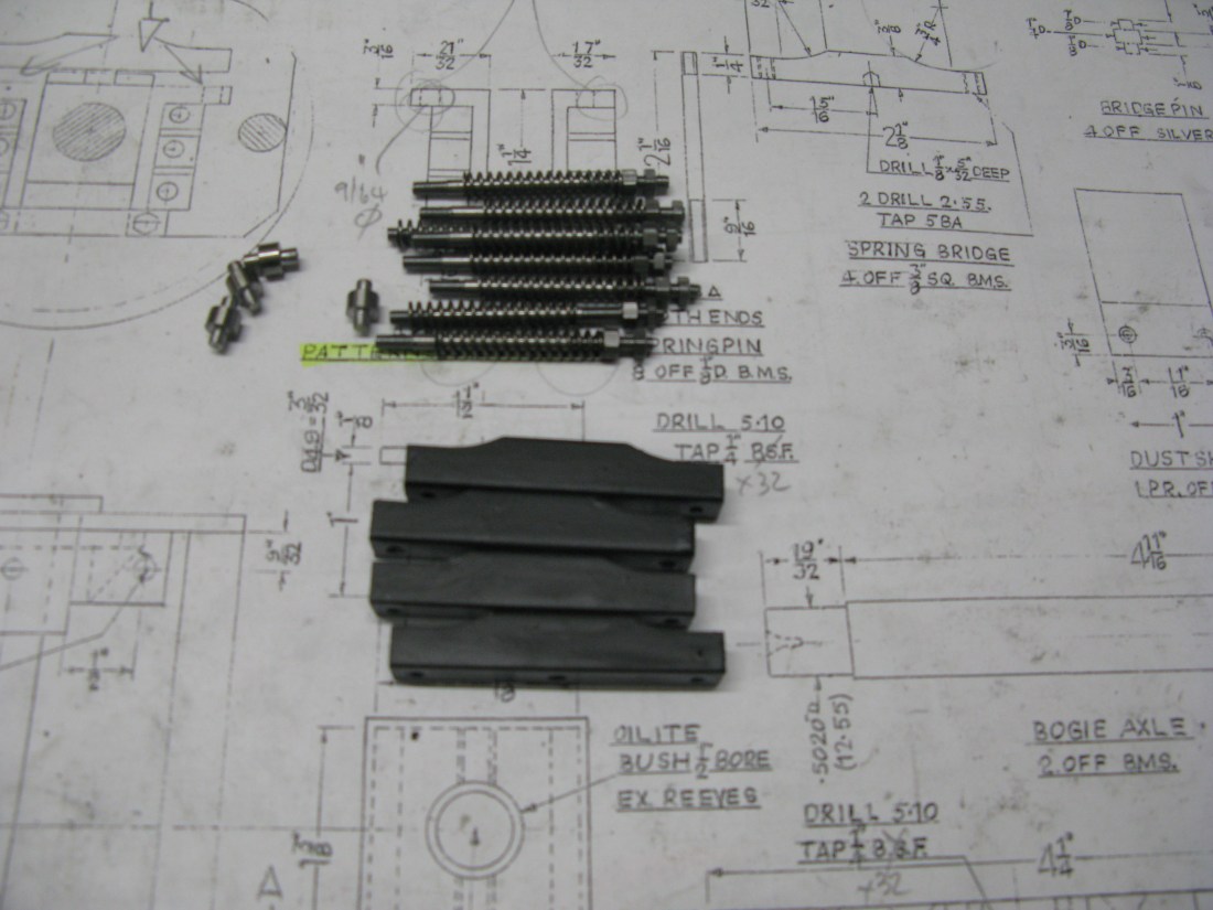
The kingpin is a straight forward turning exercise but being sure to make the fit into the stretcher a good sliding fit and that when the top nut is tightened the pin is square all round to the stretcher.
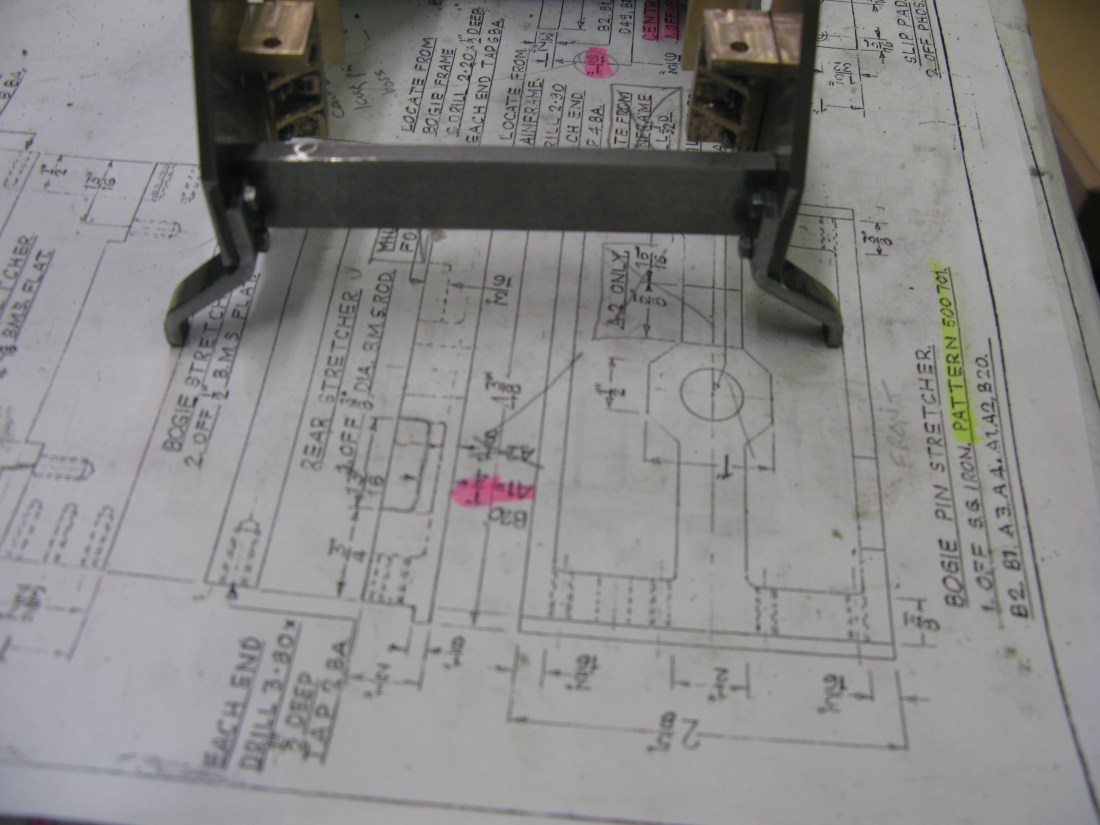
The bogie stretchers consist of four items. The front stretcher is a simple 3/4″ x 3/16″ bar drilled and tapped for two 6 BA c/s screws in each end. The rear stretcher is a 3/8″ rod drilled and tapped for a 2 BA c/s screw at each end. The middle two stetchers are 1″x 1/2″ having six 6BA c/s screws in each end. They act as the carrier for the centre block to slide from side to side. They also have a recess at the ends on the top for the frame strengthening angle plate.
four stretchers trial fitted
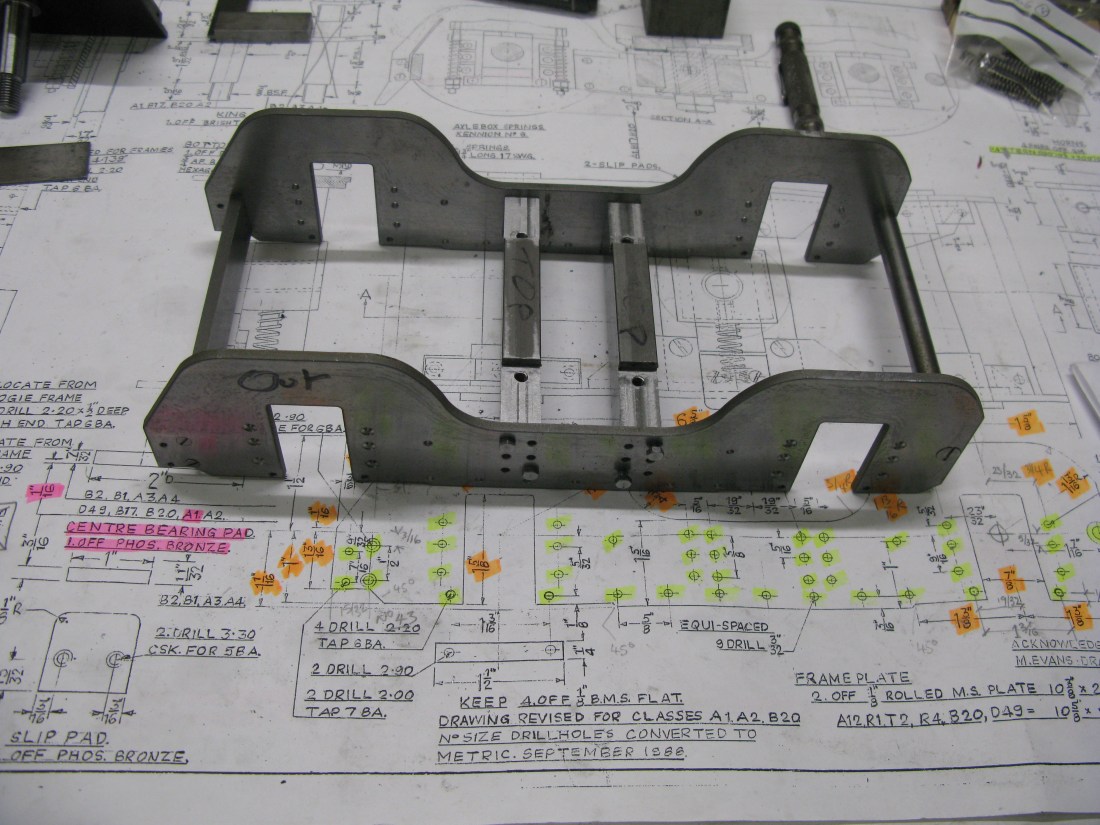
As I progress with bits and pieces for the bogie I am finding the drawing needs care in examination as it covers no fewer that 13 loco’s! So making sure I am doing the right bits for the A1 is taking some time. It does’nt help when it seems that there are contradicting measurements on odd items and missing holes on others.
Frame strengtheners trial fitted
The frame strengtheners are made from 4mm MS angle 30 mm x 30mm. They are bolted to the frames along the bottom and a single bolt at the top left and top right corner. They fit over the stretchers so they have two rectangular cut outs to accomodate them There are two 2BA c/s screws holding the top down. The bolt holes were all jig drilled from the frame for 7 BA set screws.
The central bearing block that fits between the stretchers is machined from 1 1/2″ square MS. It is machined on the sides to give a 1″ wide slot so that it slides between the strechers. The drawing calls fo an oilite bust to be fitted but I chose to fit a PB brush press fitted into the block.
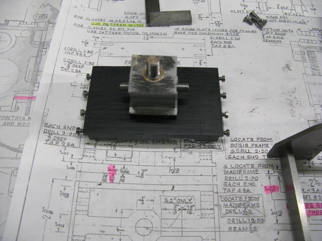
Checking the bearing fit on the kingpin
The block has a 1/4″ dia pin fitted to each side to locate the centering spring. The pin is simpley screwed into the block with a 1/4″ x 32 ME thread ( although the drawing calls for 1/4″ BSF). I chose to use the ME thread as there is a similar pin in the frame strengthening bar and I thought a 1/4″ BSF was a little coarse for a 4mm thick plate.
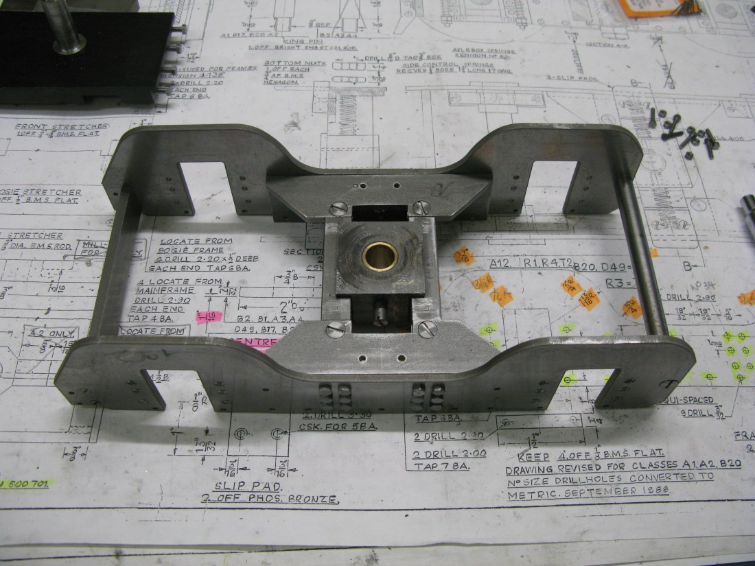
Checking the bearing block slides up and down freely in the frames.
Eventually when I get around to painting the bogie the bearing surface will be left bare.
The two tapped holes that can be seen on the top of the frame strengthening plate are there to fit a PB or brass slider. There is also a PB circular pad that fits on top of the bearing block and together they form the bearing surface for the bogie.
However, there is a problem. The drawing states the A1 circular pad is 1/16″ thick, but it sits over the 1/8″ boss of the king pin which the fixing nut draws onto to hold it in position. So it would not be a bearing pad at that thickness. The options were to recess the stretcher to accept the boss or to make the pad slightly thicker. Having measured the distance from the tread of the main wheels to the centre of the bogie horns I reckoned that the second option was the one to take. This has a nock-on affect to the thickness of the side slider pads. Fortunately it is just a question of measuring the gap and making them accordingly.
The horn blocks are a casting that has to be split into two halves and then rough machined to get square surfaces and generally cleaned up as can be seen in the above photo.
However there is a drawing anomoly as the horn blocks are drawn as seperate items with one having the top as shown in the photo above but its partner has a shorter top finishing level with the side, but all other views of the bogie have the two horn block identical with the long top. So that is how mine are going to be.
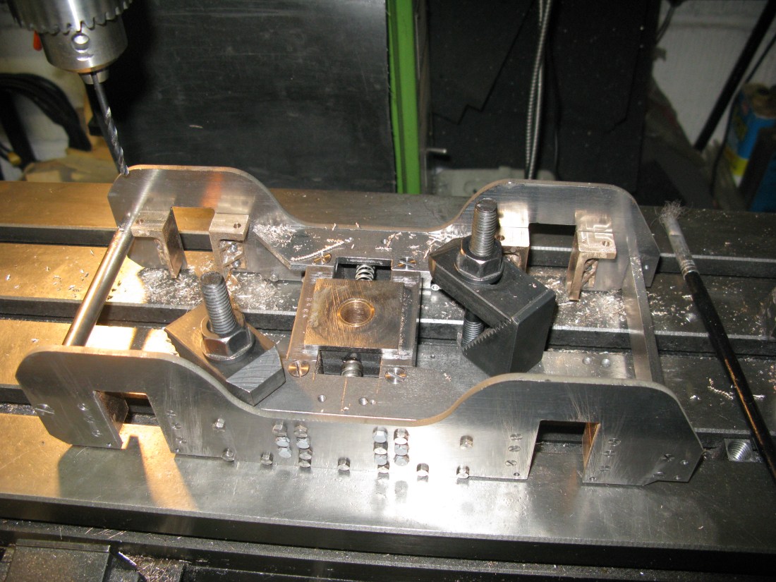
The keeps were fitted, they are a single 1/8″ x 1/4″ bar that bolt to the two tapped holes that can be seen below the horn block. The horn block is then clamped to the frame so it sits on the keep and over laps the frame cut out to allow machining to size. It is then jig drilled for the fixing screws.
Jig drilling the horn block on the frame.
The fixings are not specified. I used 7 BA c/s screws and nuts but I suspect 3/32 rivets may be used and hammered into the c/s specified hole in the frame.
The horn block webs should be evenly spaced so the fixing holes sit in the middle between the webs, however the web at the top of the horn block is closer to the top on one half of the casting which means the fixing hole is nearer to it and a nut cannot fit to the bottom of the casting. To overcome this I just filed the nut down to just above thread depth on one flat and that gave enough clearance to fit flush on the bottom.
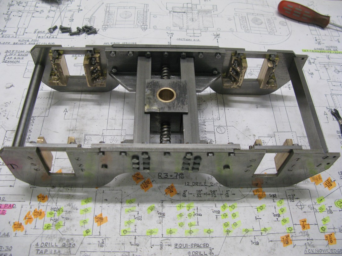
All hormblocks fitted……. just have to shorten the fixing screws
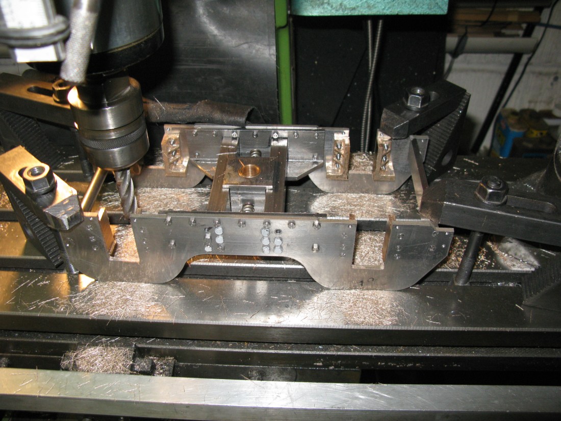
With the horn blocks fitted they can be machined to be 7/8″ wide. This was done on the mill by mounting the bogie on the table square and milling across the bogie.
The photo above also shows the centering springs have been fitted. These are a commercial item. The spring was bought as a long length and cut to the required length to fit so in the central position there was no force exerted by the springs on the block.
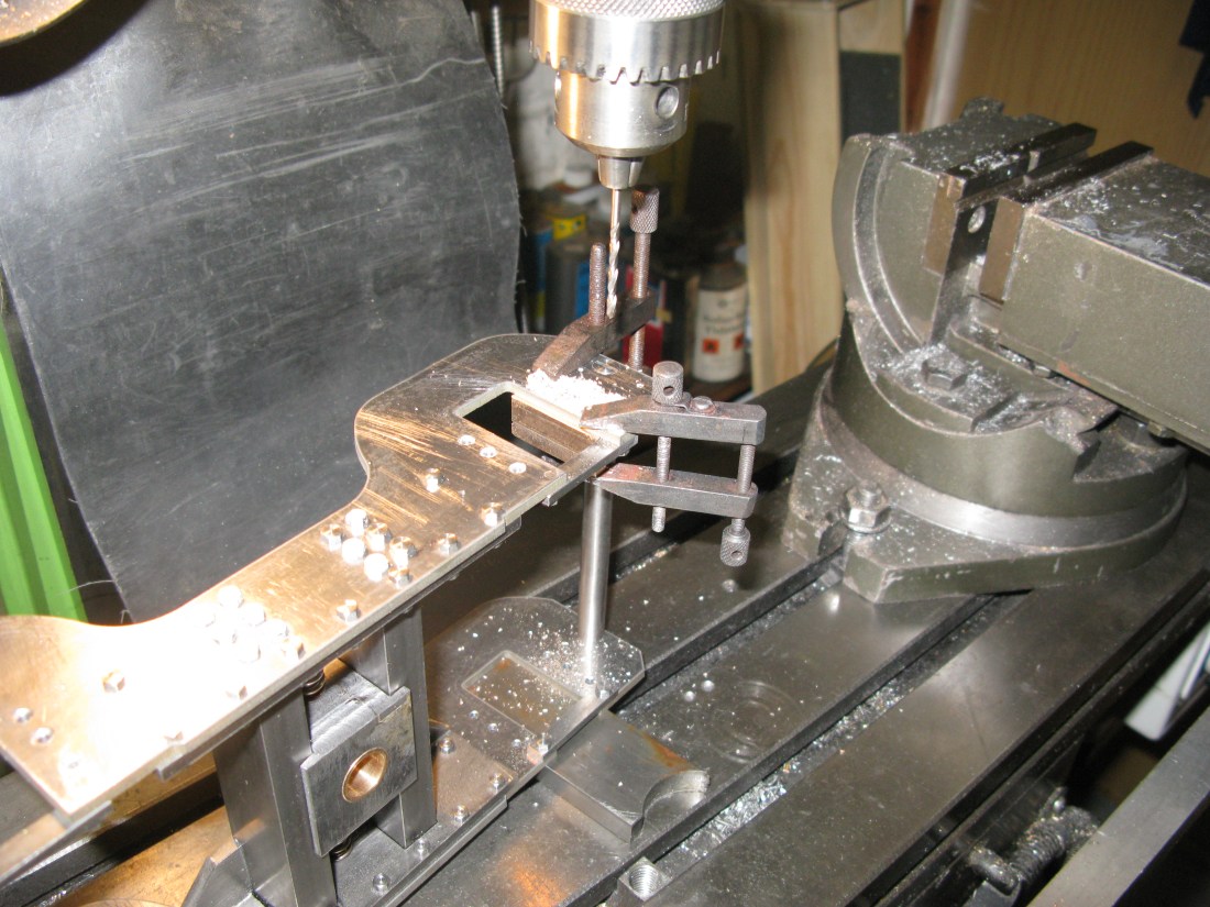
The last drilling operation on the horn blocks is to drill the tops to take the spring hanger.
drilling for the spring hangers
Earlier on I remarked about the bearing plate thickness etc, well the slipper plates proved relatively easy to do. A piece of 1″ square PB was cut to the approximate thickness (oversize) drilled and countersunk quite deeply for the 5 BA fixing screws. The two pieces were then bolted to the bogie and using the round bearing plate as a gauge the bogies slipper plates were milled to the correct thickness.
centre bearing plate being used as a gauge to get the correct depth for slipper plates.
The rail guards that fit on the front of the bogie are not that straight forward to make. There are formed from 1/8″ thick MS flat bar an 1″ wide and have an offset as well as being tapered.
Trying to bend bar of these dimensions cold does not make for a decent bend over a short length. Trying it hot was no better because of handling difficulties from the time it is heated to getting it in the vice accurately so I resorted to bending cold with the use of vice mounted bending blocs. Thses are magnetic blocks with one a V and the other the blade. The problem with this method is that the sharp angle tends to cause a fracture on the outside of the bend. However I decided that this was OK as the fracture could be “filled” with silver solder.
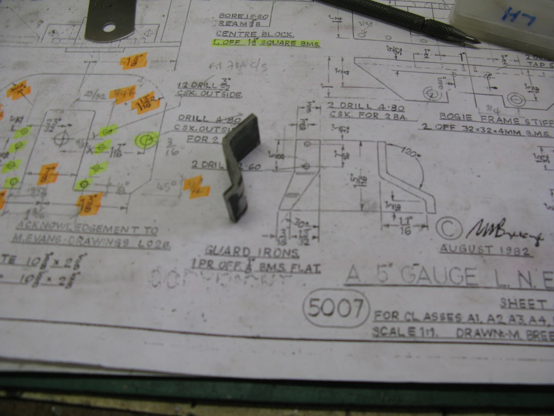
Bends put in the bar
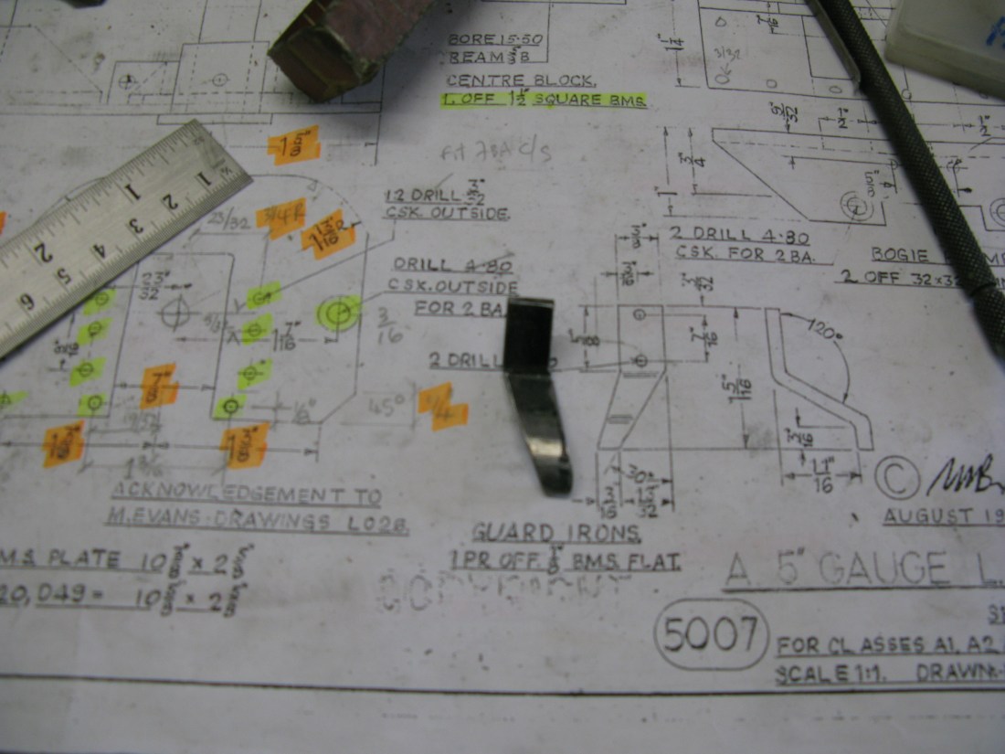
The forward taper cut
Once bent and cut to shape the guards were jig drilled from the bogie frame for 7 BA set screew fixings.
The fitted guards
With the slipper plates and rail guards done the bogie frame can now be painted.
The axles were turned next. A straight forward turning task to produce a 9/16″ diameter shaft with 1/2″ diameter ends (+0.0015″) for press fitting the wheels onto making sure the gap between the wheel diameters was exactly 4 11/16″.
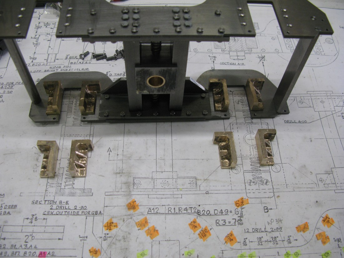
The bearing blocks are from a gun metal cast stick. This was cast at a size barely able to get the four blocks cut from it and also for each block to be machined to the as drawn dimensions. However with a couple slightly undersize overall the actual important dimension that fits the horn block was all OK
Machining one horn block face
The horn blocks were machined in the mill vice. The process was to mill one face that fits into the horn block and then turn it over and put on parallels to machine the second face. With two parallel faces done the block can now be moved in the vice and using a square and/or parallels set up to do each of the remaining four faces.

All four bearing blocks machined and fitted
Each bearing block was individually fitted to a horn block by hand as they were all left a few thou oversize and the machining of the hornblocks were also a few thou undersize in width. Using a file it did not take much effort to file away both to get a good sliding fit. Hence the identifying marks on the bearing blocks.
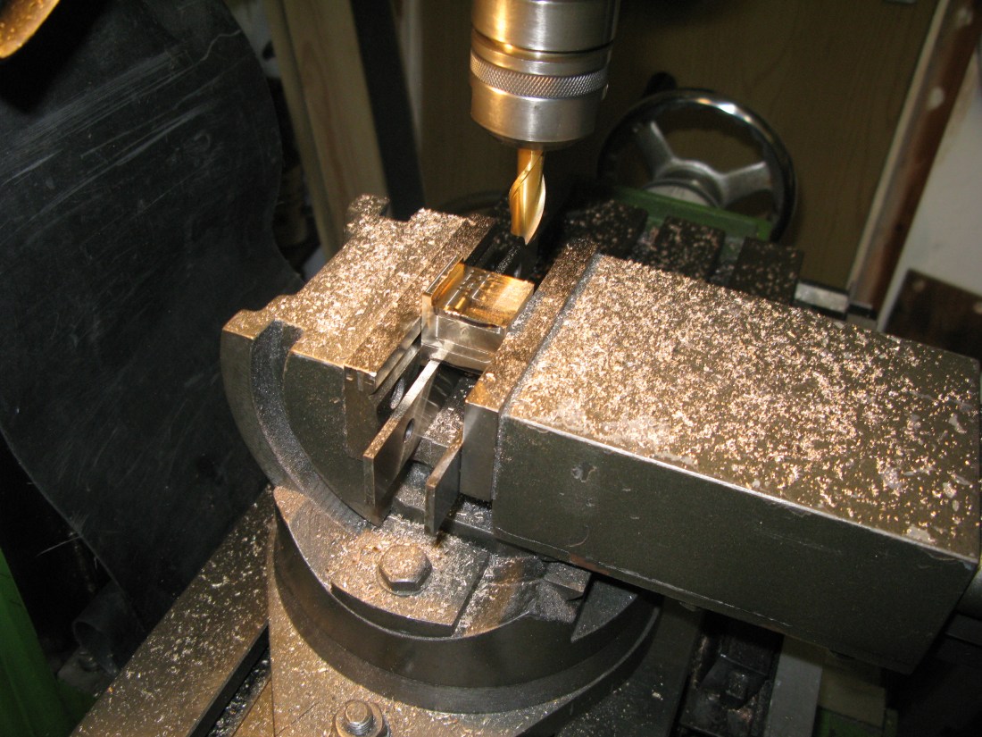
The blocks were bored on the lathe for the axle using a four jaw chuck. To get the block correctly centered in the chuck I used a square to set the chuck with one side vertical to the lathe bed and then a DTI against the vertical side, turn the chuck 180 degrees and check the DTI is the same figure with the top slide at the same position adjusting the jaws as necessary.
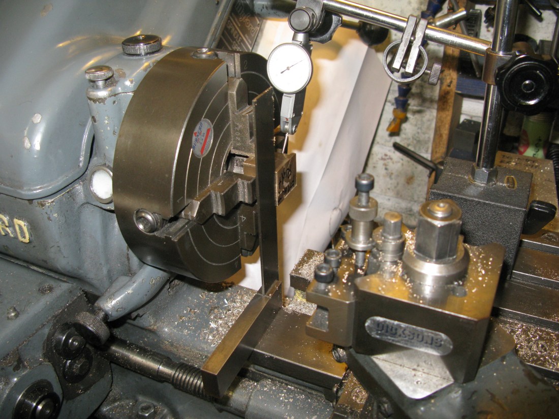
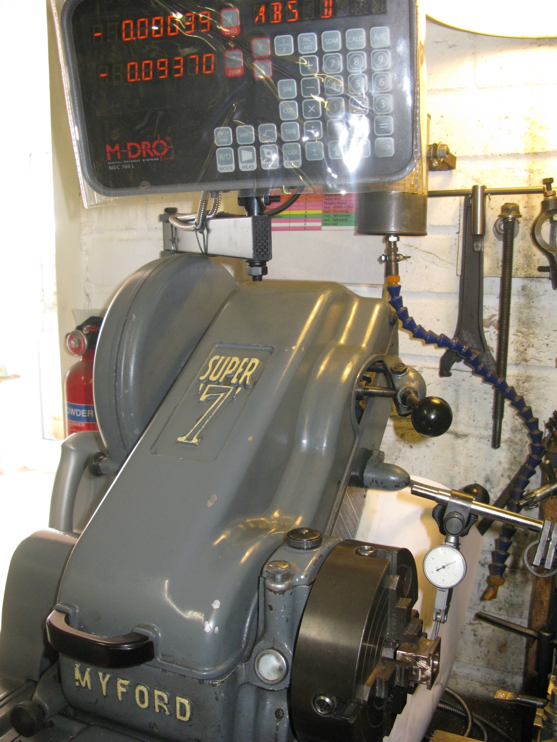
Using the DRO (top reading) to check top slide position
As I have a DRO on the lathe I am not reliant on reading the topslide handle divisions to check the top slide position.
However I have to admit to having done this on the first block and bored it to size only to find when I took it out of the chuck it was off centre! I can only assume that I was on another planet when I set it up! The offending block was bored out and sleeved to bring it back to size. No other mistakes were made on the other three.
The first of two axles fitted
The axle springing is by two coil springs hung from a bridge over the horn blocks. The axle block connects to the bridge by a small spacer that fits into the axle block and bridge. The bridges are machined from 3/8″ square MS and have a curved upper face of 3/4″ dia. at the ends.

Machining the curved upper face at one end
I used the mill and boring head to cut the curved surface and then milled the end flat to meet the curvature.
A set of bridges and spring hangers
Onto the wheels. These are castings as usual and the method I adopted had three stages. The first was to machine the front face flat and its boss in the four jaw chuck getting the inside edge of the rim to run as true as possible as that is the edge that tends to show up most if off centre.
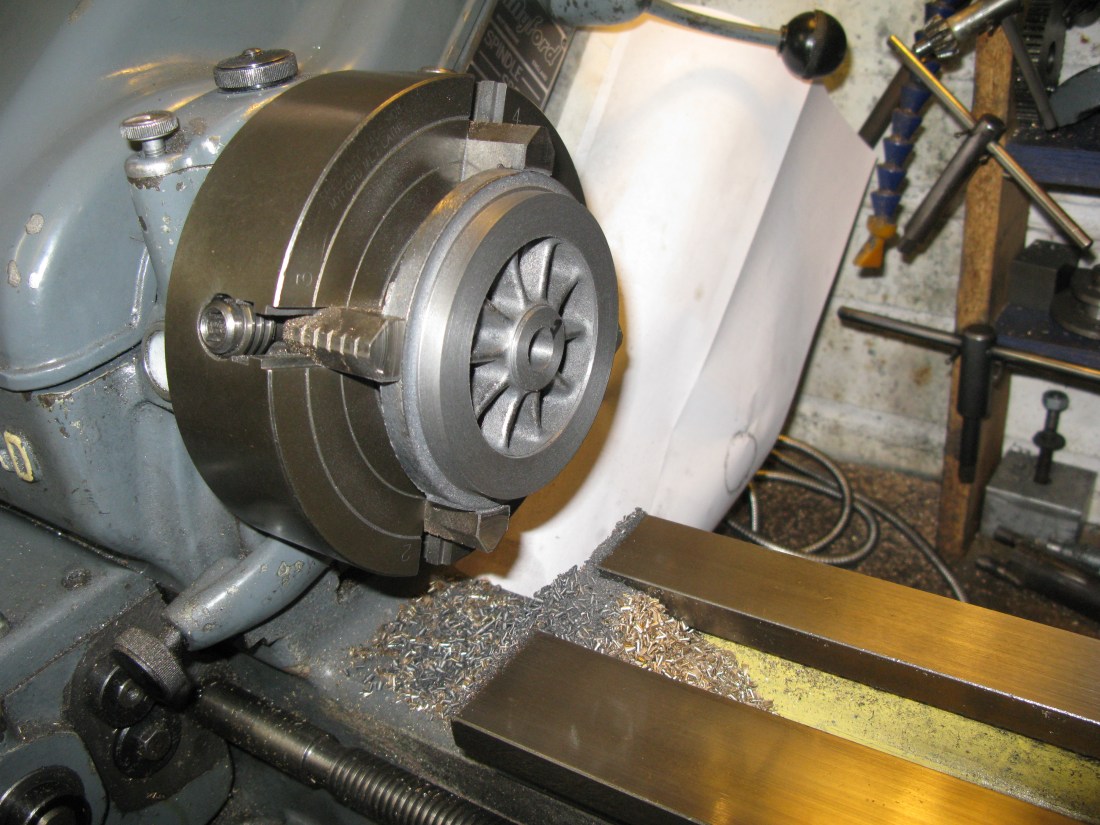
The bore to fit the axle was also done. I intended to Loctite the wheels on the axle so the bore was a good slide fit rather than a press fit.
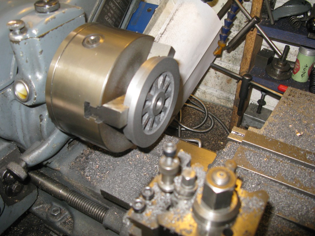
The second stage was to use the three jaw chuck to machine the rear side flat and also to width.
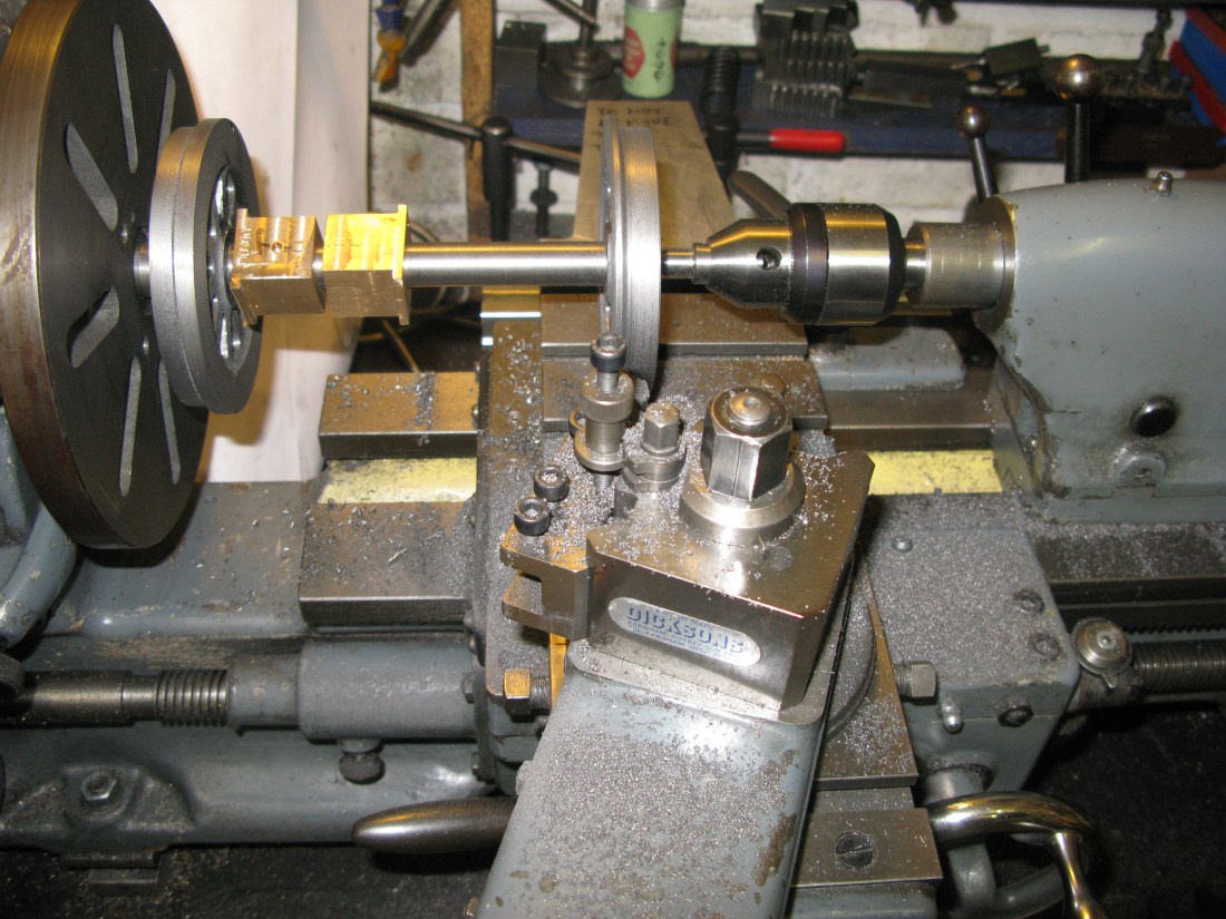
The third stage occurs with the wheel on the axle to machine the profile. The wheels were fitted to the axleswith loctite and left for 48 hours to ensure it had set to the maximum cure.
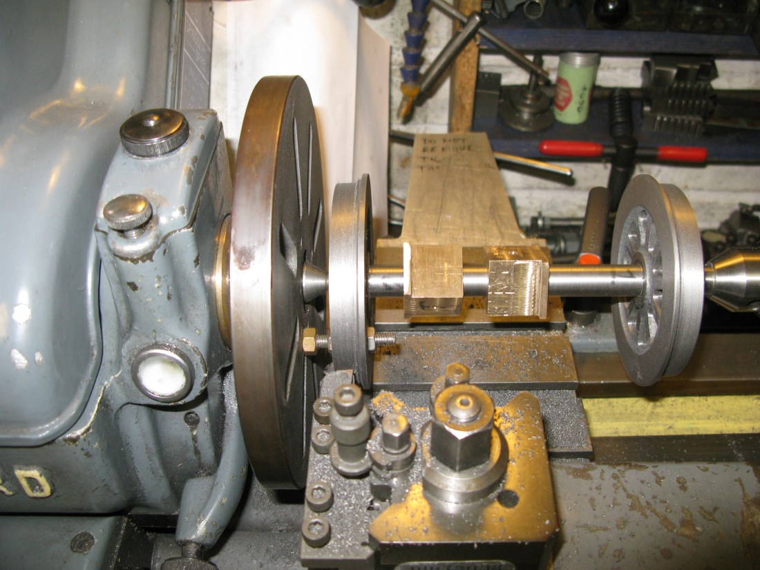
Both wheels were machined with the same set up on the lathe. The face plate had a threaded hole into which was put a 6mm threaded bar to act as a driver. The wheels and axle were set between centres and a nut on both sides of the spoke on the driver to hold the wheel firm to avoid chatter. It was not done up tight just a light nip otherwise there was a tendency to throw the axle out of alighnment and produce a slight wobble even though held by the rear centre.

The outside wheel was machined first. the tread diameter was turned to just over 3 3/8″ and a witness cut then taken at 3 3/8″ on the outer edge. The 2 degree taper was then machined to the aproximate point of the flange radius the final cut being at the witness cut diameter.
This was followed by machining the 20 degree flange so that at the top of the flange it left a 3/32″ width which would be subsequently radiused. The inner flange radius was put in with a 3/16″ round file.
By changing the tool the inside wheel could follow the same process.
Machining the 2 degree taper
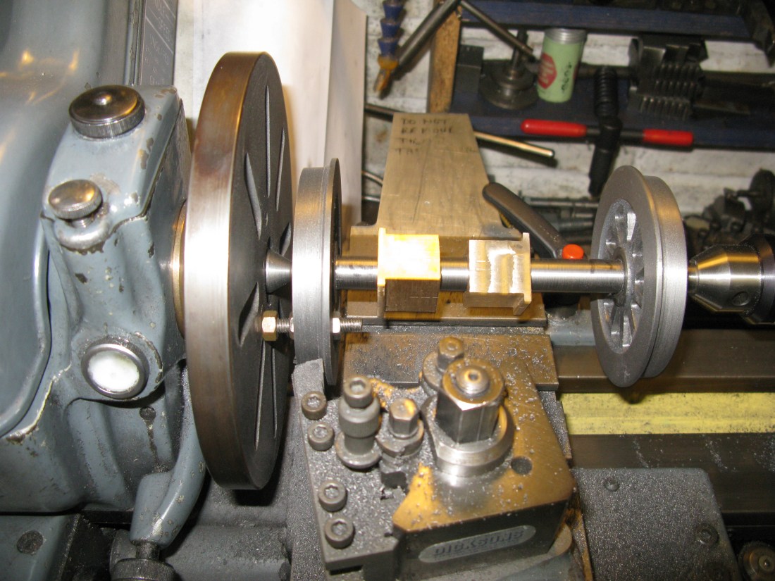
Machining the 20 degree flange
With the wheel sets machined it was off to the paint shop.
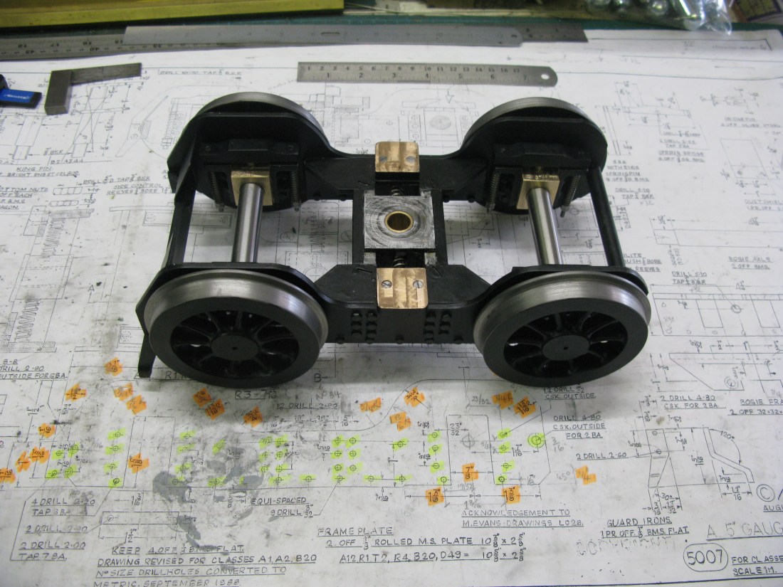
However I did try the wheel set in the bogie first and found that the front wheel set cannot be fitted with the guard irons in place as the there is a foul with the wheel diameter which of course is not there once the wheel set is fully in its horn blocks.
The wheels set having been painted are now fitted to the bogie. The reare set just slides into the horn blocks and the axle block retaining strap bolted in place. The spring hangers are then fitted. I found the spacer that seperates the bridge from the axle block kept falling out during the assembly operation so I resorted to a drop of loctite in the bridge to retain it.
The front set need the guard irons removed first. Hving done this it was just a repeat of fitting the rear set and the guard irons refitted.
There are two dust panels bolted to the front stretcher. They are just 20g brass sheet with a slight bend fitted with a couple of 8 BA set screws.
the finished bogie
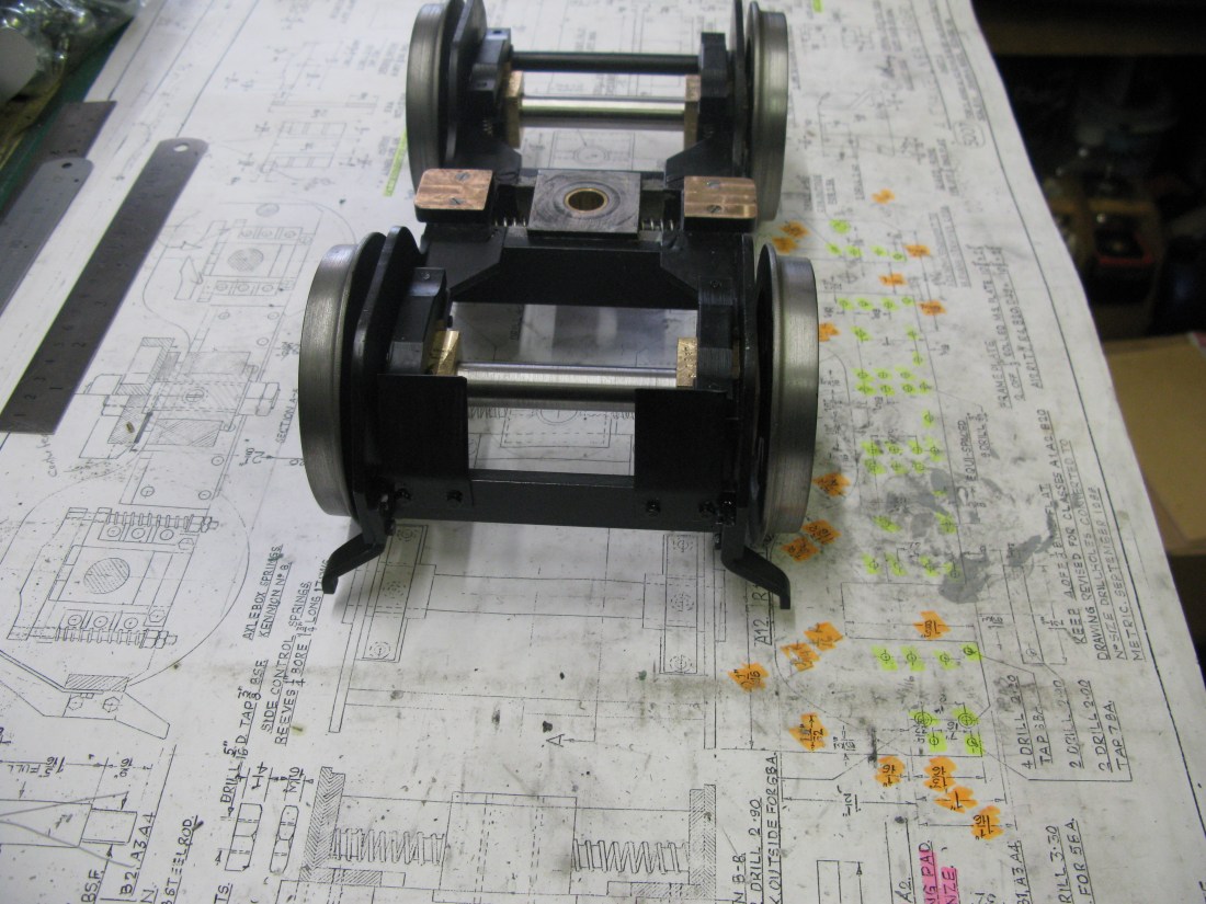

Bogie fitted to the chassis. Just the retaining nut to put on.
