So why do these at this stage of the build ( a running chassis on air). Well all the front end shafts and levers are inside the frames and at the very front under the cylinders and the front bogie cannot be done/ fitted until all the drain cock levers are in place.
There are three shafts within the frames all 5/32″ diameter. The first is under the cylinders and protrudes beyond the frames for the extended lever to fit onto for operating the outside cylinder draincock. There is a middle lever for operating the middle cylinder and and a further lever to connect to the second shaft.
The second shaft is at the top of the frames and and it sits with no extension outside the frames and has the operating lever to connect to the front shaft and the third shaft which is further back which is much longer and extends on the outside of the right hand frame under the running board and from there its levers connect to the back of the loco in the cab for the operating lever.
The first problem became evident as the front shaft cannot be fitted with the cylinders in place as the cylinder bottom diameter cover the frame holes. The solution to this was to make a split shaft in the form shown below.
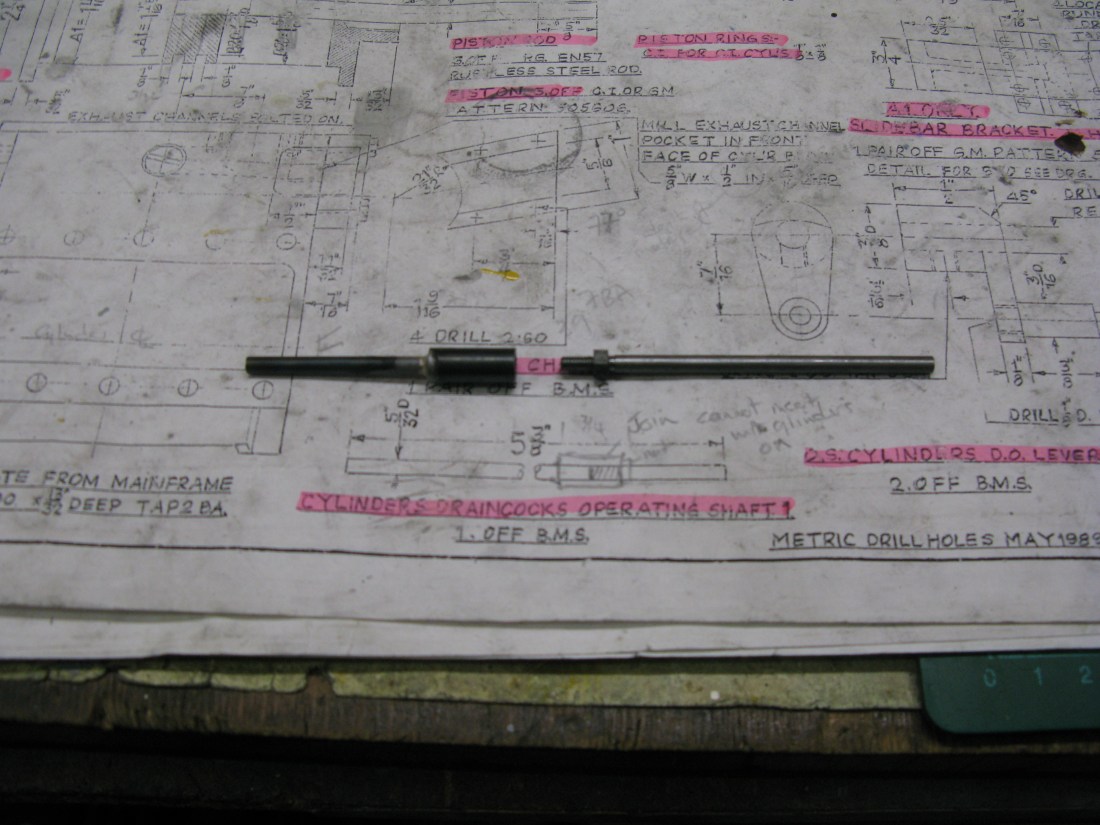
Split front shaft.
However even this cannot be fitted as there is insufficient clearance to fit the shaft pieces from the inside for them to be screwed together.
The problem of insufficent hole clearance to allow the split shaft to be screwed together.
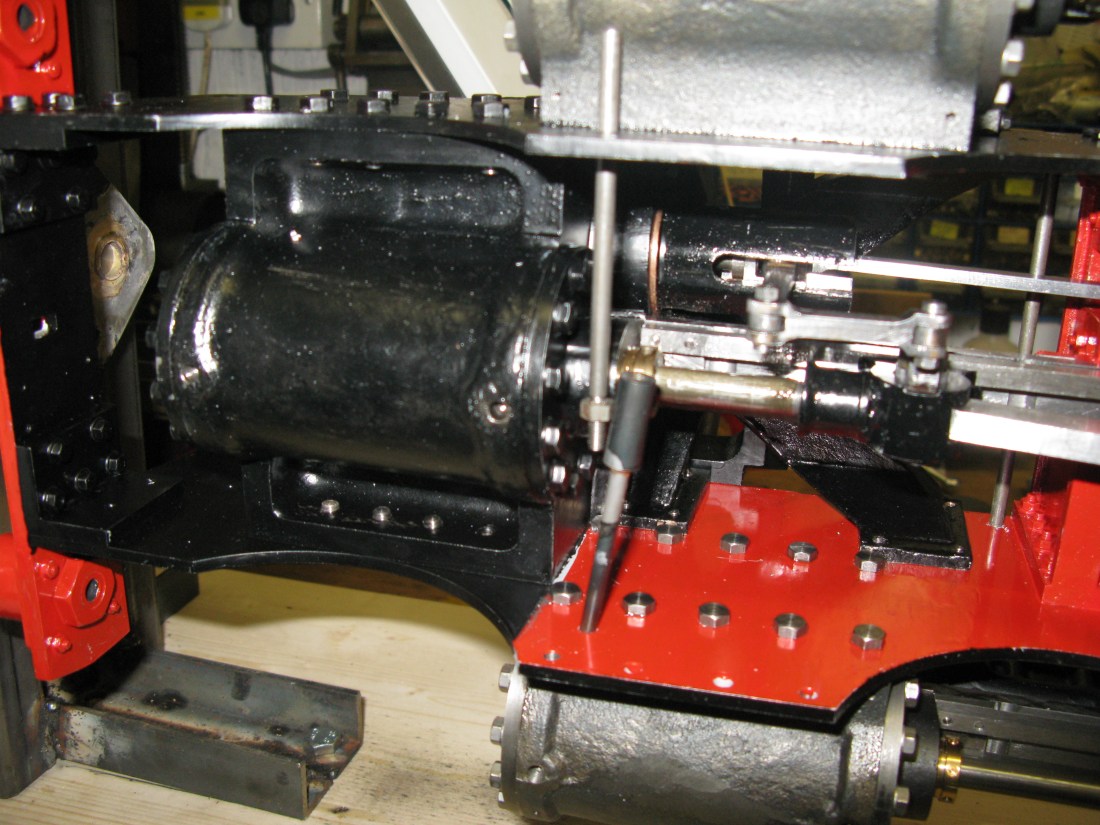
The solution to this was to open out the hole in the frame so the shaft could pass through the frame and fit a bearing bush to make the bearing surface good again. Opening out the hole was done using a small grindstone in a right angled head fitted to a Dremal drill. The result was not a perfectly round hole of course but with the bushing being a reasonably good fit (to be loctited in position when all the levers are fitted) the shaft can be fitted to run true.

The fitted shaft and bushing
The operating levers are an assembly of a bush and lever silver soldered together. The levers are held on the shafts by grub screws. At this stage I am only fitting the levers from the front shaft down to the one shown above to enable me to complete the drain cock assembly so I can eventually mount the front bogie which I will be making next.
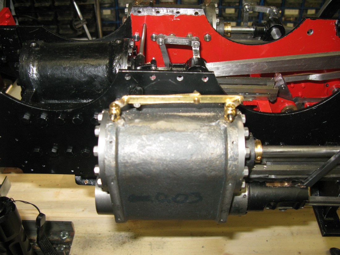
The first cylinder levers fitted. The drain cocks are commercial as quite honestly the cost of them far outweighed the time and effort to make them. They are of the tapered cock type.
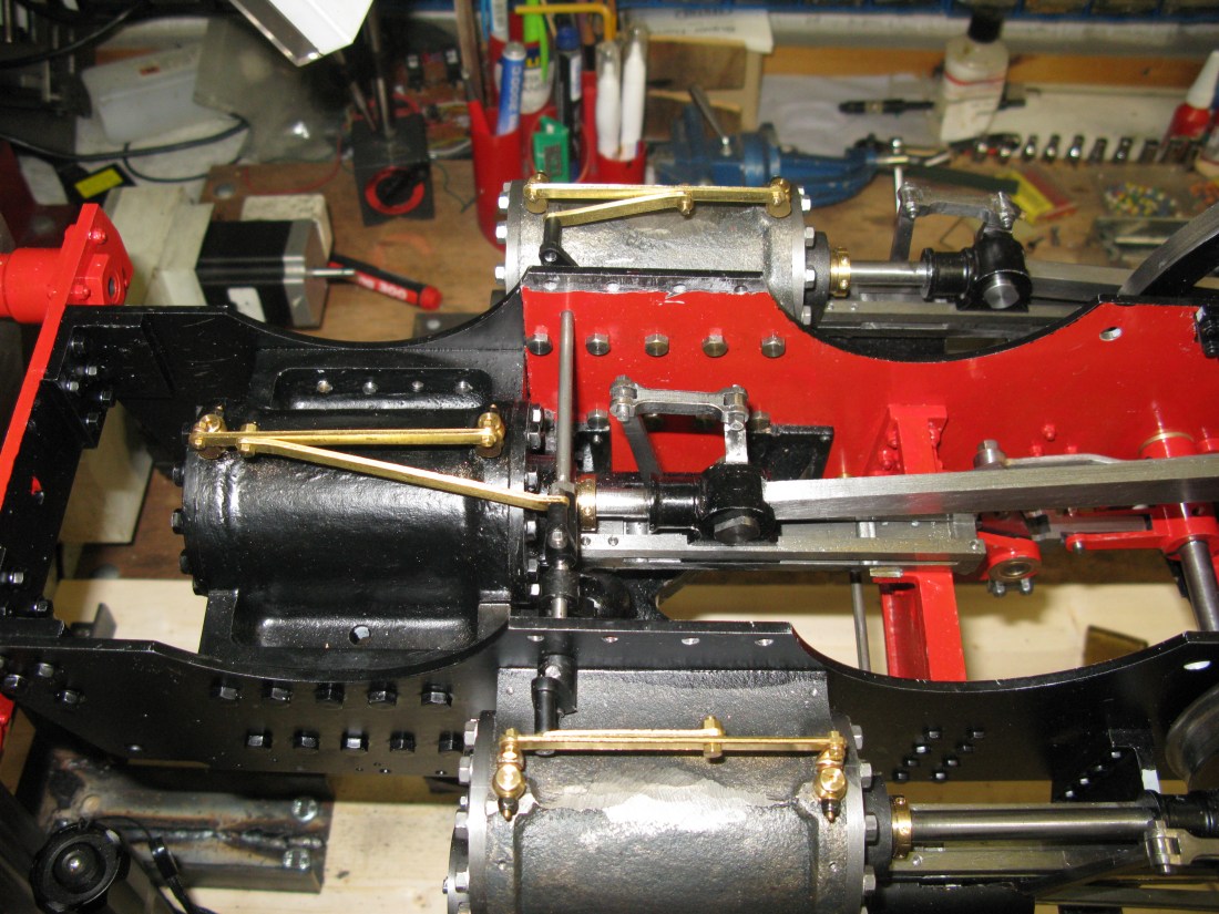
All three cylinders done. The brass levers are 1/16″ thick half hard brass 3/16″ wide cut from sheet.
With all three cylinders fitted the force on the operating lever is quite high as it only 1/2″ long and I found the single grub screw attaching it to the shaft was prone to sliping. It has all got to be dismantled for the levers to be painted, so next time it is assembled I think I will apply some Loctite to the shaft to provide some additional grip.
The drain cocks cannot be finally fitted of course as the cylinder cladding has to be fitted first.
With the cladding on the drain cocks and levers have now been assembled but in doing so I discovered one of the operating levers under the cylinder was still slipping despite thinking it was held firm. In trying to tighten the grub screw, the screwdriver slot would not take the load and one side came off meaning of course that the grub screw cannot be tightened or taken out! The only recourse was to attempt to drill it out in situe. This was not at all successful. I ended up trying to enlarge the hole and retap it a size up and this was a failure too. So in the end I drilled right through the operating shaft into the other side of the boss and fitted a 1/16″ pin with loctite. That solved the problem but left a rather unsightly hole where I had been attempting the repaire. Fortunately it is out of sight. I might put some epoxy metal in around the pin to mask the damage.
The drain cocks being commercial ones have no means for connecting the extension pipes so I had to design a suitable pipe fitting adapter which meant opening the drain cock hole to accept an 8BA tap and making a adapter to take a 3/32″ pipe that screws into the now 8BA tapped hole. The adapter is made from 1/8″ brass hex. It has a No.55 drilled hole through it which matches the bore of the pipe and has a 6BA thread to take the pipe fixing nut. Now there is no room for a conventional nipple so the end of the pipe is slightly flared and this fits into the thread of of the fixing nut as it screws onto the adapter and eventually comes up aginst the coned shape of the adapter.

It seems to work OK, will it leak? … I’ll have to wait and see.
Thr drain cock rodding from the outside lever underneath the running board to the cab lever is split into two. However before starting on this I fitted a support bracket under the running board for the axial lever rod as I was unhappy with the force required to operate the drain cock and that it might tend to flex the axial rod at this point. It’s not prtotypical as far as I know but it gives something less to worry about.

Close ups shows the dust!!
The rod from this point runs under the running board to a supporting lever about 10 1/2″ back. This lever is hinged from under the running board so it can swing. Whilst the GA drawings show its existance, there is not a detailed drawing of the swinging lever. This lever has to connect to two rods via clevises so I came up with a triangular lever design that allows each clevis to have its own connecting pin rather than have one clevis having to straddle the other on a single pin.

