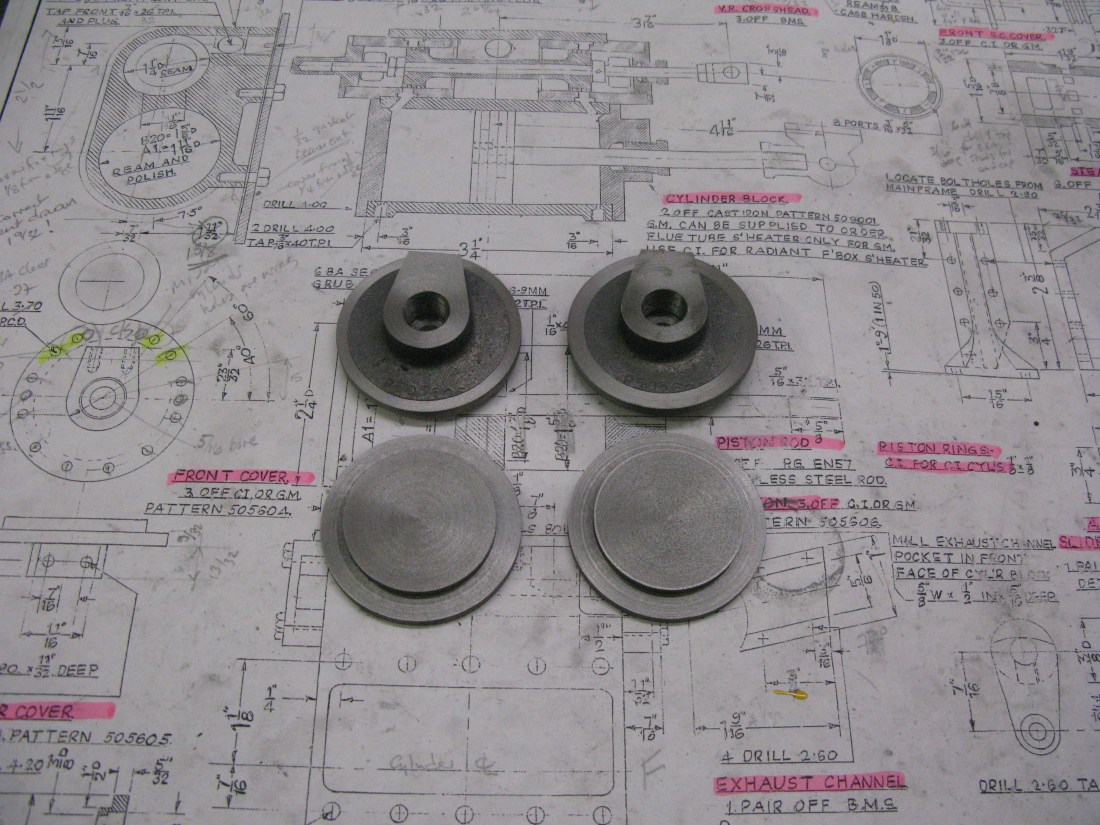
The first cylinder block to be machined is the middle one as I wanted to fit it between the frames before painting the frames. My cylinder blocks are cast iron although gun metal versions are available.
Examining the drawing to obtain an understanding of what was to be machined and also to understand the steam exhaust arrangements etc I noted that the K exhaust casting had fixing holes for attachment to the frames that were not on the frame drawing. These will now have to be drilled in the frames in situ. More of this later.
I found it necessary to refer to the outside cylinder block drawing to gain an understanding of the middle cylinder block detail in respect of the porting for the main cylinder and also for the detail of the piston valve liners. There is also a casting called the valve rod guide which is drawn but not shown on the assembly drawing which has a plain end cover for the valve rod. Maybe I will find out the answer to this puzzle later. In any event is does not affect machining of the main block.
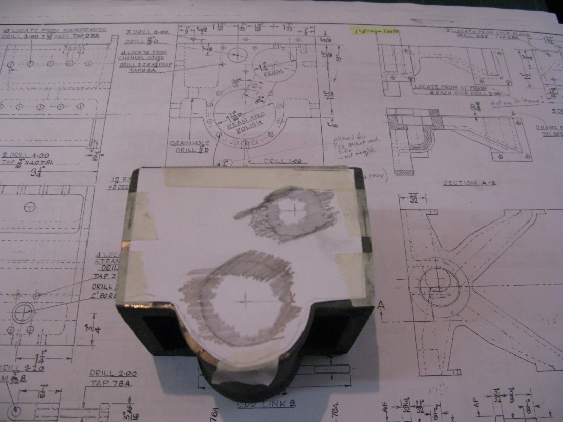
The first task was to establish the position of the cast holes in relation to the casting to see what material was available to machine off. It was also necessary to establish where the critical edge/surface was in relation to these holes that would form the datum for all measurements.
To achieve this I taped a piece of paper of one end of the casting and using a lead pencil used the simple proces of scribbling around the hole edges which leaves a nice crisp outline of the holes. From this I was able to establish the approximate position of the hole centres and hence how far they were away from the various edges. The critical surface I found to be the top surface and its lip to which the K exhaust casting bolts. This was because the lip thickness was undimensioned and from the drawing appeared to be 7/32″ thick and its height (dimensioned) at 5/16″ from the top surface bought the piston valve hole 1/16″ or so below the established rough centre of the hole. So only a light clean up of the lip was in order.
The block was mounted in the vice on the mill and the lip machine sufficient to give a clean top edge and clean inside edge that would allow a sensible clean up cut to the block front at a later stage in machining. The top surface was then machined down to 5/16″ below the lip top surface.
The next machine set up used the angle plate and the block clamped to it with G clamps to machine the first side, then swapped around to do the second side and then the front and back resulting in a nice square block that slides into the frames.

Now I should have said that I did not follow the drawing exactly which calls for the block to be 1/16″ narrower than the frames and the 1/32″ gap each side taken up with a gasket. I could not see a reason for a gasket in this position as there are no steam joints so I chose to make the block 4 1/8″ to fit the frames without the gasket.
Having machined the block all round the next task was to machine the bores for the piston and piston valve. The block was mounted on parallels on the mill table (so as to let the boring bar clear the bottom of the bore) and clamped to the angle plate with G clamps. Using a centre finder the top and side edges were located and the DRO set to zero in the X and Y planes respectively. An adjustable boring head was used to machine the bore. Here came my first problem. The quill of the mill has a travel of 3″ and the bore is 3 1/4″ long. The second problem was the boring bar that came with the head was not long enough to go through the bore. This problem was overcome by using a lathe boring bar that fitted the boring head and was long enough to clear the bore without being too long with the attendant problems of springyness. The restricted quill travel meant that two bites were required the second being done having removed the tool from the bore and then winding the knee of the mill up by 3/8″ locking it and continuing with the bore. This approach sufficed for doing the roughing out.

I did wonder if I could have used the lathe for boring but the block is really too large to chuck mount and attendant centering difficulties did not appeal to me. Mounting the block on the saddle was also a no go due the centre height restriction over the saddle and having an adjusting chuck mounted boring bar was a luxury that I did not have any way.
Having bored out the cylinder piston bore the next task was to hone the walls as the tool finish is not smooth enough. I have a sprung three legged hone with 2″ long stones that I used for this task. The use of a honing oil is I think essential as the stones will glaze otherwise. A very light oil or even parafin can be used. I prefer an oil as the residue will be all over the mill table and alternative water based products may well cause rust if not thoroughly dried out. However I had no light oil in sufficient quantity so I used parafin.
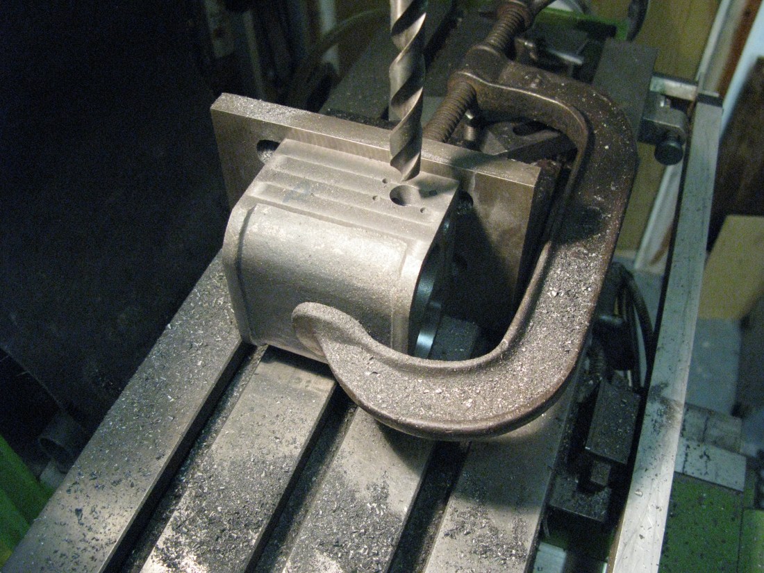
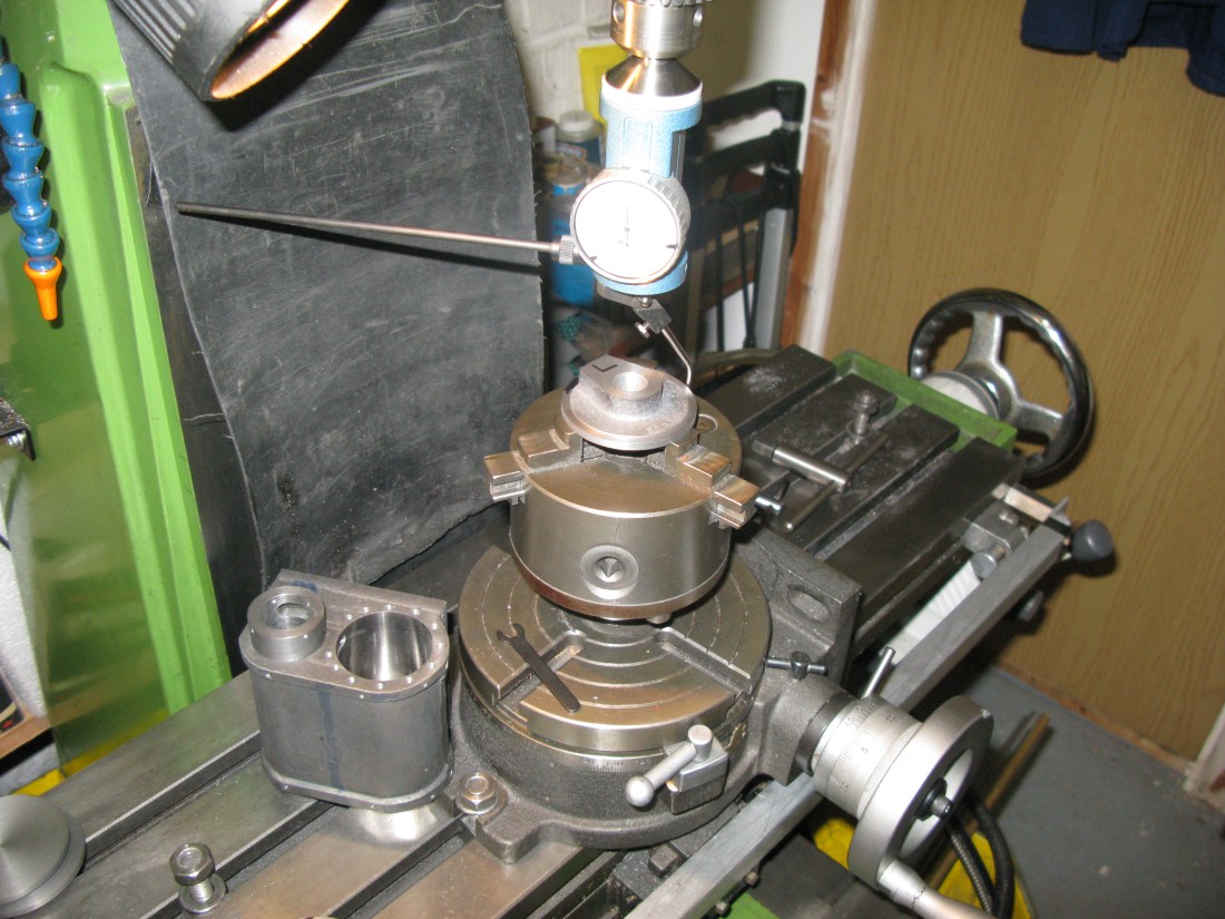
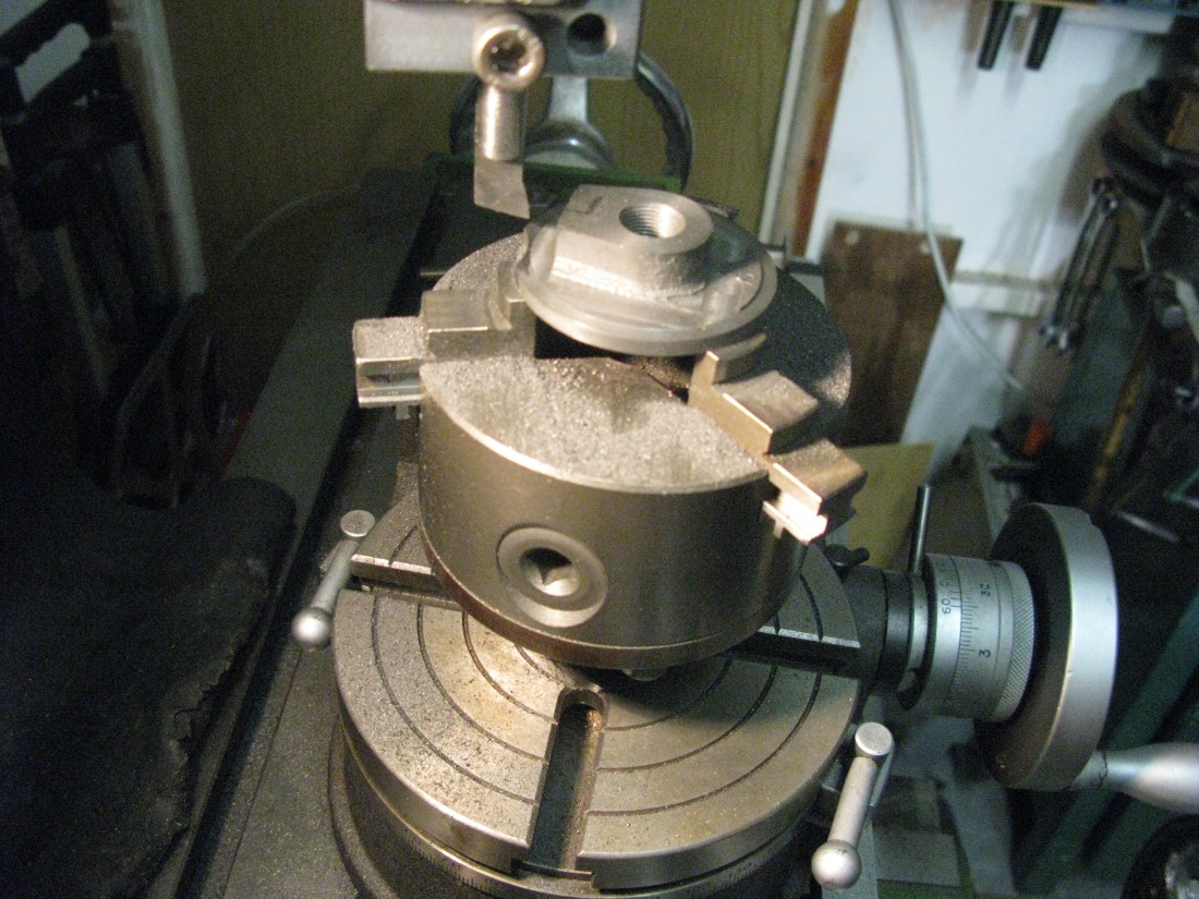
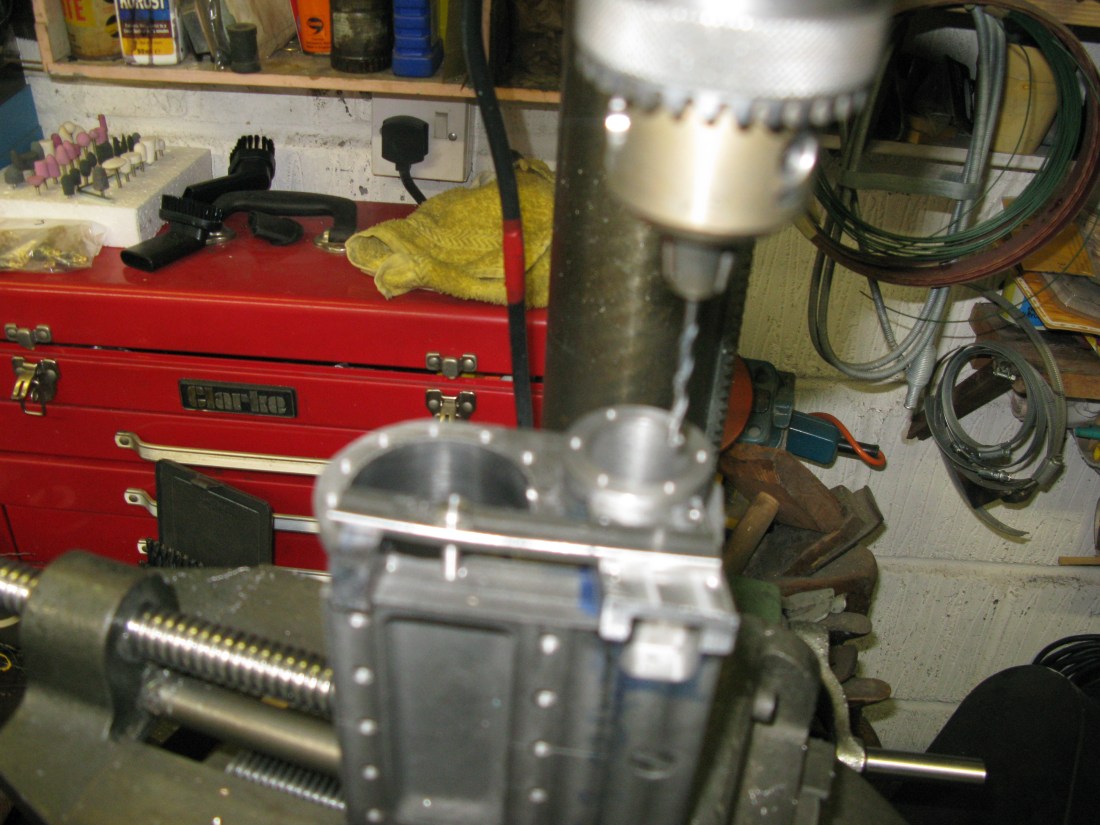
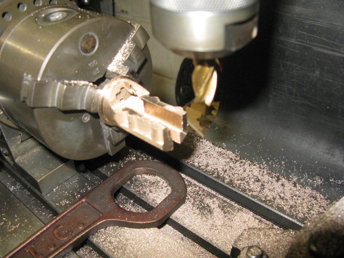
As a break from honing which is a laborious task I drilled the exhaust steam way hole and the holes for the fixing bolts for the cylinder cover and valve chest steam exhaust cover. To get the X and Y cordinates for the 12 holes for the cylinder cover I just went to the internet and searched for a Pitch Circle diameter spacing program and entered the dimensions on line and got a table of the X and Y coordinates in seconds. The hole dimensions for the valve chest cover were taken from the dimensions drawn for the cover and transposed to the cylinder block as the block drawing just says “locate from cover”.

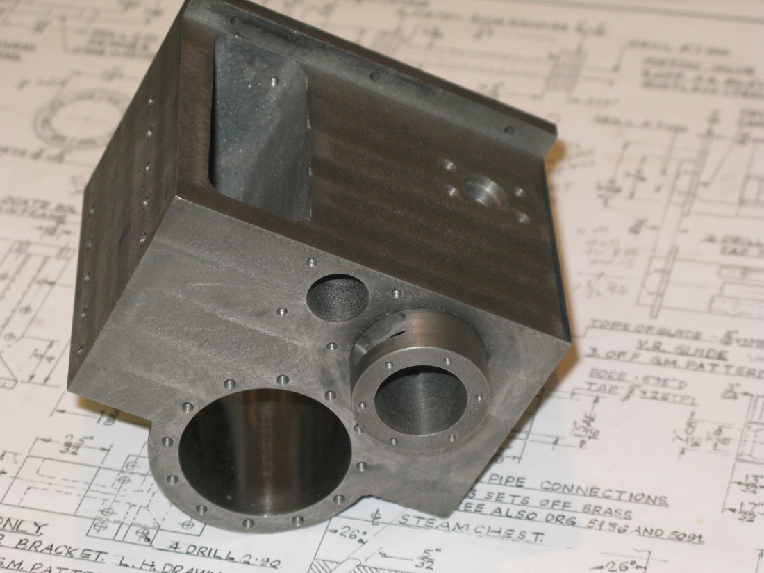
In the picture above the partially honed cylinder can be seen with its imperfections. These have to be removed. Which eventually was done.
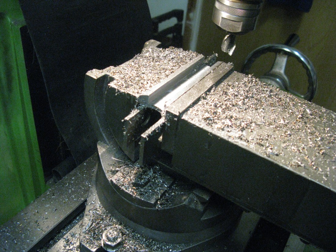
Next came the drilling of the 10 fixing holes on each side. Using the measurements from the frame drawing and the mill DRO the holes were drilled No. 26 for tapping 2 BA and yes, they did all line up with the frames.
Then turning the block over and aligning the edges with an edge finder to zero the DRO the holes for the cylinder cover were drilled using the same XY coordinates as the other side. I then noticed that the fixing holes for the K exhaust were not shown on the block drawing (other than the three in the top lip) as there is not a drawn view of this side so the fixing holes have to be transposed from the K exhaust casting drawing to the cylinder block. The holes are No 43 taped 6 BA although this was gleaned from the K exhaust hole being No 34 (number equivelent of the metric size given).
The holes for the steam entry were a straight forward drilling exercise having located the centre of the steam hole using the edge finder and DRO settings. The dimensions having to be obtained from the steam pipe flange drawing.
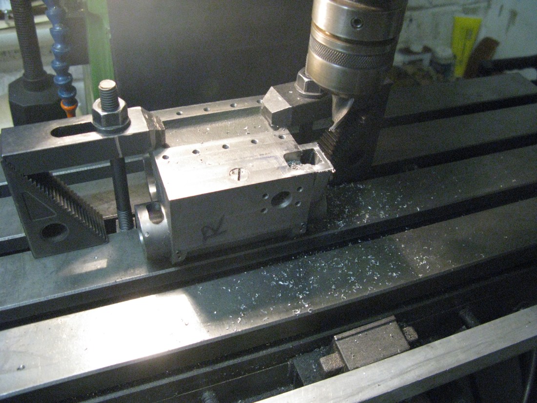
The port into the cylinder from the steam chest is shown as being 5/32″ x 5/8″ at an angle of 26 degrees. It is not clear if this is a slot or four 5/32″ holes. I suspect it is a slot which is not easy to machine. The slot is also at an angle of 26 degrees from vertical. The set up I used was an angle vice set to 26 degrees to hold the block and then set the block at 26 degrees in the vice using a precision angle former. The drawing shows the slot as being 5/32″ back from the edge of the block and I then realised that the slot angle and size would break in to two of the cylinder block end cover fixing holes which were drilled 1/4″ deep.This means the studs in these position will have to be sealed to make them steam tight.
To drill the slots I first used a 5/32″ long series slot drill to obtain a flat surface for the drill to start in the cylinder bore. As I was going to drill 4 of 5/32″ holes to make the slot four flat spots were made. To find the centre of the cylinder as a reference point I measured the cylinder centre line distance from one cylinder end cap fixing stud hole centre and found it to be 3/16″. I thought this scaled measurement from the drawing to be sufficiently accurate. Using the number 43 drill in the stud hole I could then find the edge with the 5/32″ slot drill and from there find the centre of the cylinder bore. The four flat spots were then milled. This was followed with a long series centre drill and finally the long series 5/32 drill.

The resulting slot is not a perfect alignment with the edge of the cylinder as the geometry of moving the X axis away from the centre gives a curve which if taken to its limit would end up on the edge of the cylinder block. The valve guide steam chest ports have ample clearance to accomodate this.
I chose to leave the ports as 4 of 5/32″ holes and not attempt to machine them into a slot. I reasoned the very slight reduction in port area was not significant………… after a sleep I had second thoughts and decided to file the slot out as it did not look right and was a “lazy man’s” solution. I feel better about the end result.
The next task was to tap all the holes. That took a day to complete.

The valve guide liners will have to be fitted before the cylinder block is bolted between the frames as they are a press fit in the block. The drawing indicates they can be either phospher bronze or cast iron. I am uncertain about a PB liner in a cast iron block but having PB has the advantage of one liner not to worry about rusting. Also is the PB liner fit compromised by any differential expansion? Don’t know. I need to cast around and get some opinions.
A couple of sleeps and I concluded that the alternative on the drawing was not a true alternative but probably meant use PB for a gunmetal block and cast iron for a cast iron block which seemed most sensible. So I purchased a stick of cast iron from which to make the valve liners.
The drawing for the liners has a couple of peculiarities. The first is an end view which is a couple of circles but with four C/S screw holes for 7 BA clearance set at 45 degrees to the vertical/horizontal otherwise not dimensioned. The sectioned views do not show them, which is fine if the section does not occur at the screw positions although the section markers are not drawn. There is no explanation of their purpose. Looking at the longtitudinal section of the cylinder block it can be ascertained that perhaps they are the means by which the end caps are held in place although there are no indents in the end cap drawings into which they might locate for security. More of this later. The second peculiarity is the end cap from which the valve rod emerges. The longtitudinal section shows a plain end cap with a typical screwed bush/gland seal. However further over on the drawing is an end cap casting with valve rod guides attached to the end cap. As the drawing is common with an A2 I wondered what was correct. Looking at Tornado, being an A1, it has valve rod guides, so the answer was a valve guide is to be fitted.
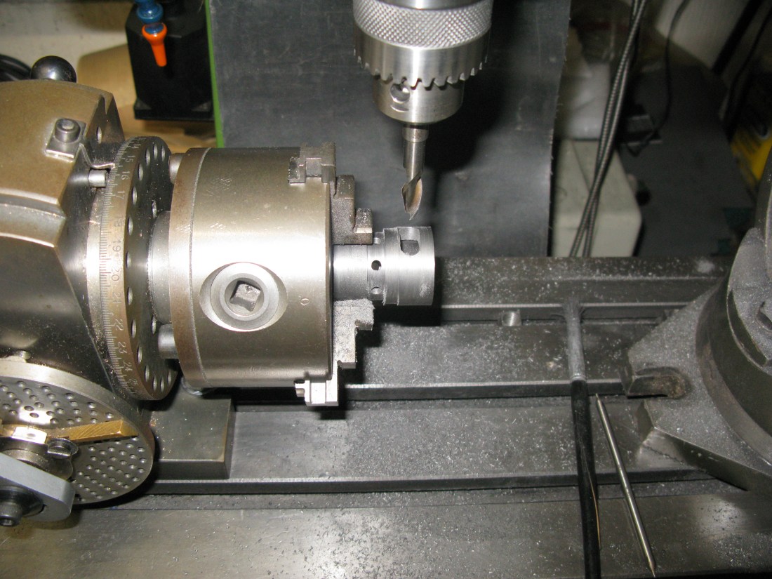
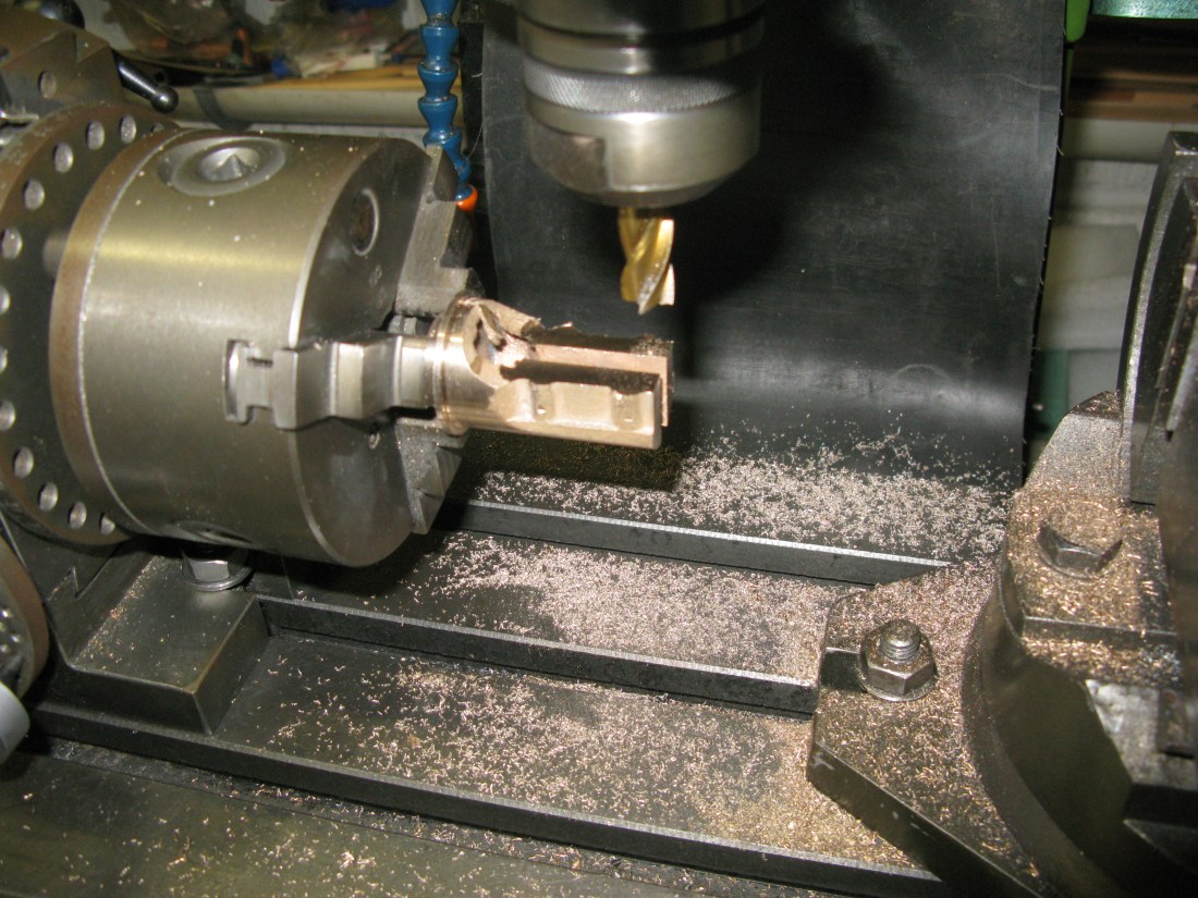
The cylinder liner blank was mounted in the lathe 3 jaw chuck and the external diameters turned down to size and length as drawn including the recess that contains the steam entry ports. The external diameter that fits into the cylinder block being turned to the exact size of the measured bore. This was followed by drilling out first with a 1/4″ drill followed by the largest I had which was 9/16″. Then the hole was opened out by boring to a thou under the 1 1/4″ diameter. The hole was then honed to give a polished finish and arrive at 1 1/4″ give or take 1/2 a thou. With the work still in the chuck the chuck was transferred to the dividing head on the mill. Having located the work centrally under the quill and found the longtitudinal edge the 8 port holes were drilled 5/32″ in the recess and the exhaust port drilled 5/16″ in readiness for subsequent milling to a rectangular shape of 5/8″ x 5/16″.
The chuck was replaced on the lathe and the work parted off to length.
The liner was placed in the mill vice and centred over the 5/16″ hole for the exhaust port. A 1/8″ long series slot drill was then used to machine the 5/8″ x 5/16″ port to complete the liner machining.

It is worth noting at this point that the sectioned drawing of the cylinder block and liner show the exhaust port on the horizontal centre line. However the liner exhaust cap has its exhaust path set at an angle as the exhaust hole in the block is above the horizontal centre line of the valve liner and if the liner exhaust port were to be set horizontal a portion of the exhaust port would be blanked off by the cap, so the liner exhaust port needs to align with cap. Similarly at the other end for the K exhaust casting.
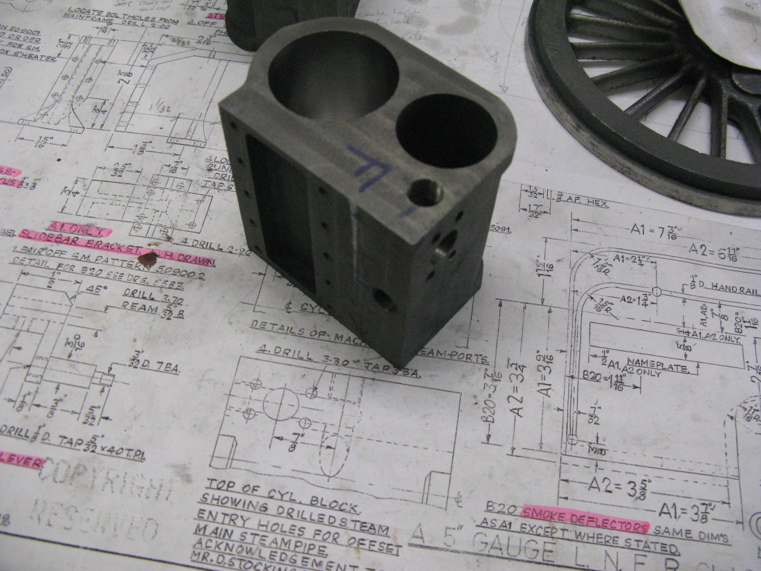
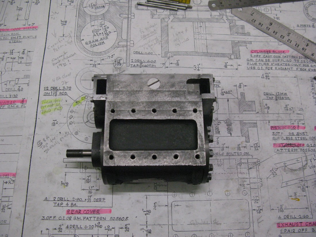
The block so far
The liner that is at the valve guide end needs to have a 5 degree taper turned on its inside face to enable the piston rings to slide into the bore easily. This is not shown on the drawing. Only a small acute angle is shown and this does not work. I had to take my liner out of the block to put the taper in as I found out the hard way when I could not get the piston valve to slide in. The reason it’s this liner is that all the assembly of the piston and its attachment to the valve guide gear is done from the front end. Should the need arise to take the valve out from a completed loco, taper the front liner the same otherwise the valve will only come out from the valve guide end….could be a major task!
I mentioned earlier the 7BA C/S screws were a bit of a puzzle. I concluded that they were there to hold the end caps in place but it was not a solution I particularly liked. The 12″ to the foot version of the A1 had the end caps bolted in place by 6 fixings and I chose to adopt this arrangement using 6 off 8 BA bolts screwed into the liner end. That would be straight forward for the front of the block but the rear caps having valve rod guides meant that the fixings would have to be of a differently spaced and only four of them so these needed to be worked out. As the underside of the valve guide extends close to the edge of the cap there is no room for fixings there so the four tapped holes were spaced at 60 degrees equally about the vertical centre line which means there are no fixings below the horizontal centre line. I wonder how the full size was fixed. (I noted later on other A1 models that the outside cylinders had their valve guides held in place with allen screws rather than the C/S screw. This had the advantage that the valve guide web does not have to be cut away for fixing studs/screws so on the outside cylinders I may well copy this arrangement).
Looking at the future and the assembly of the block, K exhaust and valve rod guide end cap set me thinking if it would easier to make all these and assemble them out of the chassis as access to the fixing bolts was going to be finger juggling stuff. The piston valve would go in from the front anyway.
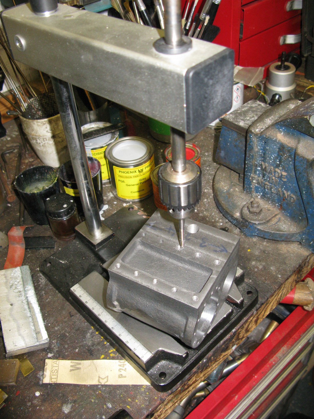
After a couple of months doing other things on the loco I came back to do the cylinder covers. The front cover is a cast iron casting and it is a straight forward turning job. However drilling the holes for the fixing bolts required finding the center of the cover and then using X and Y co-ordinates to drill the 12 holes. I used this method rather than a rotary table for division as that is the way I drilled the holes in the cylinder block and I reasoned if I used the same figures they should all match up, which they did. I also added two 5 BA tapped holes to act as jacking points for removing the cover at some future date. They are an invaluable assistance for removing such covers. I should perhaps mention that finding the centre was relatively simple with the work still in the chuck and mounted on the rotary table on the mill bed as I possess one of those internal/external centre finders that I treated myself to some many years ago.
There is a small section of 45 degree flat to be machined to allow clearance around the port and this was done with an 45 degree cutter. The flat is not dimensioed for its length but can be judged from the port length.
The cover cannot be fully finished until the exhaust cap is made as a small radial clearance is need in the cover to clear the exhaust cap so the next job was to make this.
The exhaust cap is a gun metal casting and it is of a shape that makes all maching difficult. The first and probably the easiest of tasks is to machine the casting flat and 15/32″ thick. This was done by clamping the casting on the mill table machining around the clamps then moving the clamps to another place and finishing the face off. Turning the casting over and repeating the process checking the height from the mill table completed the job.

Next either the outer edge or the internal bore has to be done. Which to do first? I chose to do the outer edge as by using the rotary table and getting the casting to sit as near over its centre as I could do the outer top edge which is straight and the round rim of the bore could be partially done without moving clamps and would naturally give me the centre lines via the DRO readings and tool diameter in use. This proved a bit fiddly to set up but once done the partial machining was undertaken to get the outer rim of the bore to an 1 9/16″ diameter.

Machining the outer top straight edge and partial outer radius

Maching the bore having finished the outer edge.
The clamp restricting the outer circumference being completed was moved and the remainder finished machined. As the rest of the outer is at an angle of 19 degrees I left that till last.
The bore was then machined and many measurements and checks done as I approached the finished size to fit over the piston valve sleeve. I have a set of those sprung loaded internal bore measuring devices but I find as you tighten them up they move slightly to a smaller diameter and no matter how you try it cannot be stopped so I resorted to the good old fashioned inside calipers and feel. The next task was to drill the fixing holes and using the mill DRO this was an easy task. Having drilled the fixing holes and got the bore to the size I thought was right I took the work off the mill and tried the fit over the piston valve liner……..and it was too tight to slide on …pressed on yes, but not slide on so I had to reset the work back on the mill and find the exact centre and take off a thou or two which fortunately went well and the next fit was a success.
Now the front cover could be marked to give clearance to the exhaust cap and a shallow arc filed to suit. This finished the front cover.
The exhaust cap is fixed with 4 6 BA set screws and the pictures below show it complete and in place temporarily as the faces of both the cover and cap need to have sealant applied before finally bolting in position.

As these two componants are metal to metal facing and machined surfaces I am using Loctite 510 as the gasketing material. It is a high temperature liquid sealant rather than the silicon type.
Moving back to the rear cylinder cover which is a cast iron casting like the front but with the appendage for fitting the slide bar and of course the bush arrangement for the piston rod. The casting comes with a sacrificial boss on the bushing side for mounting in the chuck. This enables the main body to be cleaned up to the overall diameter and then take a cleaning cut on the inside face as far as the bushing boss allows and from this the thicknes can be determined and machined by facing off. Finally the diameter that fits into the cylinder bore can be turned. All fairly straight forward other than getting the size to fit the bore right. I used the internal spring calipers and feel to determine the size. The piston rod bore of 5/16″ was then done with a pilot drill followed by the 5/16″ drill.
The chuck with work was then transferred to the mill on a rotary table and centred under the quill and the 12 fixing holes drilled 4 BA clearance using the same X and Y co-ordinates used for drilling the block making sure the top of bushing boss was square (in unmachined state) with the X travel of the mill table.
No more work can be done with the cover in the chuck so it was removed to check it would fit the block ……well it would press in but not slide in. The cover was put back in the chuck and the as a three jaw chuck does not center accurately I used a flat file to take off the thou or so that was needed for it to fit into the cylinder bore. At this point I discovered two errors. One the cover fixing holes are not the same as the front cover. The two top holes are offset to clear the slide bar. This was not a problem as I could use C/S screws in the top two holes ( Lesson – examine drawings more carefully!). The more serious problem was the fixing holes did not match the cylinder block as they should. I could see no explanation as to why they did not exactly match and there was nothing else to do but file the holes to allow the screws to fit.
With the cover now fitting on the cylinder block it was mounted in the mill vice so that it sat square with the table and the cover temporarily bolted in place. This allowed the top of the boss to be machined for the slide bars to ensure they would sit parallel with the block. The opportunity was then taken to saw of the sacrificial boss and machine the boss down to its correct height above the cover. The outside surface was then cleaned up to the facing surface initially put on when starting. To clean up the facing surface around the boss the cover was removed and I used a file to finish off the clean up process.
The final task was to machine the thread for the gland nut which is 9/16 x 26 tpi. Not a thread I have in the tool box so a purchase of tap and die was necessary. (I did consider using ME 32 tpi but I did not have 9/16″ in that size either). With the cover set up in the three jaw chuck (and running as true as I could get it) the central hole was opened up with a 1/2″ drill to a depth of 5/8″ and then bored to the diameter to suit the 26 tpi thread, tapped and job done. This left just the two fixing holes used to bolt down the slide bars to be done and make the gland nut.
The piston rod gland was made from brass. It is threaded to fit the cover and has 6 holes around its periphery for a bar to tighten into the cover. Having turned the brass down to the required diameters it was threaded using a die and then drilled and reamend 5/16″

Drilling the 6 bar holes in the gland
Outside cylinder blocks
I decided to do both cylinder blocks at the same time so any set up arrangements could be used for both.
The cylinder blocks are cast iron and as usual with this material I have a love/hate relationship. It is lovely to machine but the mess is dirty and I use a face mask now when machining as the dust is not nice.
The first task is to get flat faces to the back and ends from which subsequent measurements can be made. The first face was a block end and this was rough machined using the mill vice.

It was then turned over to do the other end.
The next face was the back of the block, again using the mill vice.

These rough machined faces were not perfectly square to each other, not far out, but they would be trued up on the final machining.
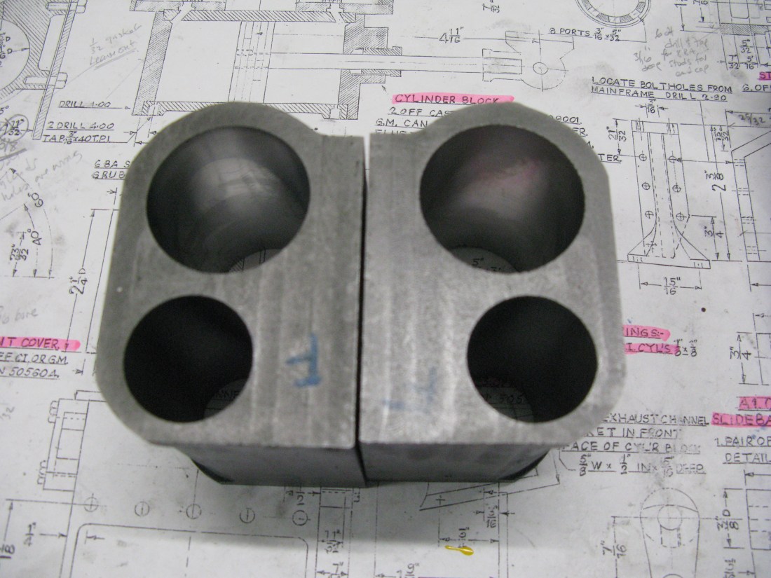
Having got workable surfaces I then found the rough centres of the bores. To do this I used masking tape over the ends and outlined the holes by gentle pressure on the edges.

From these outlines I could establish the rough centre lines for the bores and having found those I could then establish the edges of the rear of the block and the flat top safe in the knowledge that the bores would end up being able to be machined more or less centrally to their cast position given that the centres of the two bores were more or less 7/32″ apart horizontally and 1 11/16″ vertically as they should be.
I came upon a potential problem when checking the distance of the main bore from the back of the block. The drawing was dimensioned as 1 11/32″ but it was actually drawn as 1 9/32″. Checking against another drawing which showed the block but was undimensioned it was drawn at 1 11/32″ so I assumed the dimension to be correct.
The cylinder block is drawn mounted with a 1/32″ gasket. As with the middle cylinder I chose not to use a gasket. So the finished dimension has to 1 3/8″.
The first final machining was the back surface, but first I machined a shallow flat on the ribs that take the cover so that it could be bolted flat on the mill bed.

This done the back was machined down to the scribed mark measured from the centre of the piston bore.
This was followed by using an angle plate to machine the block ends to achieve the required length of the block at 3 1/4″ and the block was clamped up against parallel bars to give clearance from the angle plate for the cutter.

This machining produced square surfaces. However it also caused the overall length to be short by 10 thou for one block and 30 thou for the other block. This is not a problem providing the centre line of the block is used as the datum for all port and fixing bolt positions. The front cover can be reduced in thickness to accomodate any possibility of the piston hitting the cover if necessary. Also care is needed when making the valve sleeves to ensure the ports will align with the block. There is a generous slot in the sleeves so I do not anticipate any problem with that.
Finally the top surface was machined flat.
The cylinder bores were then done using the following set up ensuring the block was upright using a square against the top surface:

The two side clamps hold temporary fences to prevent any possible sideways or tilt movement occuring whilst machining. The block is clear of the mill table using a parallel bar underneath against the angle plate.
The honing process for the main cylinder bore uses an amateur hone, i.e. a centrally sprung three stick hone. It is a long process as initially the new hone stones are square and that means only the edges cut and usually only one edge as the turning forces and the simple pin arrangement holding the stone in place causes the stone to twist. The recomended honing RPM is a function of material, stone width and number of stones. For cast iron starting on a “rough” cut bore (here “rough” is used to mean not a perfect smooth finish) the speed works out to between 300 – 760 RPM depending on whether the cast iron is “soft” or ” medium” hardness. Not having a Rockwell measuring apparatus I have no idea what my castings are so I opt for the middle road “medium” and run at 410 rpm. (The harder the material the slower the speed). Also I have no idea what the grit formulation of the stones are as the recommended for cast iron is a silicon carbide based stone. So the process becomes a bit “hit and miss” and frustratingly long.
After quite a few days of honing activity I still have not finished one cylinder. The stones become blocked quite quickly even with parafin lubricant. Previous cylinders that I have done have eventually honed OK so maybe these cylinders have a different cast iron composition. Anyway I have decided to put the cylinders out for professional honing. Life is too short! Should have the cylinders back withing a couple of weeks.
Cylinders are back with two nice shiney main bores.
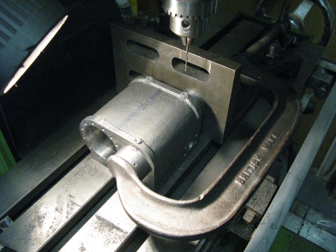
The first holes to be drilled in the cylinder blocks were the fixing holes to the frames. The hole dimensions need to be transferred from the frame drawing.

The set up is shown above. Using the DRO the mill table was set to zero against the angle plate and then the front face of the block. As I already had machined the bores to be 2 1/2″ from the top (against the angle plate) and I knew the length of the cylinder the setting out of the cylinder block holes could easily be done from these two datums.
The next set of holes were the cross drillings for the steam entry.
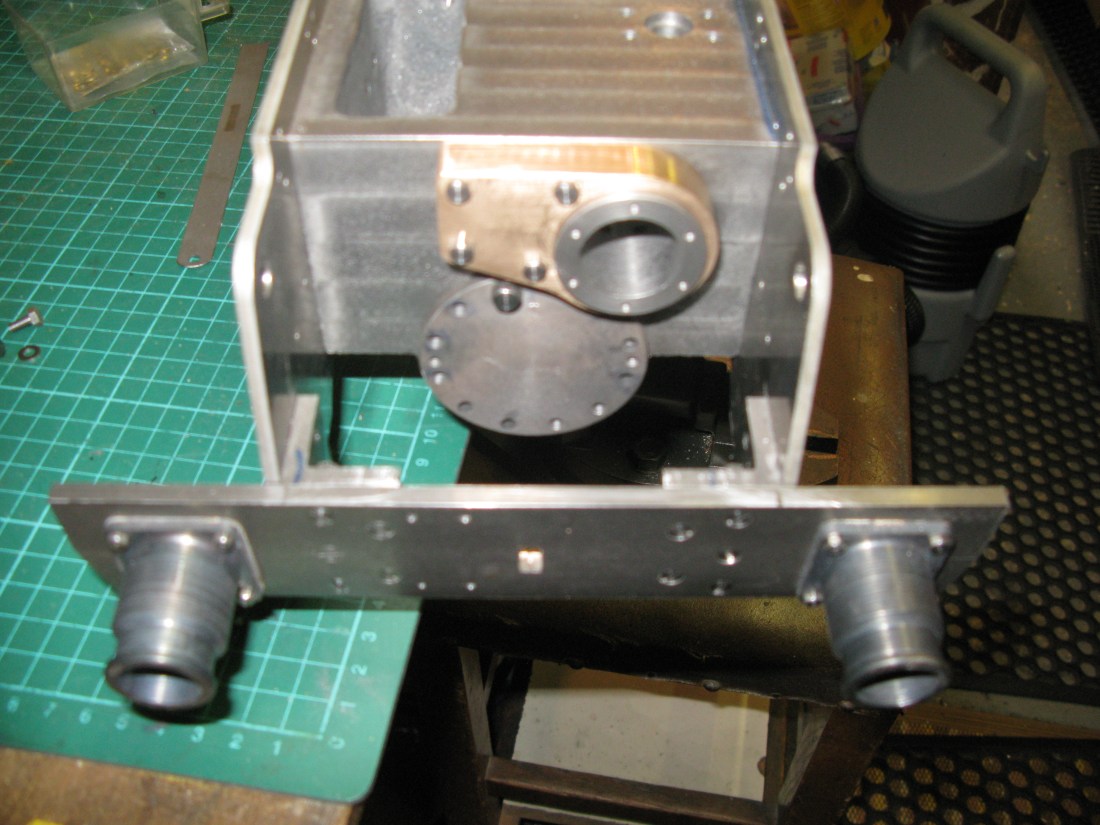
These were again done by use of the DRO settings from the angle plate and front face datums. The photo above is the final hole for the steam inlet to the cylinder with its four fixing points for the flange.

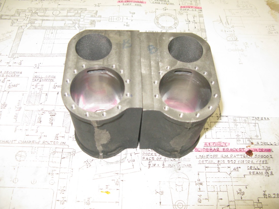
Both cylinders with the cross holes all drilles but not blanked off.
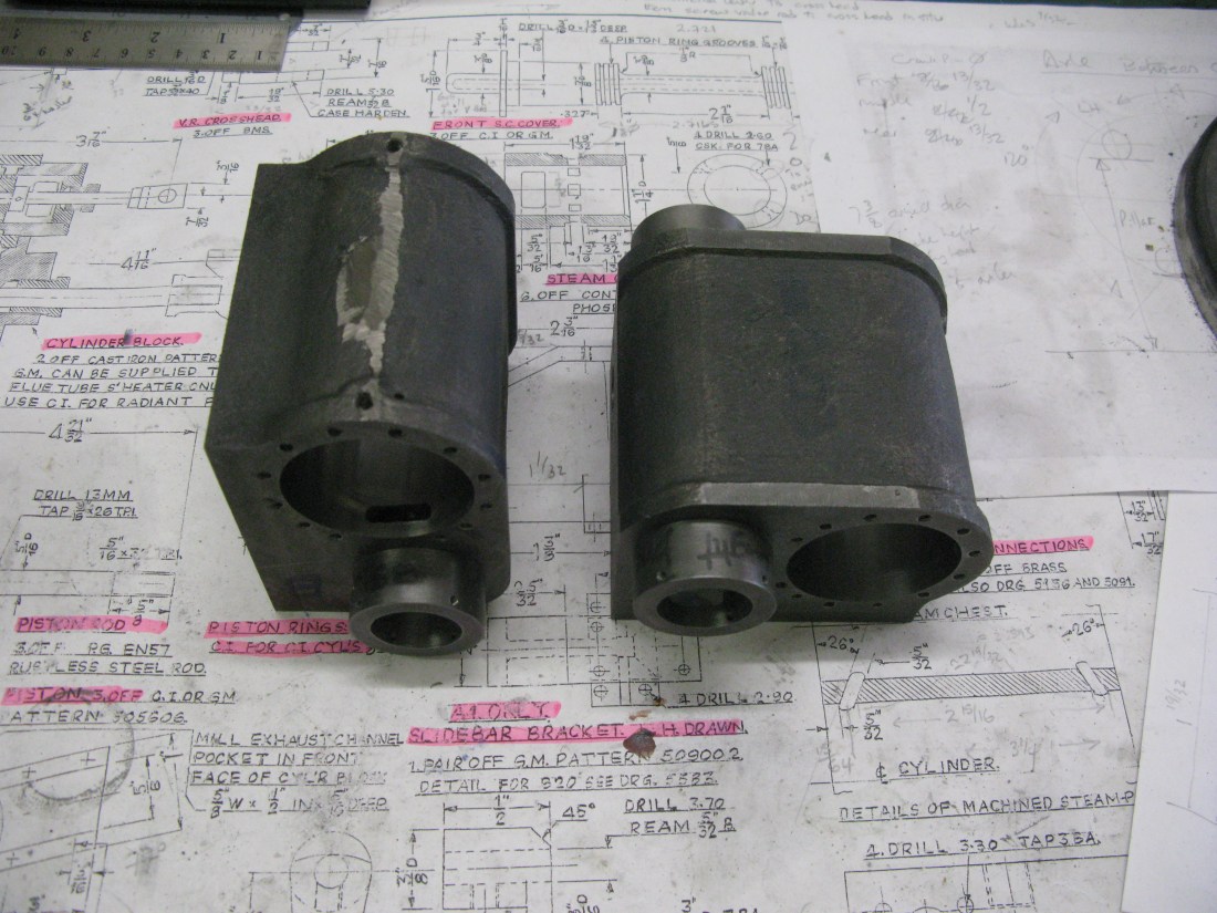
A cylinder above the drawing showing the cross drillings.
Why is there a wheel showing? …… I was thinking ahead about how to ‘third’ the wheel driving pins using calculated height gauges before the cylinder blocks came back from being honed. More about this much later.
The cross drillings that are to be blanked off are threaded 3/8″ x 32 ME. The drawing calls for 3/8″ x 26 but I had no taps that size.
Next, the holes for the cylinder end covers drilled to be tapped 4 BA. The holes on the back face have three different PCD settings. There are two holes at 40 degrees and two holes at 60 degree starting angles and the rest are at 15 degree starting angle. The gap produced by this arrangement of holes at the top of the cylinder bore is there to clear the slide bars.

Centering the bore before drilling the cover fixing holes
The front cover can be drilled for all 12 holes with a starting angle of 15 degrees. This will just about clear the valve guide liner. I will have to wait and see if reduced head set screws will in fact fit OK. I suppose I could have drilled the front the same as the back which would certainly have given clearance but to my eye the asymmetric arrangement did not look right.

The back cylinder cover holes drilled …. note that asymmetric top four holes
Tapping the numerous holes on a well cluttered bench!
Having drilled and tapped all the holes I started to set up for the drilling of the port between cylinder and valve chest only to realise that I had forgotten my middle cylinder experience where the port broke into two of the cover fixing holes! I had made the same mistake for the front cover drillings. That is why the holes are at 40 degrees and 60 degrees so they miss the port. Doh! Rather than rely on the cover bolt to be steam tight I decided to plug the holes before machining the port and then see if there was sufficient room to fit in another two fixing holes.
To machine the ports the cylinder block is set up in the vice tilted at 26 degrees and the block at 7 1/2 degrees in the vice jaws. This sets the angle of the port from cylinder to valve chest and on the centre line between the bore of the valve chest and cylinder. It’s the same set up as for the middle cylinder (see photo further up the page for the middle cylinder). First the edge of the cylinder bore is found simply by using a centre drill with its centre on the edge of the bore. Then the centre of the bore is found simply by using the height vernier of the mill to find the lowest point on the edge. These measurements are not precise as there is no need for precision for the steam entry/exhaust position of the cylinder. The valve sleeves provide the precision for valve events and the sleeves have a good clearance to cover the cylinder slots.

Using an edge finder to locate the face edge at the bore edge …..eventually just used a centre drill. The two plugged holes can be seen as well.
The slot is supposed to be 5/32″ from the face and 11/16″ wide and 5/32″ deep. The first process used a long series mill to put a flat at four points where a 5/32″ drill could be used to start creating the slot. The flat is needed as even a centre drill wanders on the honed angled surface. The four flats then had their centres drilled with a long series centre drill followed by a long series 5/32″ drill. The long series end mill was then used to give a 5/8″ wide smooth slot. I left it at 5/8″ and not 11/16″ as drawn.
The first mistake of the day came when I realised the first slot had been made without allowing for the offset of half the drill diameter when setting up the centre line of the slot from the cylinder face. This brings the slot quite close to the end of the bore but will not interfere with the steam entry/exhaust as the cylinder cover has a flat where the slot meets the cover. The remaing slots were machined without incident.
The ports at the end where the four top cover fixings are 40 degrees and 60 degrees.
Another small job is to drill and tap the drain cock holes. Simply done by locating the end of the block and moving the block 3/16″ in and then centre drilling followed by 3/32″ drill right through folowed by a No. 23 to 3/16″ deep for tapping 3/16 x 40 ME.

Drilling the drain cock holes
The next task was to machine the clearance slot for the steam exhaust at the front of the block. The block covers the K exhaust port at the front, hence the need for the slot. When testing the alignment of the block on the frames I realised I had bolted the K exhaust using hex headed set screws and of course the block would not fit flush. So these were removed and the holes countersunk for 6 BA C/S set screws. The block was then temporarily bolted to the frame and the edge of the block marked on the frame. The block was then removed and the exhaust slot in the frame measured from these marks to establish if the as drawn dimensions for the slot to be milled agreed. They did.
Checking the rear exhaust port alignment

Checking the front exhaust port alignment. Look carefully and the scribe marks can just be seen where the recess needs to be milled.

Milling the front exhaust recess.
Last job was to plug the remaining steam hole cross drillings.
Next job …… valve liners.
The valve liners are cast iron and initially it is a straight forward turning and boring (excuse the pun) job. The liners have to be a push fit in the cylinder block bores and of course the liner bores have to be honed to the same size in each block so the valve piston rings can all be made the same size. I made all four liners as a batch operation with the only adjustments made between liners was to accomodate the slight difference in overall lengths of the blocks (being shorter than drawn by a few thou). By using the centre line of the block as the datum the liners could be made so that they were slightly longer so as to bring them to the same position they would have been if the block was machined correct to size. This would then ensure the valve events occured at the right place relative to the piston.
Unlike the main block bores the honing went quite well. The stones were smaller and had been previously used so alredy had a curved profile.

Four liners made and turned to fit the blocks and marked accordingly
The machining or the ports was done on the dividing head on the mill. The drawing shows eight rectangular ports equally spaced but I chose to have simple 5/32″ diameter ports.

The exhaust port is also a rectangular port of 5/8″ x 5/16″ in size. Again for ease of machining I just used a 5/16″ slot drill to give a 5/8″ long port/
The final maching operation on the liners was to drill and tap four holes for retaining grub screws that hold the valve guide/cover in place . The drawing calls for four 7BA C/S screws but I decided to use 6 BA grub screws as at least two are visible on the finished arrangement and a grub screw head is much smaller. I used 6 BA as they are easier to source than 7 BA. On the inside cylinder I had modified the valve guide/cover to be bolted on but that approach caused me a few problems with the valve guide casting so I decided that was not the way to do the outside cylinders.
The finished liners have to be fitted so the exhaust port is in line with the exhaust channel/cover which is at 77 degrees to the vertical so two lines were first scribed where the cover would fit and the liner aligned such that the port was central to them. The liners were then pressed into place and I was not too happy with the ease in which they went in, clearly they were not a sound interference fit and I thought they would easily move with time so I used temperature resistant loctite and also put in a retaining four BA grub screw from the top of the cylinder block for good measure. (Not too sure the loctite would provide sufficient securing force as usually a gap is required for it to cure, however as the bored surface is not smooth maybe sufficient gap exist in the micro undulations).
Liners in place grub screw fixings for the valve guide/cover can be seen
There remains another job to be done and that is to drill and tap the six fixing holes for the front valve cover. I decided to do this job after fitting the liner as I could then ensure the alignment of the holes were symetrical about the vertical centre line by mounting the cylinder block agains the angle plate on the mill.

Drilling the fixing holes for the front valve cover
The drilling was done after centering the block using the same centre finder used when drilling the fixing holes for the main bore. The holes are not dimensioned on the drawing but I chose 6 holes on a PCD of 1 3/32″ bringing them on the line equally spaced between bore and outer edge and drilled for tapping 8 BA.
Another driling exercise was to drill the holes for the fixings of the cylinder outer cover. These are not shown on the drawing and I chose to do 5 fixings each side 8 BA 1/8″ in from the edge. Two on the flat outer face, one on the curve under the cylinder at 45 degrees one at the under rear and one on the top just past the curvature as it goes under the foot plate. The cover will not go completely over the top of the block.

Drilling for the cylinder cover
The last task to complete the cylinder block is the exhaust steam path way. This is to be made from BMS to fit against the valve liner and flush with the rear of the block so that it seals against the frames when the block is mounted in position. It is held in place on the block by four set screws.
Whilst waiting for material to arrive to do the exhaust path way I made a start on the cylinder end caps. All four are castings (two cylinders) and the initial turning job for the rear caps that hold the slide bars is to machine the outer and internal diameters. The casting comes with a sprue for holding in the chuck. A cleaning cut was made to the inner face as far down until it touched the raised part that supports the slide bars. This would form the reference for the widths. Once the two diameters were done and also machined to width (5/32″ each) the cap was drilled and reamed 5/16″, the size of the piston rod.

The cap was then reversed in the chuck, the sprue turned away and the bore drilled 1/2″ 5/8″ deep and then turned to 13 mm to accept a 9/16 x 26 tpi tap.

The front end caps are a simple turning job. Held in the chuck by the smaller diameter the casting was first machined to the outer diameter and faced off. Then it was turned around in the chuck and set so it spun true (I used the drill chuck in the tail stock up against the work to assist in setting it square in the chuck. It was the a simple matter to turn the smaller diameter to size and width as well as turning the outer diameter to width.
The four end caps turned.
The caps cannot be trial fitted at this stage as the relief to clear the valve liner has to be machined.
To machine the relief I set a chuck on the rotary table on the mill. the rear cap was mounted in the chuck and the casting aligned so that the slide bar projection top sat paralle with the X axis. The set up was centralised under the quill and the slide bar projection milled so its top was 7/8″ from the X axis centre line. The rotary table was then moved 7 1/2 degrees which is the angle at which the valve liner is to the main bore. Using a boring bar the relief was machined.
Set up and centering under the quill
Machining the relief fo the valve liner.
The caps are handed so it necessary to remember to turn the table in the oposite direction for the second cap.
Having machined the four caps to this stage the next job was to drill all the fixing holes. The same set up was used and the hole X and Y spacing determind from a PCD calculator on the web. To drill the cylinder rear caps the cap needed to be centred under the quill and have the flat top that holds the slide bar parallel with the X axis. This was achieved using the DTI. The holes were first spotted with a centre drill and then drilled 4 BA clearance.
To drill the cylinder front caps I needed to find the vertical centre line of the cap which is 7 1/2 degrees from the centre line of the relief machined for the valve liner. To do this I scribed a line from each edge of the relief at the circumference through the centre of the cap and then bisected the angle produced. From this I then intended to scribe a line at 7 1/2 degrees which would be the vertical. However I found trying to get that angle with some precision difficult and in the end resorted to fitting the cap on the cylinder and measuring a vertical line 1 3/8″ from the cylinder back which was the centre line of the cylinder. Having scribed the centre line it was just a matter of centering this line under the Y axis and then the holes could all be drilled.

Hole drilling in the rear cap
Once all the holes were drilled they were checked for alignment with the cylinder by fitting all the bolts. No issues were found fortunately.

Checking all the bolts will fit.
To assist subsequent removal of the caps two 5 BA jacking holes were put on the horizontal centre line of the caps.
That completes the caps other than the two fixing holes in the rear caps for the slide bar. These will be done when I make the slide bars.
Back to the steam exhaust channels. A piece of 1″ x 1/2″ steel bar was used to make the channels and the first task was to machine the radius to match the valve liner diameter. To do this, having measured the valve liner diameter, A boring bar was set to produce the radius by first setting the machine vice under the mill quill so one corner sat centrally under the quill (using a centre finder). Now all that had to done was to move the vice away from the centre by the radius dimension and set the boring bar tool aginst the vice.

Still use the old fashioned fag paper to feel the tool against the edge.
The bar was set in the vice and the bar centred under the quill and the radius machined on the bar. I did both ends of the bar to make the two channels.

This was followed by machining the 5/8″ wide by 5/16″ deep slot that forms the channel and a clean up of the surfaces to give the overall depth of 7/16″.
The channels were then marked and cut over length for subsequent machining to match the back of the cylinder block. Each channel was blued on the radius and matched to its cylinder to ensure the radius fit was good. Some minor imperfection became apparant which were simply corrected with a small half round swiss file until the blue remained unscathed from the rub.
The four fixing holes were drilled for 7 BA set screws. One hole nearest the valve liner would have ended up over the cross drilling plug near the thread if the dimensions on the drawing were followed so I moved that hole to avoid that clash.

The two channels trial fitted waiting to be jig drilled and machined to length.
Jig drilling the exhaust channel …poor photo ….sorry
Machining one exhaust channel flush.
The final two exhaust channels have been made and fitted which completes the cylinder blocks.
Both exhaust channels fitted
The next job is the valve guides, but before I start those I am going to do the pistons. ( see the outside motion chapter)
A minor job was to turn the piston rod gland bushes that screw into the end caps. Made of brass these were made as described for inside cylinder. I will have to make a small C spanner at some stage to adjust them in situ once the graphite yarn is put in as the sealant.
Valve rod guides
The valve rod guide casting was first mounted in the four-jaw chuck to clean up and machine the diameters that fit to the valve liner. The casting was centred in the chuck using the outer cast diameter as the reference and of course not being perfectly round the best possible visual fit was used. having achieved this the outer diameter diameter and width was machined and finally the diameter and depth that fits into the valve guide.

With the diameters completed the 7/32″ hole for the valve rod was drilled.
Using a three-jaw chuck the casting was turned around and the diameter over the arms cleaned up.
The drawing shows it to be a 9/16″ radius but the drawing dimension line seems to go to the bottom of the arm which is not the radius point so my diamter was turned to clean up and was a 1/32″ or so above. It is not an important dimension anyway.

The arms cleaned up.
Once the arms were cleaned up their length was machined by facing off the end. Carefully I might add, small cuts as the work is only in the chuck 3/16″.
The work was then transferred to the dividing head on the mill and centred about the quill X axis centre line the top flat face of the guide machined to the required height above the centre line.
This was followed by machining the 7/16″ wide slot for the valve guide block.
The slot at the bottom was supposed to be 1/4″ wide but the cast in slot was over size anyway and the machining of the slot only took a whisker off one side.
The final milling exercise was to put the radius in between the flange and top surface. this was done with a round nose cutter.

Back to the lathe and the cntre hole was opened out with a letter S drill to tap 3/8″ x 40 ME which is smaller than the as drawn dimension of 7/16″ x 32 but it was the size I used for the middle cylinder valve guide and at least it would be consistant.

tapping the 3/8″ x 40 ME hole for the gland
All that remains to be done is to drill the four holes to take the top slide, but I will leave that until the second casting is machined to the same state, then I can do the drilling with one set up on the mill.
The top slide is 1mm gauge plate and needs slitting to get the required width.

This was done with a slitting saw in the mill.
Four slides are required and three came out of one length and the fourth required another slitting saw operation.
The four slides were then clamped together and drilled for the fixing holes. Once bolted in place the valve guide was put in the three-jaw chuck on the dividing head centered under the quill and a 1/4″ end mill run along the gap to set the slot width of the slides.

The finished guides were undercoated and given a coat of satin black as once fitted to the cylinder block the inside will not really be accessible for painting.
The gland bosses were made and put in place to check the fit over the valve rod with the valve guide in the cylinder block and were found to be fine. I will loosely pack the gland with 1/8″ square graphite yarn before finally securing the valve guide to the cylinder block as it is easier at this stage than doing it when the cylinder block is mounted on the frame.
The cross head will be done next to finish off the valve rod guide. Its a moving bit so is described in the Outside Motion chapter.
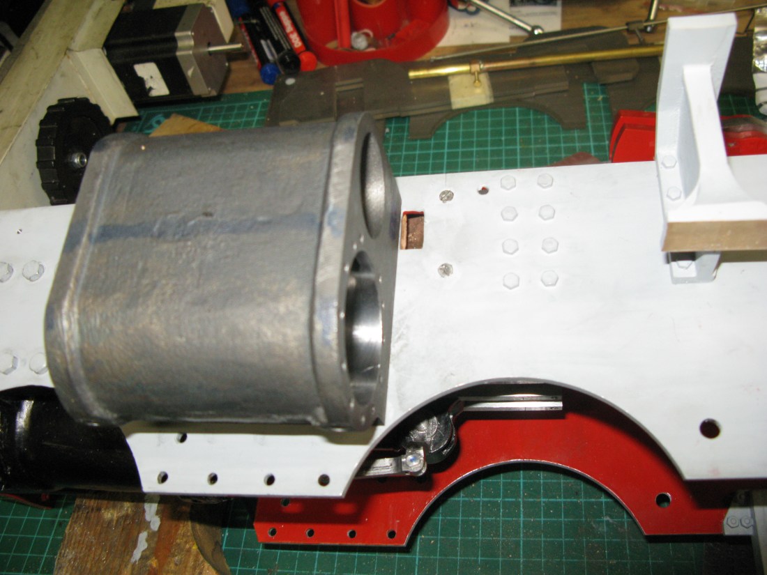
With all the valve rod components complete the time has come to fit the cylinder blocks to the frames. They are bolted to the frame using Loctite gasket material andthis was put on the cylinder block as seen below.

The seal wround the exhaust is all that is required but I put it all round the edges so the block would tighten up evenly onto the frame.
The 2 BA fixings were small head versions and these were all shortened to fit the depth of holes into which they fitted, the bottom row as seen in the picture have shallower holes than the top row.
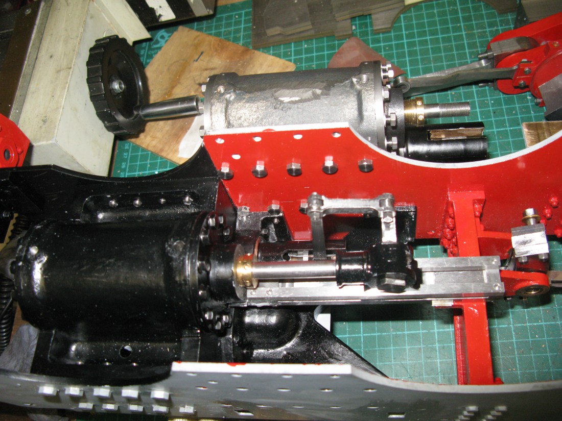
When fitting the cylinder block I found the screw in the bottom left hand corner fouled the K exhaust and cylinder block so I machined the head down to a 4 BA size and then found that a spanner would not be able to turn the set screw. To overcome this little problem I drilled two 5/64″ through the head on adjacent flats, one can just be seen in the photo, this allowed me to use a 5/64″ rod bent at a 30 Degree angle at the end to tighten the screw sufficently well.

One cylinder block fitted

All cylinder blocks fitted.
At this stage the piston rod end covers are still not bolted up as they have to come off when fitting the slide bar assembly.
Well after a year I can go back and close up the front valve chests having had a run on air.
The front valve chest covers are machined from cast iron and have an extension to accomodate the valve spindle and acts as a bearing surface for it.

Here are two of the covers which have yet to be drilled for the fixing screws.
Nothing special in making these other than to get a sliding fit into the valve chest. There is little pressure on the covers as they are on the exhaust steam exit path.

The fitted covers are shown above. Sharp eyed readers will notice a missing screw in the centre cylinder. That is because I managed to shear off the screw head whilst tightening it up. Access to the middle cylinder is cramped due to the lifting frame being immediately in front so I was using a ratchet driver at 90 degrees and of course the amount of force that can beapplied by the right angled handle is quite high especially on 8 BA screws! So later on that will have to be drilled out and retapped.
