I thought I would have a go at the inside motion or at least part of it at this stage (February 2018) as it would fit my overall plan of doing as much of the inside frame work as possible first.
Trunnion brackets
The trunnion brackets were my first job. These carry the expansion link. They are a pair of gun metal castings. Having in mind that these two brackets have to align squarely and at the right height on the motion plate as they determin one of the many fulcrums in the walshearts gear, machining them meant some careful set ups were going to be needed to ensure both were exactly the same.
The first task was to determin the approximate centre lines of the expansion link pins on the bracket. I say approximate as finally the centre will be determined from the base after it has been machined flat. Having determined the approximate centre lines the casting was clamped in the machine vice on the mill and the base rough machined flat.
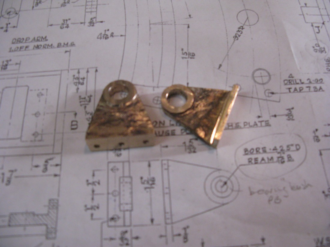
The casting was then turned on its edges in the vice so the upper side of the base could be machined parallel. With these two parallel faces the required distance from the centre line for the base could be determined and the base machine accordingly. Both castings were done to this stage. The photo below shows them at this point.

At this point I came across a problem. The amount of material on the base casting was insufficient to bring the centre point of the expansion link trunnion within a reasonable distance so the casting boss was central around it. It would have made a little difference if I had not cleaned up the top face of the base. A rethink was needed.
Clearly the base had to be thickened on its top so more could be machined off the bottom so I decided to silver solder a 1/16″ brass strip to the top. Having done this I decided the right thing to do was to machine the holes for the expansion link trunnions first and from these determin the base dimension, the opposite to how I set out to do it first time.
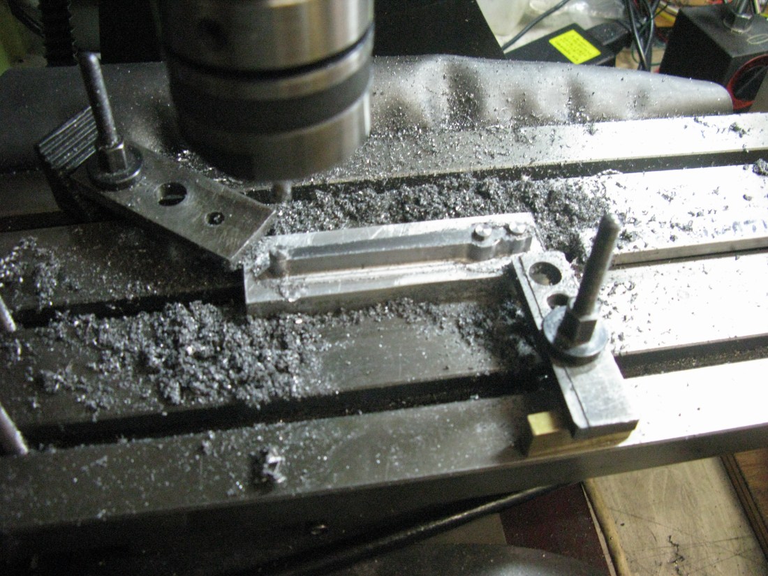
As I had a flat base the casting could be clamped in the vaice on the mill and a pilot hole drilled on the centre lines of the boss, opened out with a 1/4″ drill then a 29/64″ drill and finally reamed 7/16″.
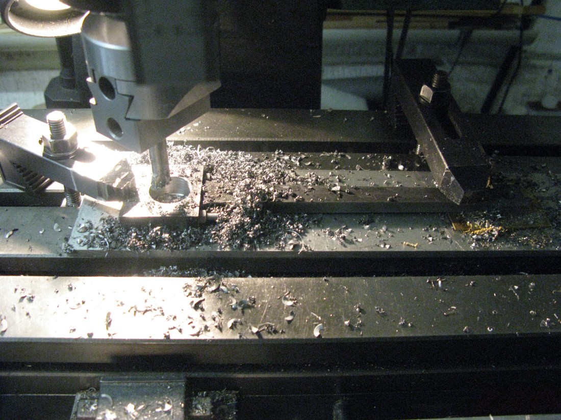
With both castings drilled and reamed a 7/16″ bar was put through the holes and the casting clamped in the mill vice so the base could machined and the fixing holes drilled. The bar enabled the casting to be set square in the vice as its horizontal position could be checked and it X axis was aligned with the x axis of the mill table. The Y axis being truly horizontal was less important as the base was going to be machined level anyway. This set up would ensure when the brackets were bolted to the motion plate the holes would align squarely and at the right centres.

The three fixing holes were first drilled in both castings ensuring the centre hole was over the centre of the trunnion hole and then the base milled down to the required 1 5/32″ from the centre line of the expansion link trunnion hole.

The last machining was to reduce the thickness of the base to 1/8″ and the boss down to 1/4″ thick and set 1/32″ above the inner face.
The trunnion brackets are now almost complete only requiring the PB bushes to be made and inserted and then a final clean up to remove the remaining scale from the heating of silver soldering.
Expansion link
The expansion link is an assembly of four plates, two either side of the die block and radius rod arrangement. (Oh no its not!! …..see later on for an explanation …so disregard what follows as its a big blooper!! ) The two inner plate form the expansion link in which the die block moves and are made form gauge plate and then case hardened. The two outer plate encompass the inner plates so the die block cannot fall out and carry the trunnions upon which the expansion link swivels.
I tackled the gauge plate plates first. I was going to use my CNC micro mill to machine them so the first job was to draw them out using CAD/CAM software and produce the required code for the CNC mill. In doing this I decided to place 3/32″ holes in the corners of the internal slot to allow the die block to travel the full extent of the slot as there would be no round corners. Of course round corners could be filed square but it made easier machining with a 3/32″ slot cutter as it would produce the squared ends as the cutter overlapped the holes.This done and the material set up on a sacraficial base the first plate was machined. It takes about 2 hours or so for the machining exercise as the feed rate for the cutter should really not be faster than an 1″/min and a cut depth of only 0.010″ was used to be less stressful on the cutter.
With the part complete and off the machine the finished reult was….well…. a disaster. There were regular small cyclic oscillations in the finished edges, not what was wanted for a sliding die block to move over. A sleep and some head scratching as to why this had occured left me non the wiser. Was it the machine, the drawing or something else? Having checked the CAM contours I was satisfied they were OK. The tool was still sharp and the end of the job so my attention turned to the mill. I first checked the software and the backlash compensation settings they seemed OK maybe a thou or so adjustment but nothing to cause the ripples experienced I then by chance tried the tables for twist and low and behold there was a slight movement which turnmed out to be an ill fitting gib towards one end of the Y travel. this was adjusted to remove the twist and I machined another plate. Success!
(The corrected version)!!
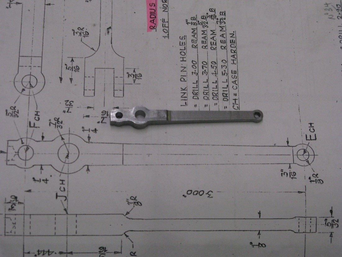
Apart from the bit about correcting the poor machining the above turns out to be wrong. Why? Well I had interpreted the drawing as an assembly of four plates which is incorrect. The reason for coming to that conclusion was a) the drawing contained errors and b) I was not familiar with the way the expansion link and radius rod mated together. It was only when I started to look at the various rods to order materials that I realised that the radius rod could never fit the expansion link as drawn and I searched for photo’s of the A1 motion to see how thay mated and found some photo’s of the motion work.
The expansion link is in fact three plates an inner one which carries the die block then a gap either side for the split radius rod and then an outer plate each side. The reason why this was not clear on the drawing is because the packing pieces that form the gaps between the plates and the centre expansion link were not drawn correctly on the end elevation, this made it look as if there were four plates not three. So rather peed off having spent time making two expansion links in 3/32″ gauge plate when it should be one off out of 1/4″ gauge plate.
So back almost to the begining, not quite as the two outer plates are OK.

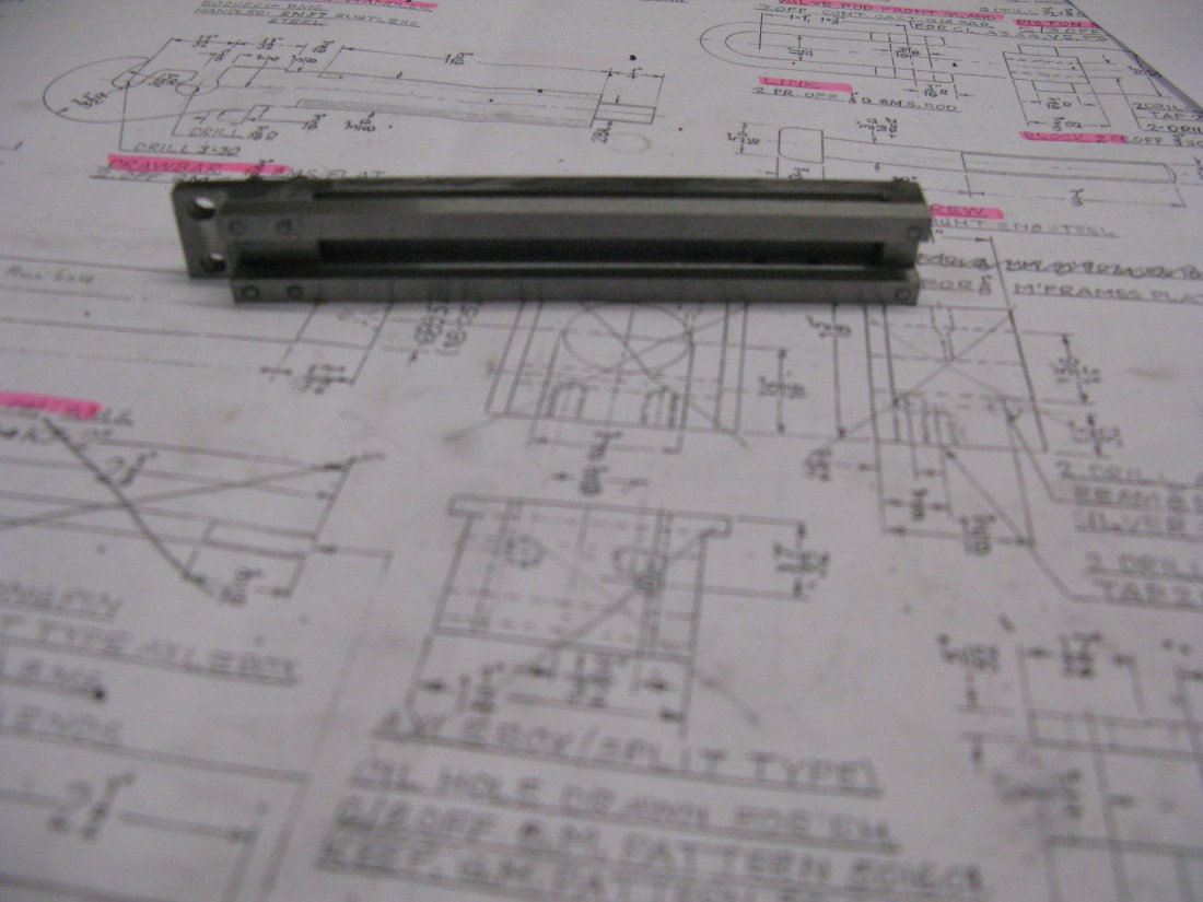
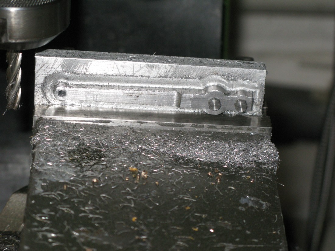
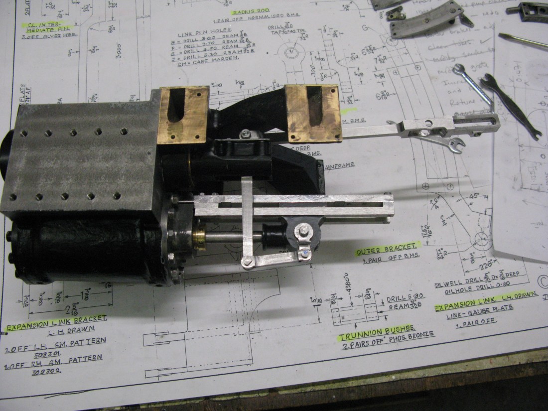
The completed outer plates, also how the drawing has been highlighted to reveal three plates not four with a 1/4″ gap between as I had originally assumed.

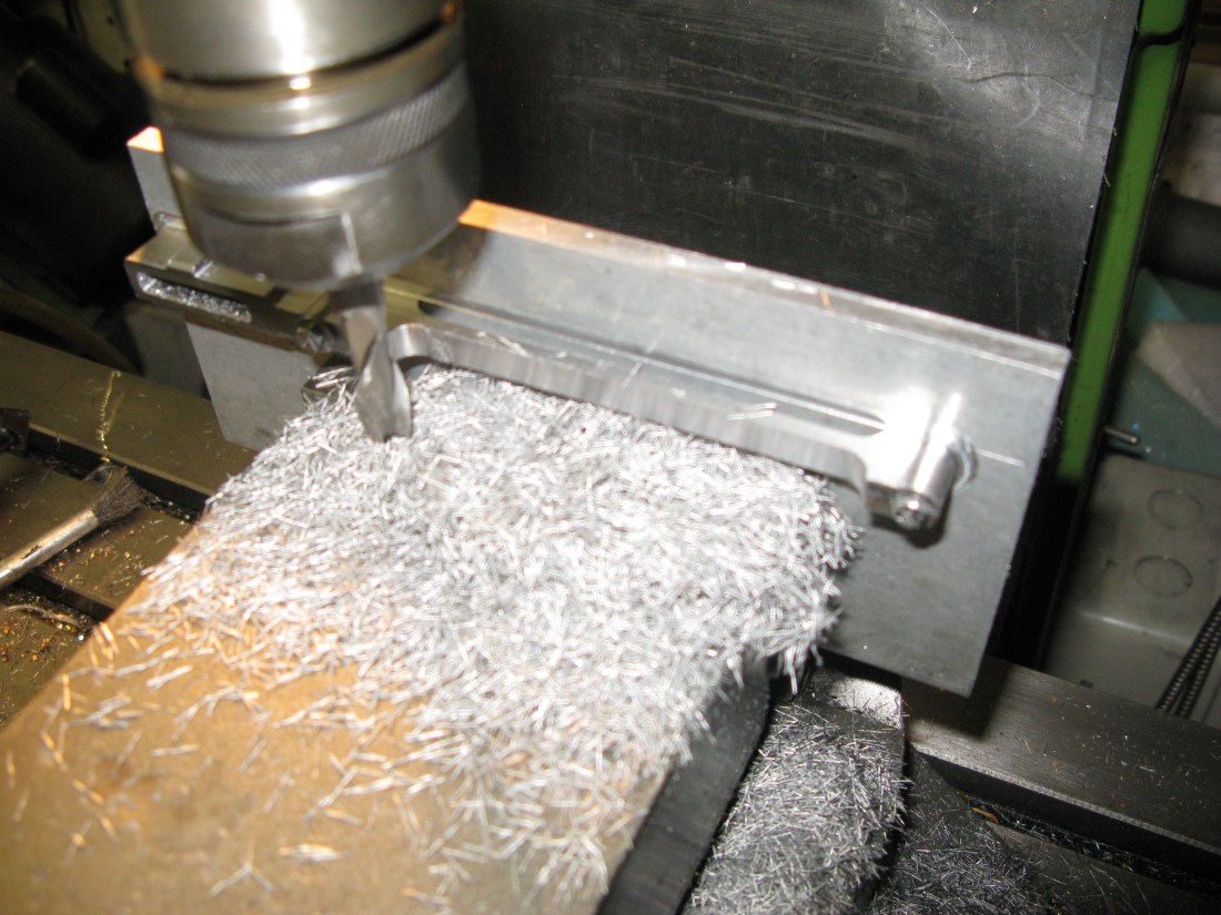
CNC machining the expansion link
I have given up trying to machine the expansion link without tools breaking. I have a suspicion its the material that is giving me problems with hard spots. It’s only a guess as swarf could also cause the problem but with plenty of oil and continuously cleaning out the slot the swarf is very fine and I am not inclined to think it is top of the list of probabilities. Anyway I gave up when the last tool broke half way through doing the external contour. Cut the link out with the band saw and then filed every thing. Now it needs a little tinkering to get the slot exactly the same width over its full length (and square) which means taking about 8thou off one end.
After a lot of hand finishing on the expansion link and making the dieblock from silver steel (on the CNC mill) more hand work to fit the die block to the expansion link. Why did it not fit if it was producd on a CNC machine? …..well because of the measurements taken of the slot with a vernier I was not confident of getting the size exactly right so I machined a few thou oversize.
Having acheived the block sliding up and down the link both needed to be hardened which was done in the oven, 800 degrees for 20 minutes following a preheat at 500 degrees for 20 minutes, then quenched in water. Followed straight away with tempering at 250 degrees for 15 minutes and natural cooling.
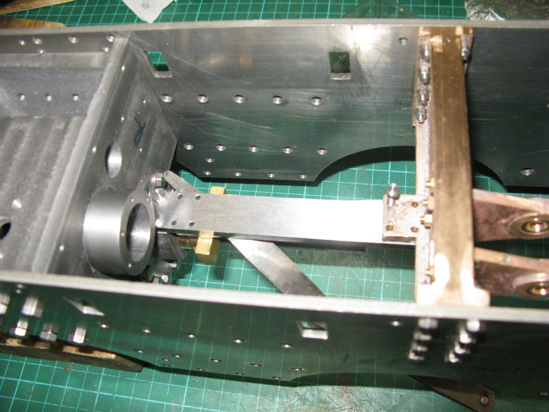
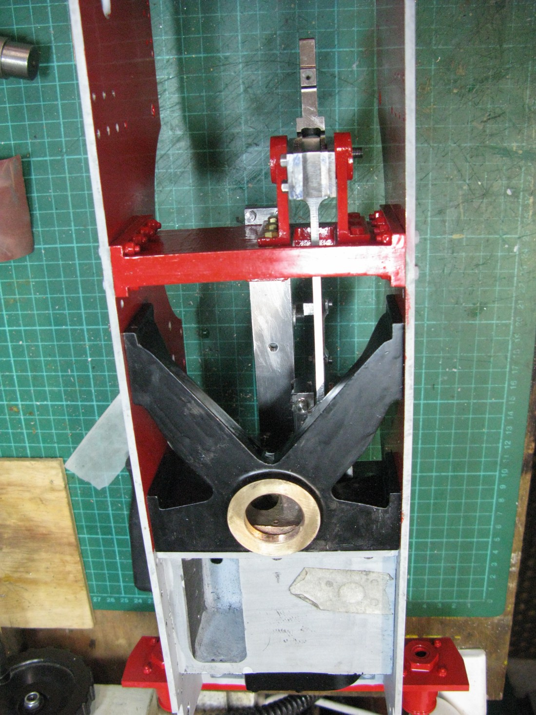
The assmbled expansion link in position
With the expamsion link all assembled it was trial fitted to the motion plate trunnion brackets and all was well.
Piston
Whilst waiting for some replacement tooling for the expansion link I thought I would have a go at the piston. A gun metal bar is supplied for the three pistons, partial sawn through …not very straight I add, and that left one rather tight on material to get a completed piston out of it.
The piston rings are to be made from cast iron and they measure 1/8″ square and I did not feel confident that these would spring open enough to clear the piston diameter to fit into their grooves. Using a piece of wire bent into a circle to match the inner ring diameter and then sprung open so the wire would clear the piston outer diameter proved the point as the gap had to be well in excess of 1/2″ so a good chance of them snapping. As there are two of them per piston my thoughts turned towards making a split piston so the rings could be simply slid into place. However making a split piston with three parts meant each had to be perfectly symetrical so when all three were together a parallel piston resulted.
I decided to go down this route and modified the piston design so it consisted of three parts with the splits at one end of the piston ring groove. I also gave the two inner parts a recess and matching plug to ensure alignment. The three parts were then to be screwed onto the piston rod which is 5/16″ diameter and finish turned on the rod mounted in a collet to ensure concentricity.
The first task was to rough machine the blank and drill and tap the 5/16″ x 32 tpi hole. The blank was then screwed onto the piston rod that had previouisly been threaded in a collet on the lathe to ensure concentricity and the die opened up fully as the thread had to be a good fit to the piston blank.
The step for the piston ring was turned and a 3/4″ dia x 1/16″ recess turned for the next disc to fit into. Having done this the blank was removed from the rod and placed in the 3-jaw chuck and parted off to allow a finishing cut to be taken to get the width which was done the with parted off disc back on the piston rod and in the collet.
With the blank back in the 3-jaw chuck the second disc had the plug part rough machined down to match the first disc recess allowing for finishing cuts to be taken when screwed onto the piston rod. Likewise the step for the piston ring. The disc was then parted off and screwed reversed onto the piston rod with the fist disc in place. This allowed the plug and piston ring diameters to be machined to finish size. The disc was then taken off the rod, reversed and screwed back on to check the plug fitted into the recess and the discs mated OK.
The third disc could not be made from the piston blank as there was insufficient material so a second blank was used, drilled and tapped for the 5/16″ x 32 thread and rough turned to oveall diameter and parted off. This was then screwed onto the piston rod to complete the three parts of the piston.

Having checked that all three parts abutted squarely the first disc was loctited onto the rod with high temperature Loctite. Once cured the other two discs were screwed on and the whole piston turned to size to match the cylinder block less a couple of thou.
In order to lock the remaining discs onto the piston rod once the rings were in place I planned to loctite them and also put a grub screw through the threaded joint beteen rod and piston which was as per drawing. But this must wait the manufacture of the rings.
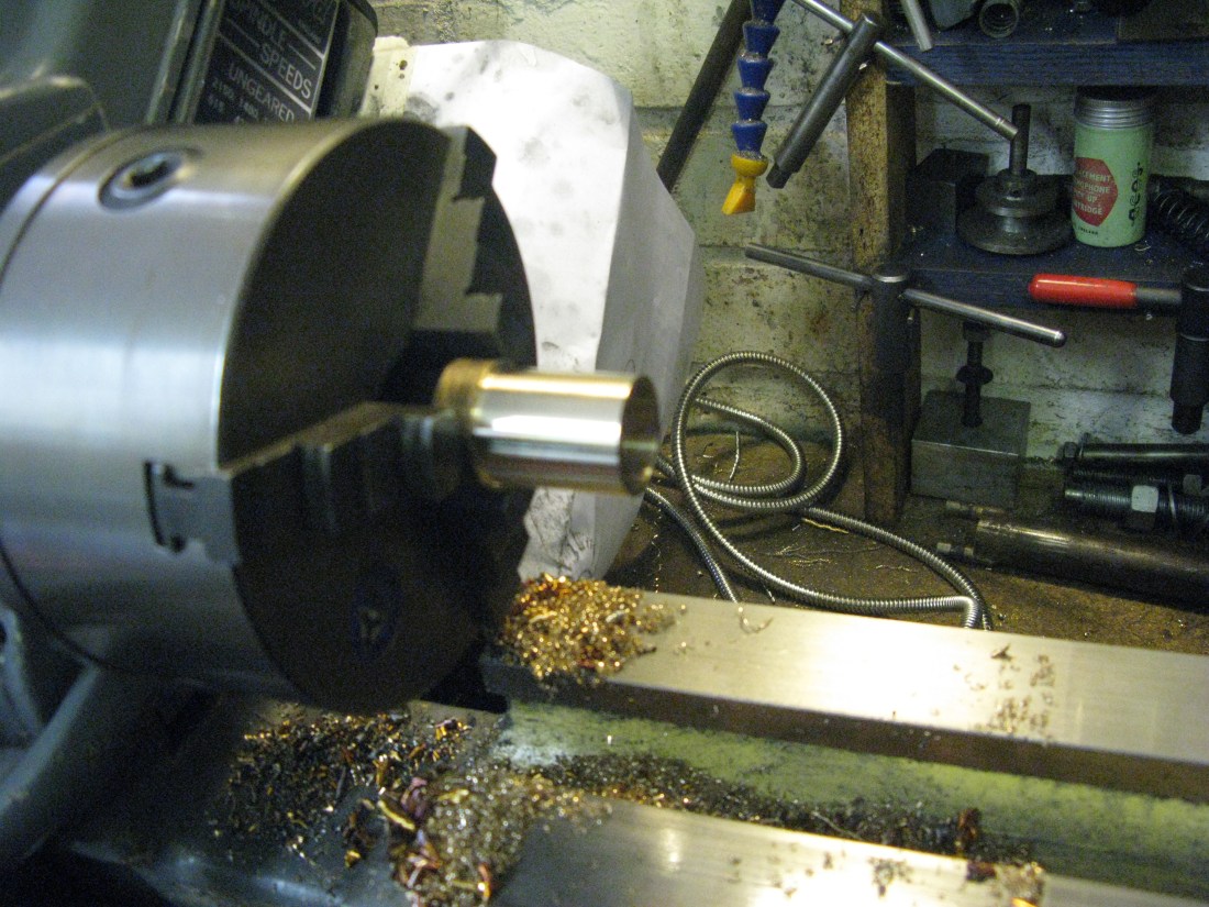
The completed piston less rings
Piston rings
The piston rings are cast iron. They are 1/8″ square in section and that makes them quite stiff which is the reason I built a split piston as there was no way the rings would spring open to clear the piston to get to their grooves.
Turning the rings was straight forward making them an exact fit to the cylinder bore and a slide fit onto the piston and a sliding fit in their groves. The next job was to split them. My practice is just to put them in the vice and with a pair of stout pliers as close to the vice jaws as possible bend the ring over and it just snaps. Of curse the snap is not a nice clean edge. Now depending upon who you read, the piston ring gap can be a small as a thou per inch of ring diameter to “it doesn’t really matter within reason”. The pundits provide lots of maths for ring pressure on the side walls etc. Me? I just go for a clean up with a small swiss file and the gap is what it is. The amount of leakage through the gap compared to the area of the piston is very small and has marginal impact on loss of power in my opinion. If you are a perfectionist then ignore my practice!
The rings can now be heat treated with a spacer in the gap to put a permanent set in the ring so that it exerts pressure on the cylinder walls. My practice again is to pop the rings into the oven ……. no not the wifes …..but my jewelry oven and heat to 600 degrees C soak for 15 minutes and then let them naturally cool. Again the size of the spacer is open to debate and there is much literature to calculate the size. My spacer was 0.115″. Bearing in mind there is already a gap in the ring from cleaning up the split the extra width of the spacer was not very much but sufficient to cause me a little concern that the ring might snap if I stressed it too much with the spacer.
An advantage of treatment at 600 degrees is that there is no scaling and no change to the molecular structure that can occur at cherry red temperatures.
Once cool, the rings are polished on fine emery paper all over and fitted to the piston and checked that they are free in their grooves and the piston is a nice sliding fit in its cylinder. Satisfied with that the piston has a 6 BA locking grub screw put into the end between rod and piston and everything assembled with a touch of high temperature loctite.
Slide bar
Why do the slide bar now? Well the cross head cannot be made without knowing the exact measurement between the slide bar and piston rod. Making it to the as drawn dimensions could well leave it too low and scrapped. Too high is not an option either as it has to slide in a 1/8″ slot made by the slide bars so too high would leave the underside with a gap not touching the slide bar and be scrapped also.
The slide bar is an assembly the top being 11/16″ by 3/16″ with two 3/16″ square sections underneath at the sides with spacers each end to form the slot in which the cross head slides. It is all made from gauge plate and hardened.
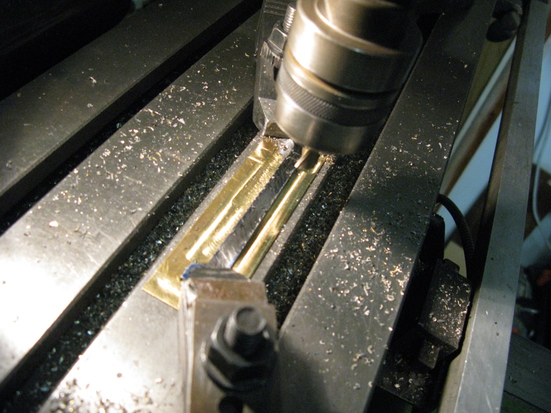
Slitting the gauge plate for the top slide bar
With top slide bar made it can be bolted to the cylinder cover and checked to see if it will fit to the motion plate and end up parallel with the piston rod. I did not expect mine to line up first time accurately and I was not disapointed! Even Tornado had its slide bars shimmed to get everything aligned correctly so why should I expect to be different?
Just as a check the angle of the cylinder block was measured compared to the frame using a digital protractor. The correct angle is 1 degree 9 minutes or 1 in 50 or 2%. Mine was around 1.9% to 2.01% as near as I could tell as the instrument does not seem to give a consistant stable reading. However it was good enough I thought and I could look to start checking if the bar was parallel with the piston rod. The bar was bolted to the cylinder cover but left loose at the motion plate end. Using a block and feeler gauges I established it was not parallel. With the piston fully pushed back the gap was wider than when the piston was fully extended by about 0.010″. This probably meant that the top surface of the cylinder cover to which the bar is bolted was not perfectly square and would need dressing. As an alternative measure I bolted the bar to the motion plate and left the cylinder cover end loose and this time using slip gauges I found that if the cylinder end was packed up by 0.006″ the bar was parallel with the piston rod. So this was the solution adopted.
Having obtained an accurate measurement between the piston road and slide bar I could think about the manuafcture of the cross head with some confidence it would fit.
To complete the slide bar 1/8″ packers are placed at each end of the bar and 3/16″ square gauge plate screwed on top either side to form a slot in the middle. To ensure the slot was parallel I used slip gauges and jewelers clamps to postion the bars for jig drilling from the top slide bar, the holes then being tapped 7 BA.
The assembled slide bar
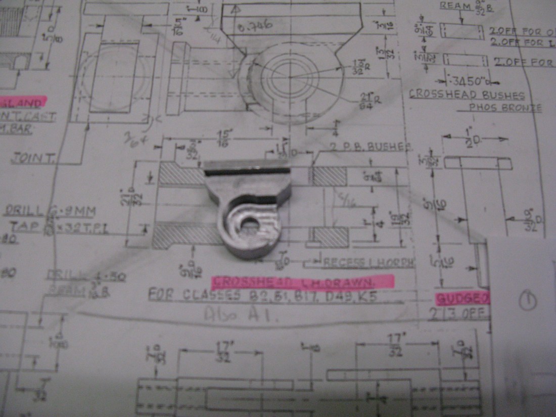
Cross head
This is, pardon the language, a pig to make. There is no casting available and the drawing is quite confusing at first glance. There is no drawn cross head for the A1. Other locomotives are named on the cross head drawn but not the A1. Then next to it is a part of the cross head with the drop link (for the outside cylinders) which is marked for the A1.
A bit of reasearch on full size seemed to suggest that the cross head drawn was OK for the A1 so that is what I went with.
I spent quite a bit of time trying to work out how to make the cross head as it consists of the round boss end that screws onto the piston rod then the shaped head itself with the recess in the middle to accept the connecting rod.

I opted to make it in three parts, the main body which includes the cavity, a plate outside to cover the cavity and the round boss end for screwing onto the piston rod. As can be seen from the drawing the round boss end cannot be fully turned if it were part of the body due to the overhang of the slide bar T arrangement. My marks on the drawing indicate the step for locating the boss in the body.
I started with a piece of 1 1/4″ square MS bar 3/4″ wide from which to machine the body. A flat surface was first milled on one side and then the block turned over and clamped to the mill bed to machine a 3/16″ deep face that will eventually accept the flat plate to be silver soldered to it.
This had to be machined in two steps as the clamp had to be moved to get the whole surface done. I did try clamping the block to the fence but could not get it secure enough and stop it rising up under the cutter.
Once this was done I used my little X1 CNC mill to machine the cavity for the liitle end of the connectimg rod.

The block then needed to be set up again on the mill table such that the center hole through which it was bolted to the table was accuratly located as the top sliding face had to be the correct dimension from the center line.
Then the outside contour was then milled having bolted the block down really securely through its central hole.
After a final clean up of any burrs the finished block looked like this:
The 9/64 thick plate to close the cavity was made next, another CNC profiled task using the same clamping arrangement as before having machined a piece of bar to the required thickness.
Finally the boss part was turned and drilled/threaded 5/16″ x 32 with the end given a curved profile to match the inside of the cavity.
The three pieces looked like this:
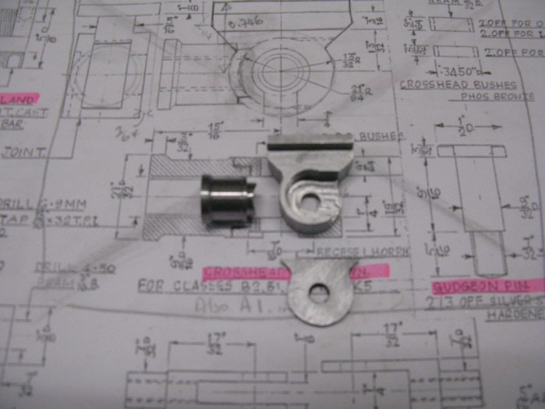
The main body and cover plate will be silver soldered together first. Then they will be machined to accept the boss which will in turn be silver soldered in place with the body suitable clamped to ensure the cover plate does not move whilst doing so. Finally The other side of the cross head has to be machined down to size and create the slot for the slide bar and the central hole machined to accept the PB bushes for the gudgeon pin. Because of the curvature of the body there will be a small gap top and bottom where the boss meets the body after soldering and this will be filled with epoxy metal filler. The cover plate also has to have a slot and circular recess to accept the drop link which is held in place by a nut on the end of the gudgeon pin.
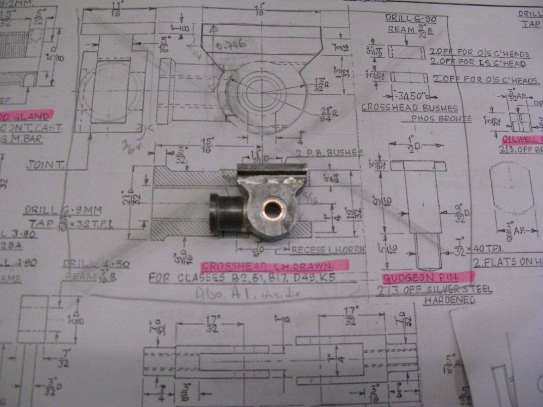
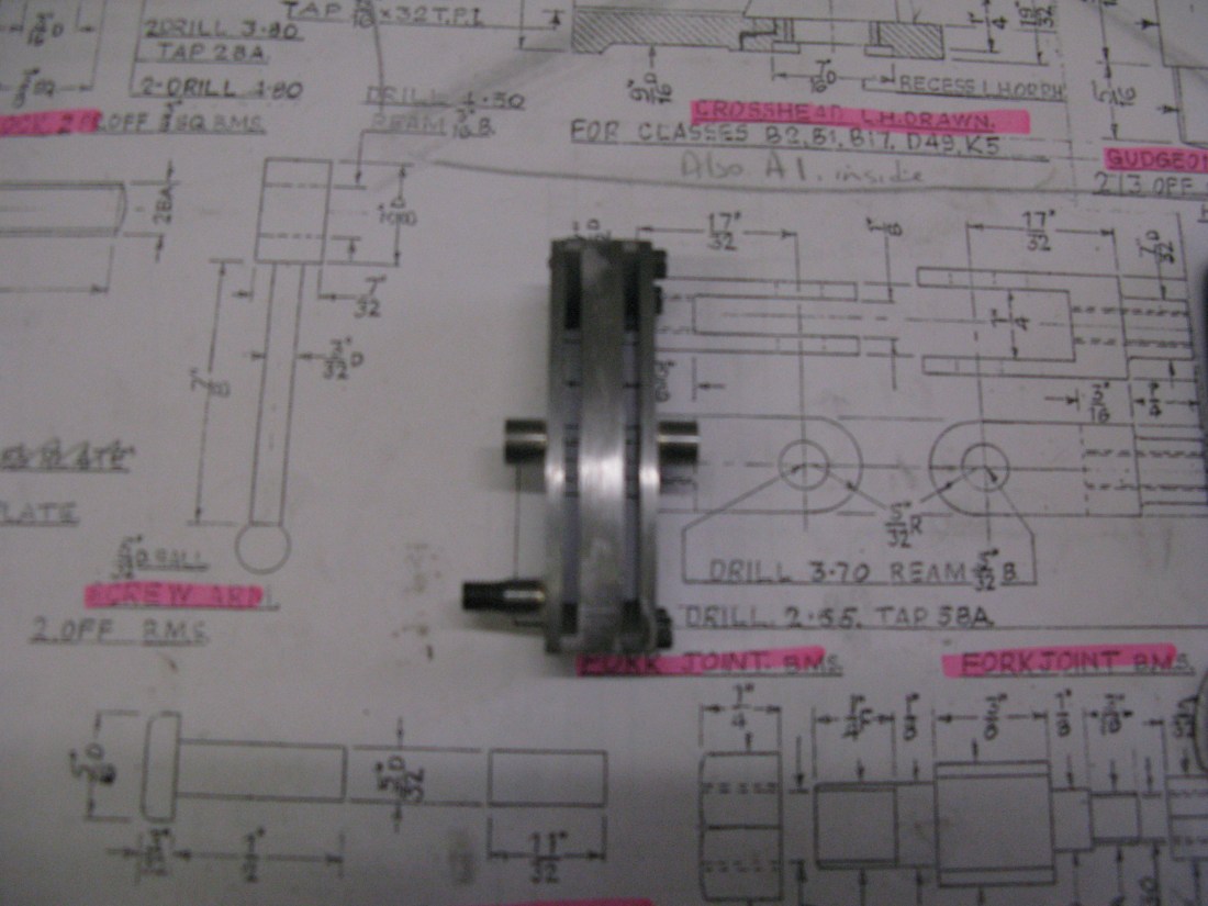
The completed crosshead
The final check was to see that the cross head would fit and slide up and down the slide bars which was done.

And finally the whole was assembled in the frames, crosshead first screwed onto the piston then the top slide bar fitted with one of its under side bars fitted which allowed the whole to be maneuvered onto the crosshead followed by the 3/16″ square under slide bar on the other side and then the whole bolted loosley in place. This allowed the piston and crosshead to slide up and down OK. the slide bars were then tightened at the motion plate end and the piston end just nipped to check free movement still existed remembering that I had established a 0.006″ shim would be needed which was checked with a feeler gauge which turned out to be OK. So a couple of shims to make 0.006″ were cut and drilled, fitted and the slide bar tightened down and everything moved OK.
Eccentric arm
The arm to the ecentric needed to have set put in it as a result of my machining the strap on the wrong side to accept it. The reason why the strap cannot be simply reversed is because the oil holes would then be underneath rather than on top and oil will not run uphill!
The arm was to be made with its boss connecting to the expansion link silver soldered to the arm which enabled me to make the arm, put in the set and then machine it to the correct length to accept the boss and give the correct distance between boss and eccentric.
The arm is made from 3/32″ thick mild steel and its profile milled manually. The set was put in and checked “on the job” and adjusted as required to get the arm to sit squarely on both the strap and against the expansion link.
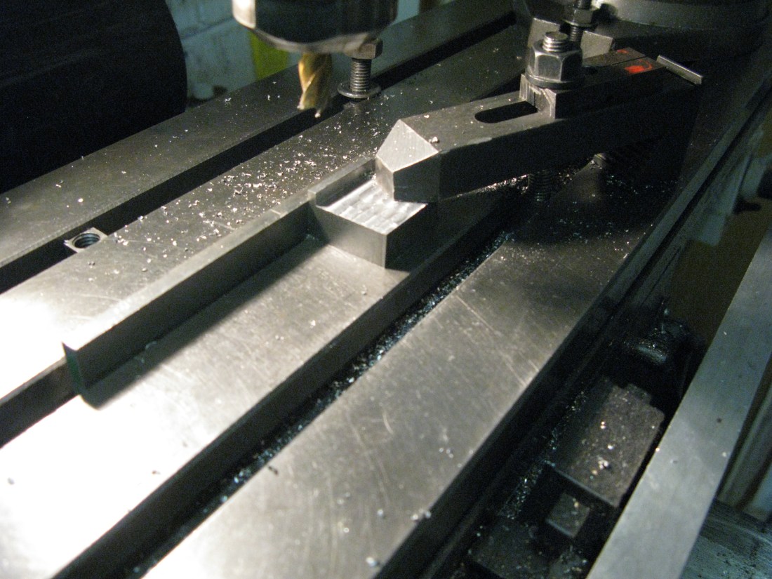
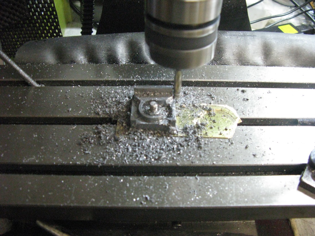
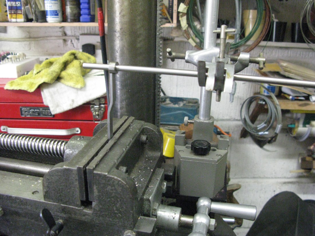
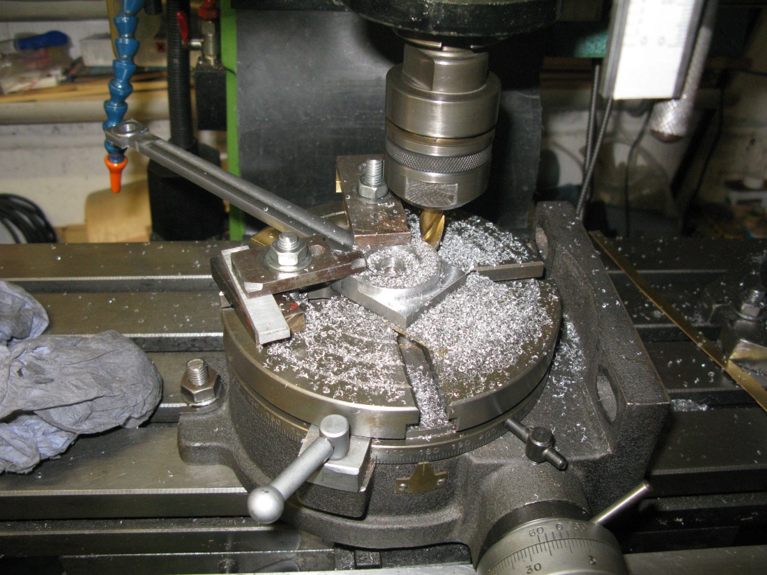
Machining the eccentric arm
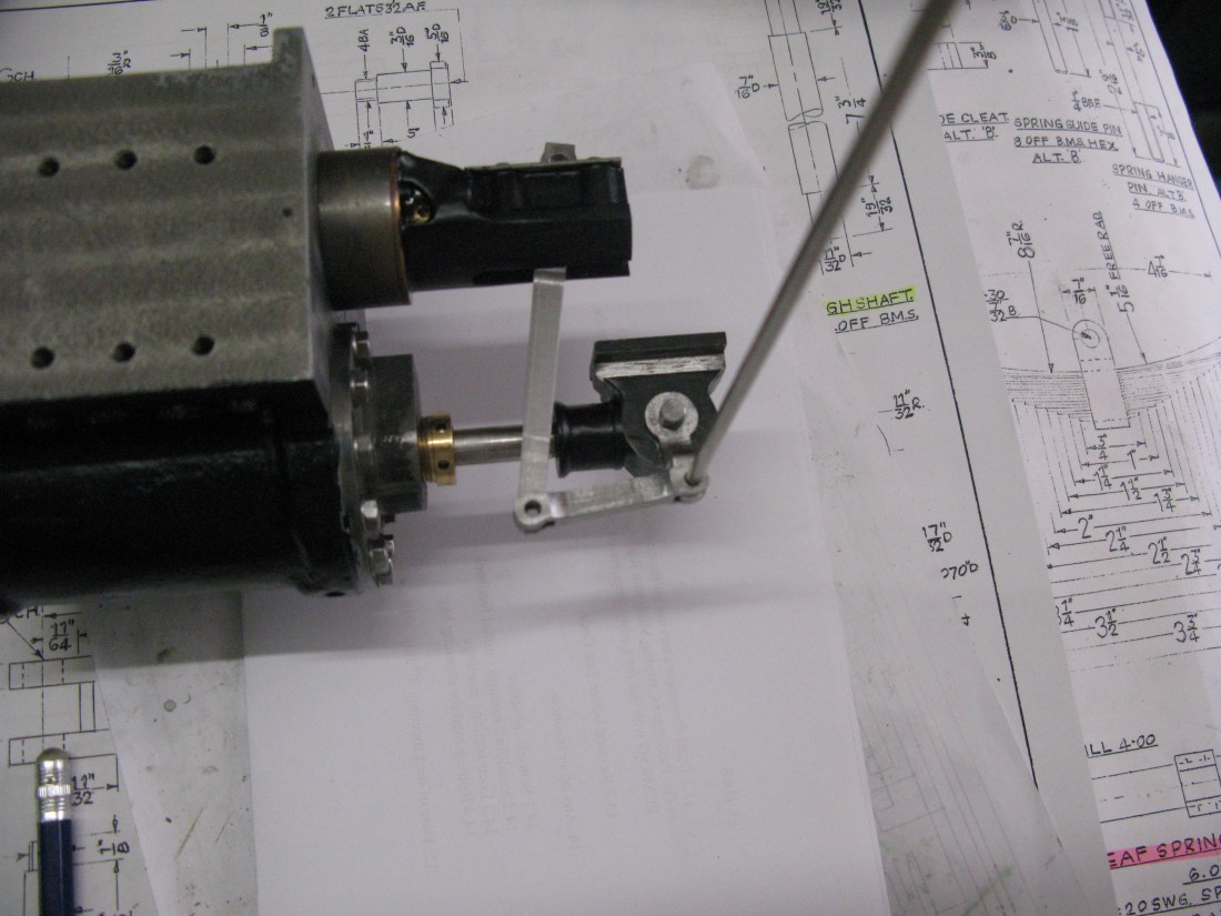
With this done the length of the arm was machined to the as drawn dimension between strap and expansion link pin. The boss turned and then silver soldered in position. To ensure the boss was soldered squarely the set up shown in the photo was used.
The arm is fixed to the strap with two 5 BA HH set screws and nuts. The heads need thinning down to clear the horn block which is shown on the drawing.
The fixing at the expansion link requires a 3/16″ x 40 ME thread nut which was made and fitted with a brass washer to act as a thrust plate rather than have the boss rub against the nut.
Eccentric arm in place
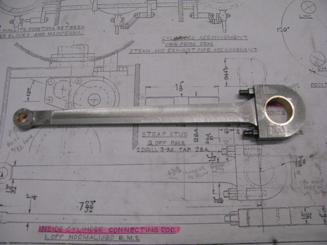
Connecting rod
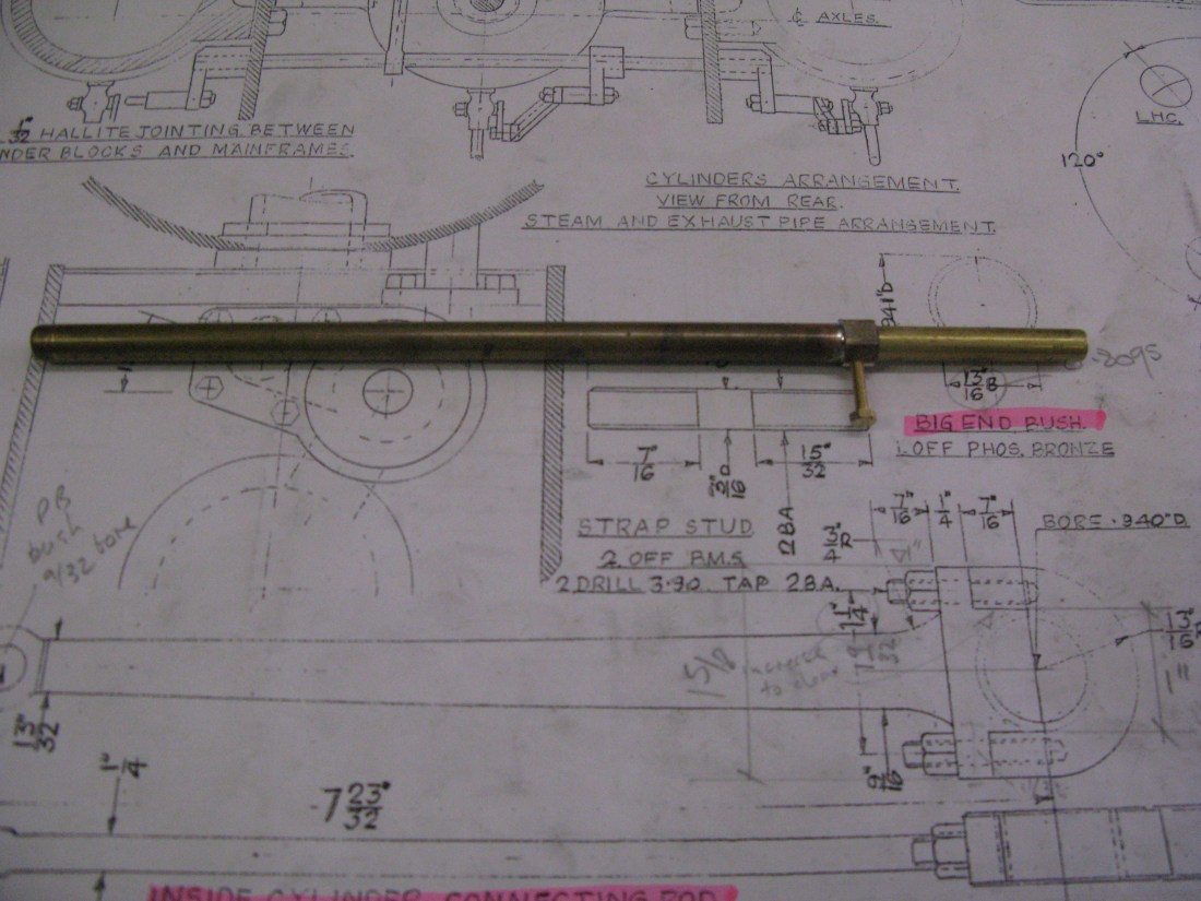
The connecting rod is made from 1/2″ by 1 3/4″ bar. Knowing how rolled bar can move and twist when machined as a result of stresses being released the plan was to rough machine it and then stress relieve in the oven before final machining.
The connecting rod has a split big end and as drawn the big end bush OD produces a razor edge to the mild steel rod at the split point. I was not comfortable with that design and chose to widen the rod at the split point to remove the razor edge. This would also mean slightly widening the centres of the fixing studs to ensure clearance for the studs.

Initial rough machined to thickness of little end boss before normalising
The connecting rod having been rough machined down to the thickness of the little end it was normalised in the oven by soaking at 500 degrees for half an hour then raising to 900 degrees for half an hour and left to cool naturally in the oven with the door ajar.
Whilst the connecting rod was normalising the big end strap had its recess machined ready to use when machining the connecting rod matching end.
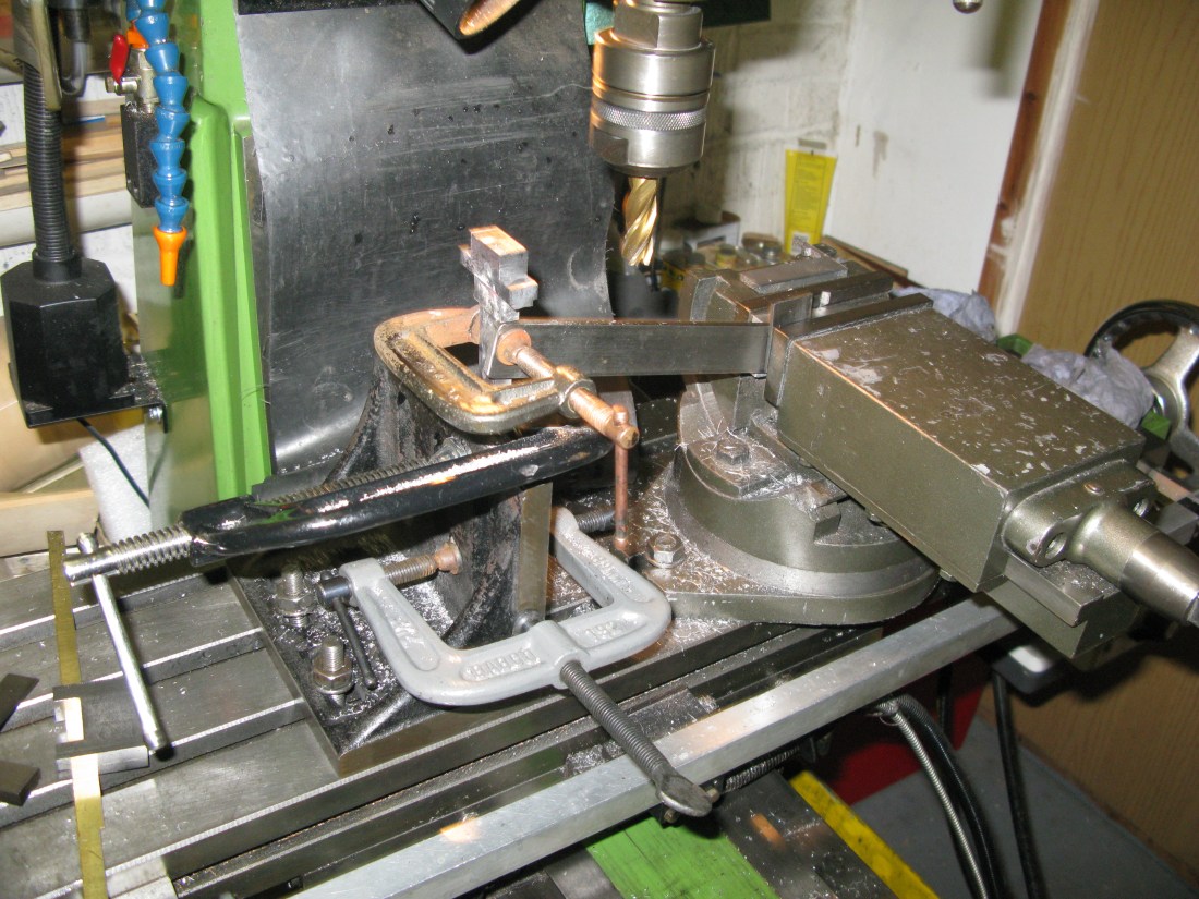
With the connecting rod bar cooled off it was marked out and rough machined to its width (i.e. top to bottom) and then, changing the set up, its strap end machined to mate with the strap using the rather Heath Robinson affair to hold the work solid. (a horizontal mill would be useful for this task ……… called a lathe with a vertical slide, but I did not think of this until too late).
With the strap and rod now fitting together the next job was the make the studs, drill and tap the strap and drill the rod so it could all be bolted together.

Before I went further I decide to check the dimension for the rod length and to do this I made up a simple gauging rod from two pieces of brass tube that fit inside each other and which could be slid between the crank pin and the cross head pin.
As far as I could tell with this device the as drawn dimension was OK.
With this knowledge the connecting rod could have its big end bored and the little end drilled and finished machined to the correct size.

The complete rod was set up on the rotary table to machine the rounded end of the strap and also the little end machined in the same way. I use jig pieces to fit the bore of the work and fit into the No2 morse taper of the rotary table to ensure the work is centred.
Machining the rounded end of the strap
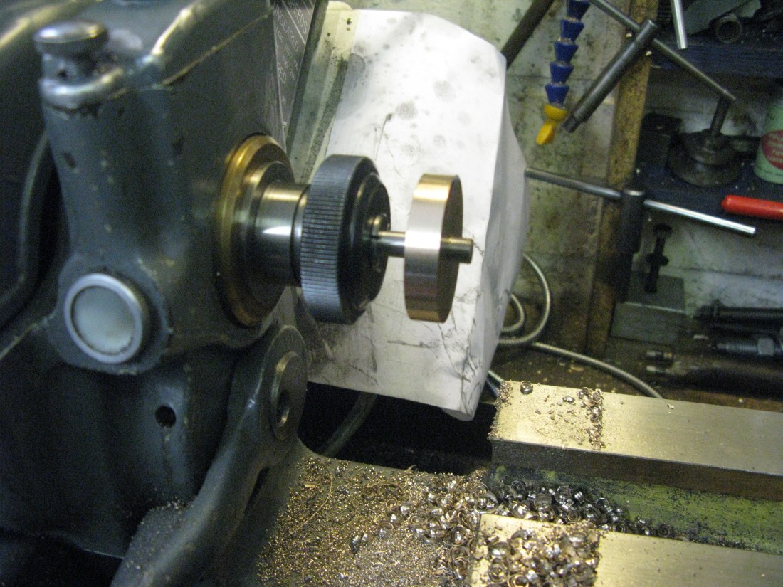
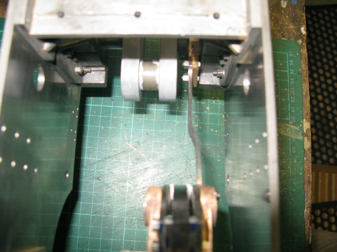
To make the split bearing from PB I chose to machine the bore and outside diameter first to twice the length plus (for the parting tool width) and then machine the cylinder produced to half height to produce one half of the bearing and then cut the joined halves so produced to give two halves. The two halves were then clamped in a self centering four jaw chuck to face them and then turned around to face them to the correct width to give a perfectly matched pair.
The PB big end bearing having been turned.
Checking the fit of the rod to the bearing shell
Finally the big end shells were fitted in place and the little end bush to complete the rod.
Test fitting of the big end and small end followed. Big end first which proved to be a little stiff. This turned out to be a combination of paint and too little clearance on the width. This was solved by removing 0.020 equally from both sides of the big end. The little end would not fit into the cross head due to the gap in the cross head being too small. This was resolved by machining 0.020″ off the diameter of the little end. With both minor mods done the connecting rod was assembled onto the cross head first, as this needs some fiddling to get the gudgeon pin to slide in and then onto the crank axle. Rotating the crank axle seemed to be a little stiff and then a solid stop. This was due to the piston coming up against the cylinder cover. This was resolved by moving the cross head back on the piston rod one turn. Sounds simple enough to write but involves a lot of dismantling and reassembly to do that. In performing these checks the crank axle bearings were jacked up by spacers to give the approximate running position.
The motion overall was still a little stiff and I put this down to the combining friction of the piston, cross head/slide bar assembly and finally the big end bearing. I concluded the stiffness was certainly not excessive and a final conclusion would be determined when the wheel set was fitted and some feel for the rolling resistance enabled.
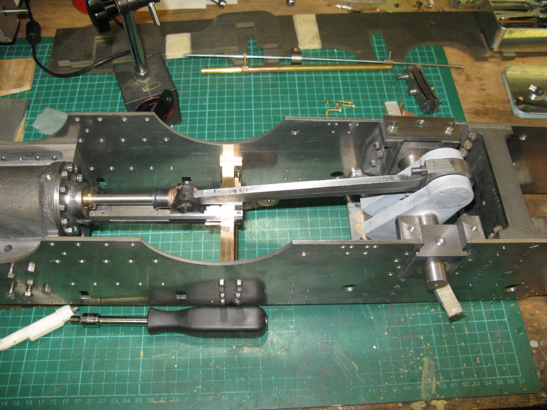
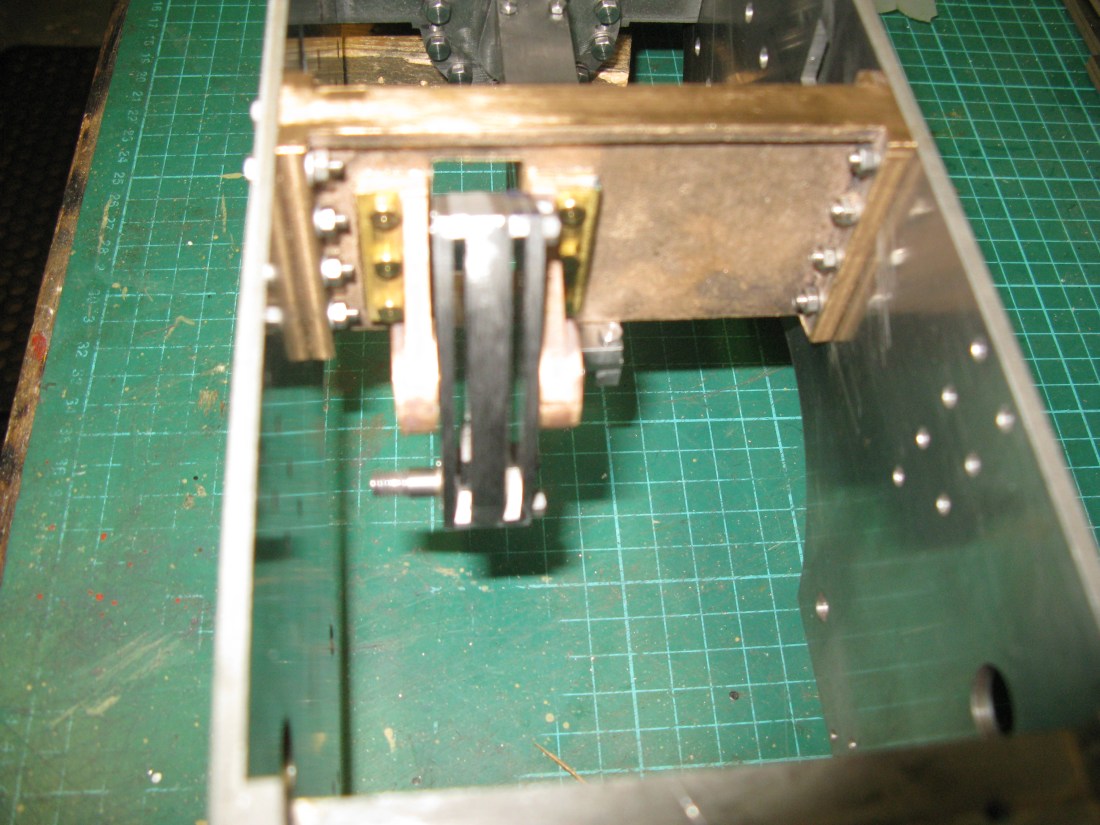
Connecting rod fitted
It occured to me whilst doing the above that there is no oiling provision for the big end so I must remember to put a gravity fed oil feed pipe above the big end bearing at a suitable position perhaps when it is at top dead centre and use one of the dummy oiler postions to feed the oil to it when stationary.
Piston Valve
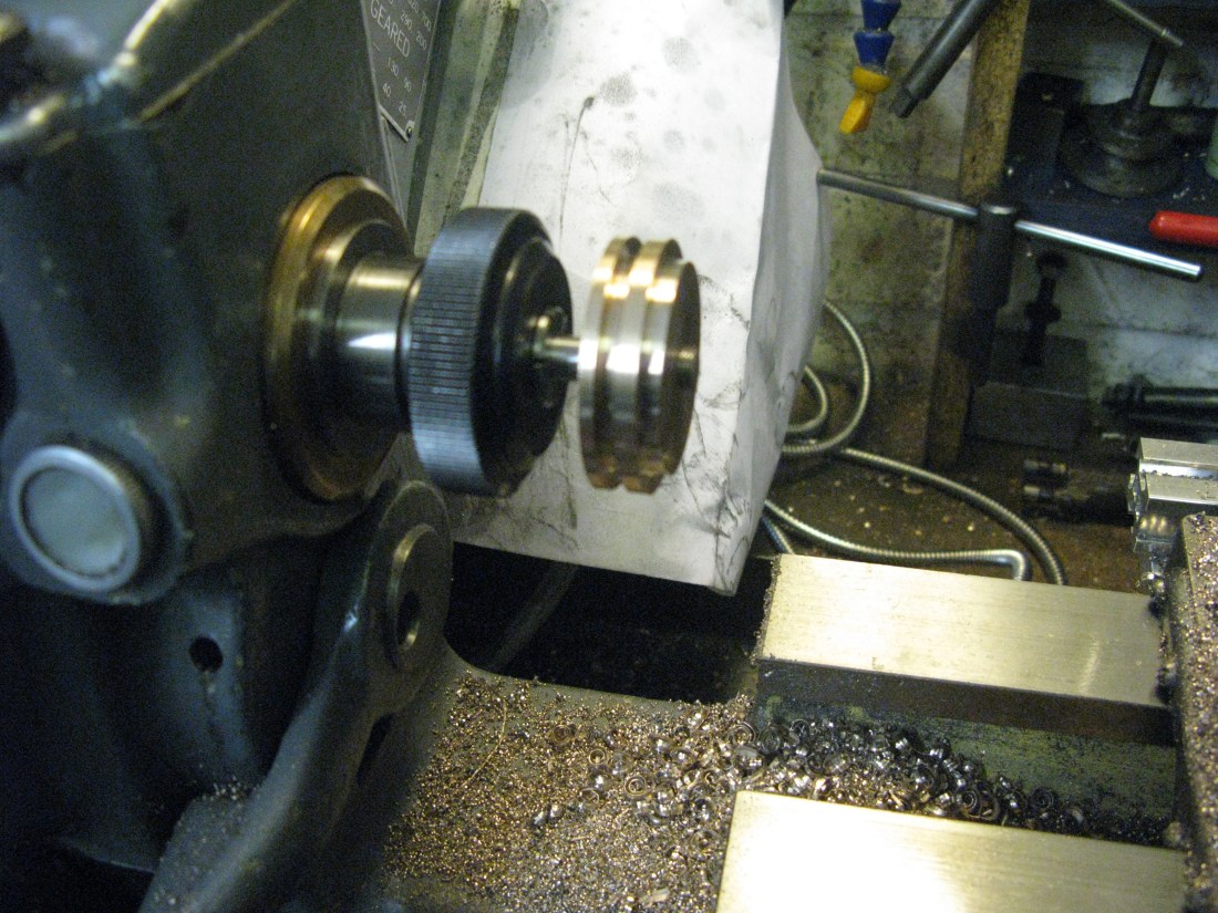
My next job, the piston valve. The bobbin is made from silver steel 1″ diameter and turned down to 7/8″ to fit the liners and waisted in the middle to 3/8″ diameter and having a 7/32″ hole through the middle for the valve rod. There are two cast iron rings at each end 1/16″ square.
Turning the bobbin is straight forward but takes quite a while. The tolerance between bore and bobbin diameter is not given but I reasoned 0.002″ – 0.005″ undersize should be adequate to ensure no seizure (poor old Tornado!). Turning the grooves for the piston rings was done with a parting tool ground to just over 1/16″ wide …what’s “just over”? no more than a couple of thou.
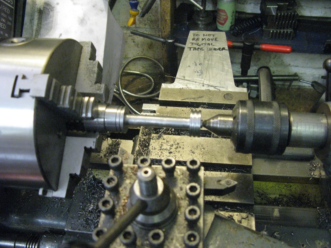
To bore the 7/32″ hole for the valve rod requires a long series drill but otherwise presents no problems as long as mutiple pecks are used to clear the swarf……….I spoke too soon. Having taken the work out of the chuck I find the hole has vered off centre. Trying to correct this problem is not easy as it can only be done by one of two ways …….. scrap the item and start again of bore out to a larger size, well not bore as its too small a hole for a boring bar and over 2 3/4″ in long it would not be strong enough anyway. So I resorted to a short 1/4″ slot cutter reasoning it would be stiff enough to not be thrown off centre by the cutting forces of the off centre rotating hole and then using a long series slot cutter and after that repeating the process from the other end and finally running a 1/4″ reamer through the hole. This seemed to give an acceptable result so I decided to make the valve rod from 1/4″ silver steel and turn the ends down to 7/32″ so the valve end caps etc were still as drawn. Only when the whole valve is assembled in the cylinder block will I know if this approach has been a success.
So onto the valve rod. Looking at the drawing it shows a 1/32″ shim between the bobbin and the collar on the rod against which the bobbin is locked solid. Why? The collar could be moved to be 1/32″ further forward or even made 1/32″ wider. I could not see it was there for a fine adjustment of the bobbin position relative to the valve ports as this can be achieved by turning the cross head further on or off the rod. Puzzled, I decided to leave the shim out and make the collar wider. At least if I have missed the point of the shim I can always turn the collar back to size.
As I did not have the 1/4″ silver steel for the valve rod and I could get some at the model show in Doncaster in a few days time I decided to have a go at the valve rod crosshead guide in the meantime. Not an easy casting to deal with. It is the end cap for the cylinder and the guide has a lot of material cut away which makes it reliant upon a small amount to provide the sliding surfaces for the crosshead and there is little rigidity as a consequence. The drawing has a few dimensions missing but they could be established by scaling off the drawing.
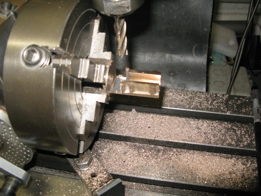
I used the four jaw chuck to hold the “arms” forming the sliding surfaces so the cap end could be turned and the valve rod hole drilled. This was straight forward. The work was then turned around in the chuck and using the dti made to run true. The outer edges of the “arms” could now be turned to clean up and the length bought to size by facing off.
The chuck was then removed from the lathe and mounted on the dividing head on the mill and the work set up so the “arms” were vertical. The top surface of the “arms were then machined down to size. Next the slot that takes the combination lever was cleaned up and then the gap between the end cap and sliding surfaces machined out.
The 7BA holes to hold the gauge plate top slide plates were drilled and the work needed to be supported due to the bending moment applied by the drilling.
The next task was to drill the end cap to be tapped for the gland bush. The dividing head was turned to vertical and a letter Y drill used to drill the tapping hole for 7/16 x 32 ME. This was not successful as the resulting hole was not truly central so it could not be used to tap the thread as the gland bush would be off centre. Why the drill wandered is a mystery. So the chuck was put back on the lathe and the hole bored to be true. The plan to rectify this problem is to make a bush already threaded that can be silver soldered into the bored out hole.

So, the bush was made but threaded 3/8″ x 40 tpi rather than 7/16″ x 32 tpi. The reason for the smaller size was to fit the size of the bored out hole diameter which was restricted by the tool bar coming up against the “arms” and to verify the bush was in square by checking that a 3/8″ x 40 tpi tap would screw in in cleanly. (A 7/16″ tap would just foul in the “arms”). Using a 40 tpi thread rather than a 32 tpi gave a few more threads in the bush which was only 0.178″ deep. The bush fitted the hole OK and it was silver soldered in place.
The holes in the arms were tapped 7 BA to hold the top of the cross head slide which is made from 1/32″ gauge plate.

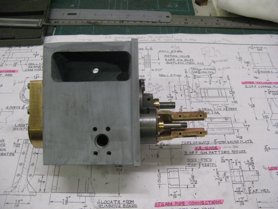
The cross head guide fitted to the cylinder block. Note the gap between cap and sliding surfaces. The drawing upper right shows why it is there.
The more I looked at the cross head guide the more dissatisfied I became with the fact that the drawing had shown a big slice of the casting milled away creating the slot between the end cap and sliding surface. It made the arms potentially weak. Looking at the full size it was not made like this and also looking at other A1 pictures of models they did not have it either. I decided to put back in the web that was removed as best I could using 1/8″ brass with a cut out to enable the fixing bolts to be put in place. The new web pieces were silver soldered in place and now the arms are well supported.

The replaced web either side to restore the strength to the arms. (Uncleaned up). An overnight soak in citric acid will produce a clean valve guide
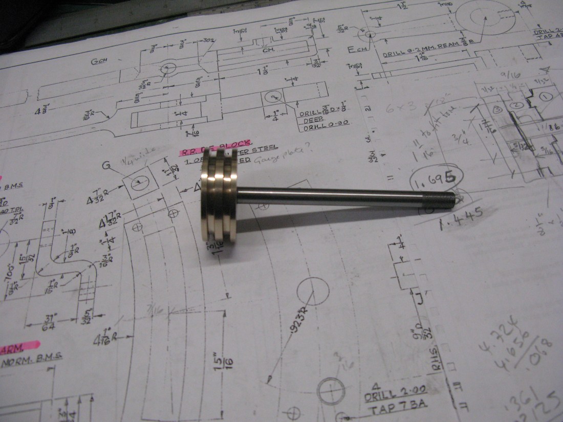
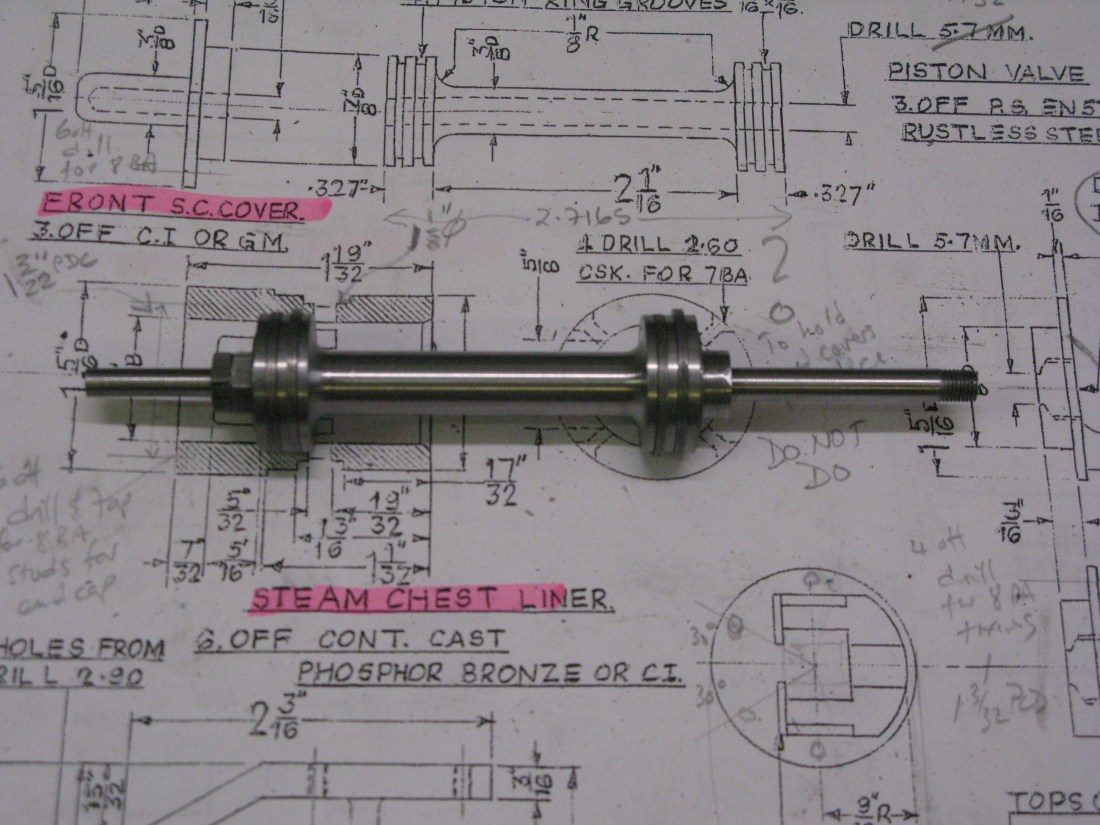
Having procured the 1/4″ silver steel for the piston valve rod it could be turned to the required dimensions at each of its ends and threaded as per drawing. The turning was done using a 1/4″ collet to ensure the rod ran true. The end at the front of the bobbin has a 10 thou flat to ensure there is no hydraulic ram effect as it slides in the front end cap. I also put a slot in this end for a scewdriver as the rod needs to be turned to screw the valve rod crosshead onto the rod whilst in the crosshead guide.
With the rod and bobbin mated together the next job was its piston rings. These are cast iron and are 1/16″ x 1/16″ in cross section. The outside diameter of the cast iron bar was turned down to be exactly 7/8″ being the bore size. It was then drilled and bored out to be 3/4″ +0.005/-0.0 to ensure the rings were free on the bobbin when inside the bore of the valve. The rings were gapped with spacers and heat treated the same way as the main piston rings were done.

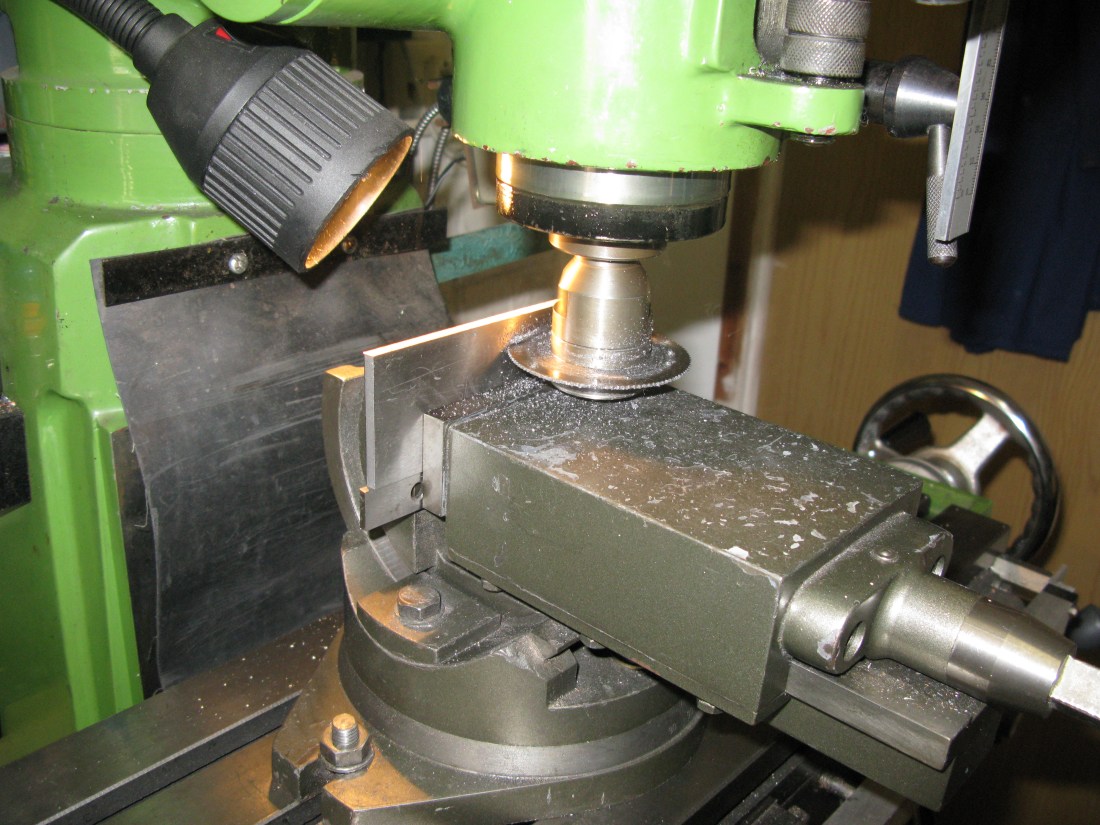
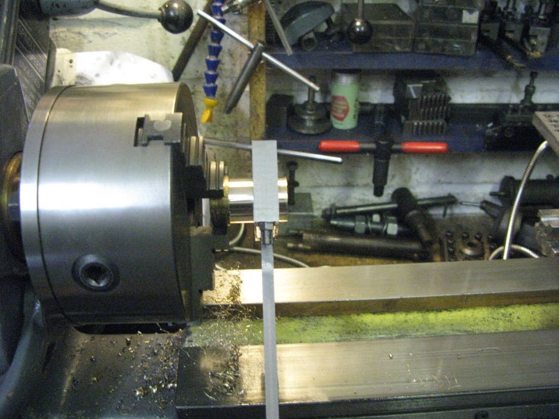
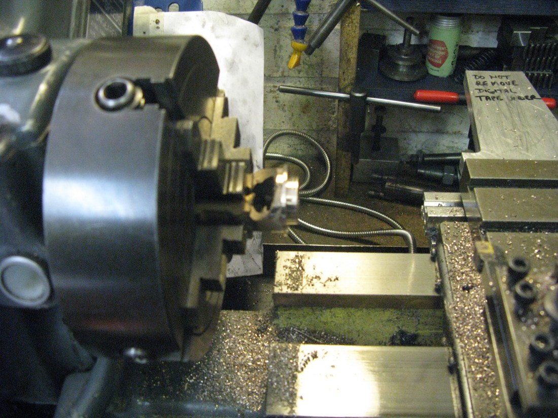
Machining the piston rings – parting off
A set back then occured. There is no way the rings are going to go over the bobbin without breaking, they are just too stiff to spring over the bobbin diameter.
The only solution was to modify the bobbin to have split ends, the same as the main piston, so the rings can just be slid into place. The split ends could be held in place by the collar on the rod at one end the the fixing and lock nuts on the rod at the other end with perhaps a 1/32″ x 1/2″ wide washer to spread the load. Although the split parts will have a reamed 1/4″ hole to fit the rod there is still the possibilty that the tolerances will not provide alignment of the bobbin parts exactly. However once installed in the liners and the bobbin locking nuts fully tightened no misalignment should occur.
Modifying the bobbin turned out to be a failure. The reason was that whilst one end could be turned away the other end could not as it relied upon a very narrow (1/16″) surface upon which the chuck could clamp and this could not take the cutting load without moving. I could have tried supporting it with a fixed steady but decided a new bobbin was just as easy to make. So a new bobbin was made.
The new assembled bobbin with split ends and rings fitted
Valve guide crosshead
The valve guide cross head was made from square BMS. Initially mounted on the lathe to turn the boss at its end, drill a No33 hole and tap 7/32″ x 40 ME. The chuck was transferred to the mill on the dividing head and the cross head milled down to the as drawn size and using a slot cutter the slot was machined also. The hole for the pin was drilled and reamed at this stage also. Finally back on the lathe it was parted off to length and then the slot cleaned up to square off the bottom.
A test fitting in the guide showed it to be a little tight at one end of its travel. The guide was scraped at the tight spot to give the crosshead a sliding fit over the whole length of the guide. Finally it was screwed onto the valve rod and the valve pushed back and fore to check all was free. It was except for the newness stiffness of the valve in its bore.
The brass gland bush was made similar to the main piston gland as there was no drawing for it.
The fitted valve guide
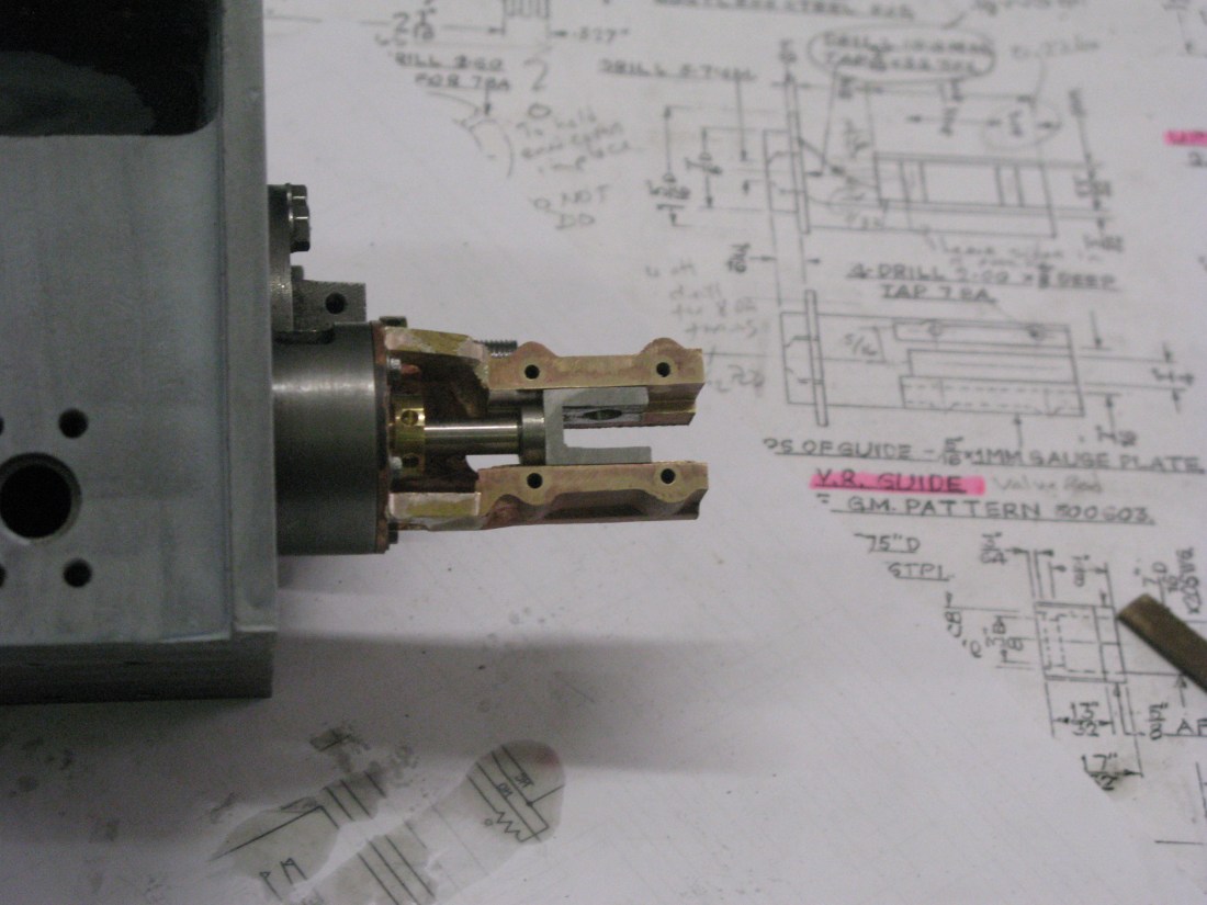
Cross head fitted onto valve rod and in the guide

Finally the top plates fitted to complete the assembly
With the valve guide and crosshead complete it can be dismantled for painting before being finally assmbled complete with the combination lever, yet to be made.
Before starting the combunation lever I decided that the K exhaust needed to be made whilst the block was out of the frames so it could be check fitted to the block before the block was reassembled in the frames. The K exhaust casting covers the whole inner motion so access to the motion can only really be done without the K exhaust fitted. Its a bit of an assembly logic puzzle. See the new chapter for the K exhaust.
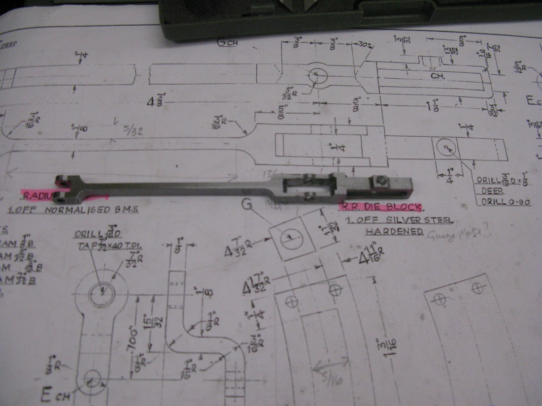
Combination lever and Radius rod
The combination lever is made from 1/4″ x 1/2″ BMS bar. Quite a bit of machining to do as there is nothing “square” about it. I decided to use my little CNC mill to drill the holes for the pins and mill the outline shape. After this was done the rod could be reduced in thickness to 7/32″ and then relieved down to 1/8″ for the the last 2/3rds of its length towards the pin that connects to the union link. That was the plan.
The contour of the rod completed
Milling down to 7/32″ and relieving down to 1/8″ on the first side
The jig have done the contour was transfered to the mill to allow the width to be machined down tp 7/32″ and the lower end relief machined. By removing a holding screw and using a jewellers clamp a couple of times allowed the whole side to be done.
It was then turned over on the jig and with suitable packing under the relieved section the opther side was mileed in the same fashion.
The final operation but one was to open out the holes and ream them to size as shown above, leaving only the oil way to be drilled in the top (left hand side as viewed)
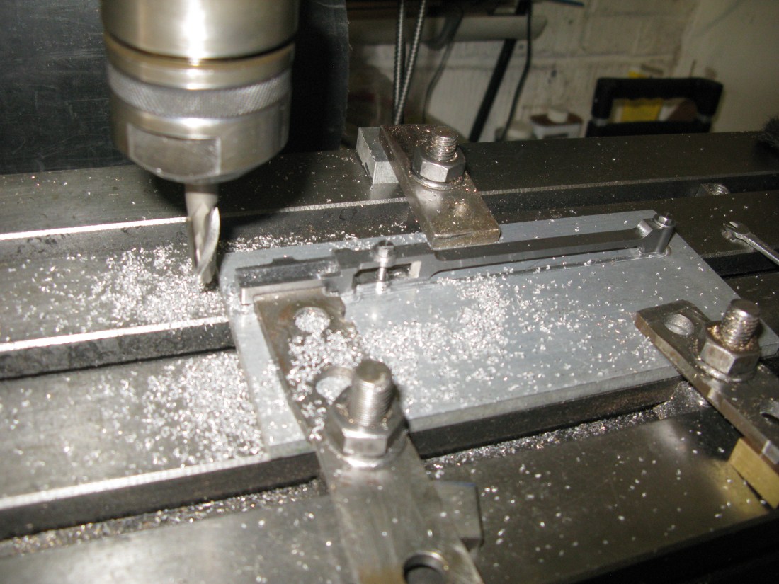
The radius rod employed the same machining sequence as the combination lever, i.e bolting the work down onto a sacrificial plate and milling the contour of the rod by CNC. Once the contour was finished the assembly was relocated onto the mill to machine the the lifting lever slot.

Having done that the assembly was then put into the vice to machine the reliefs on either side doing one side first and then turning the rod over to complete the second side.
The next machining operation was to reduce the sides of the lifting arm slot so the width was 1/4″, down from the 7/16″ width. The clamp on the plate also provided a stop against the rod against which the cutting forces could be resisted as the clamping bolt onto the plate was not sufficient by itself being only 5 BA.
Finally the last machining task …… to mill the slot in the fork end……..

……… giving a finished rod.
The rod assembled in the expansion link…….. free movement all OK.

Drop Link
The drop link is a small and difficult piece to make because of its Z like profile in one plane and the usual link pin radii in the other plane. Its is also not of uniform thickness and the bend radii are not all the same. So how to go about it?
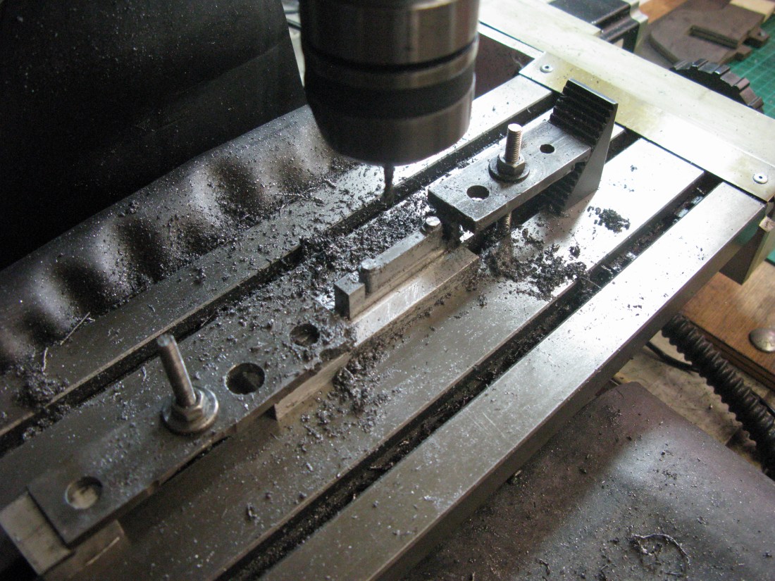
Well my solution was to use my little CNC mill to mill out the Z plane profile then turn it through 90 degrees and mill the link pin contour and finally drill and tap the hole for the fixing pin of the cross head and then the hole for the link pin that connects to the union link.
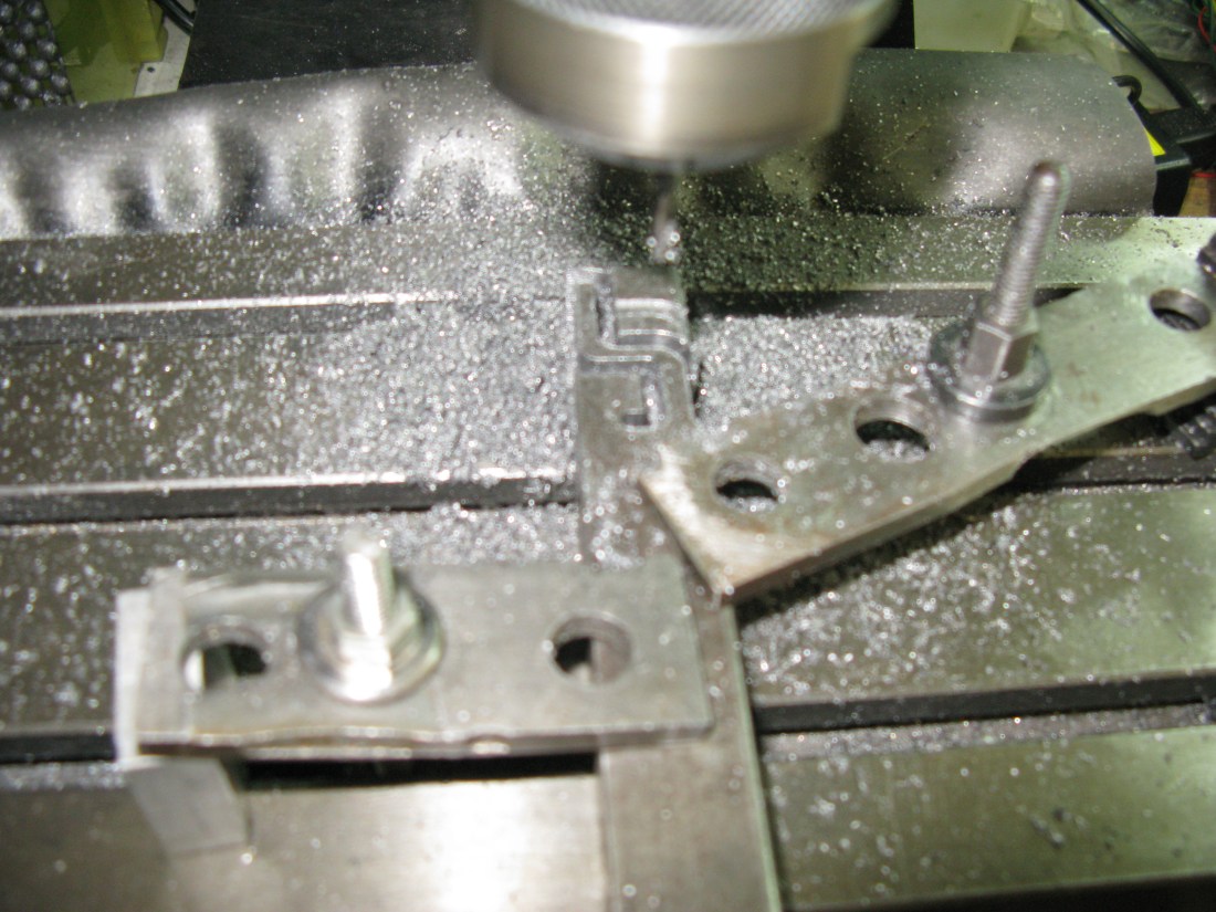
Milling the Z shaped slot
The link was machined from 3/4″ square MS and as the link widest point is 7/16″ the Z slot is not machined all the way through. When it is turned through 90 degrees to do the link contour it is therefor set over to one side of the material and this enables it to be held in place by the un-machined side for the full depth of the link enabling the contour to be machined. There was however a slight snag. The contour was machined with a long series 1/8″ slot drill and it cutting length was short of the 41/64″ depth required so it had to be parted from its mother stock by hand saw and then filed to finish.
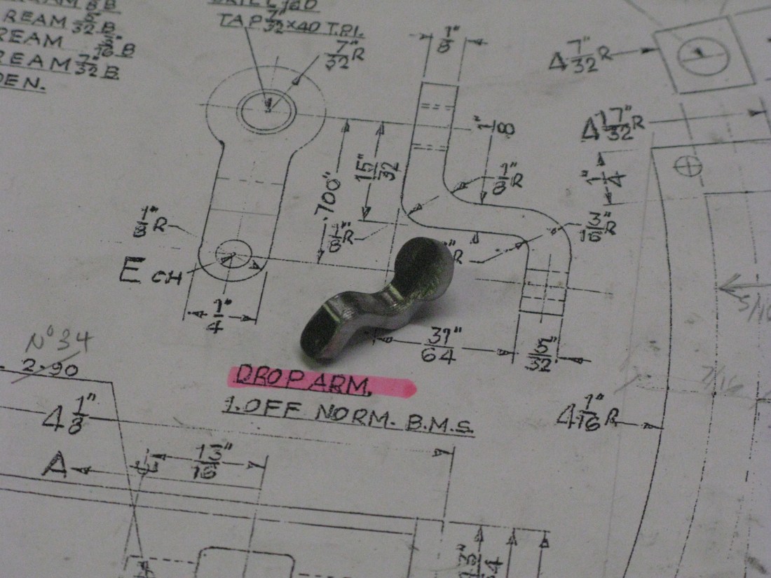
The drop link before having the holes done
Union Link (Anchor link)
The Union link iks called the anchor link on the drawing, I am unsure which is the correct terminology but most Walschaerts drawing I have seen call it the Union link so that’s what I will stick with.
Its manufacture followed the same process steps as the combination lever, i.e. milling its contour on a sacrificial plate, reducing it to the correct thickness and machining the reliefs and finally machining the forks.
Machining the union link profile on the CNC mill
The link was machined from 1/4″ x 1/2″ BMS bar and as can be seen on the photo above there is material below the contour that will have to be machined away to get the required width of 5/16″ across the forks.
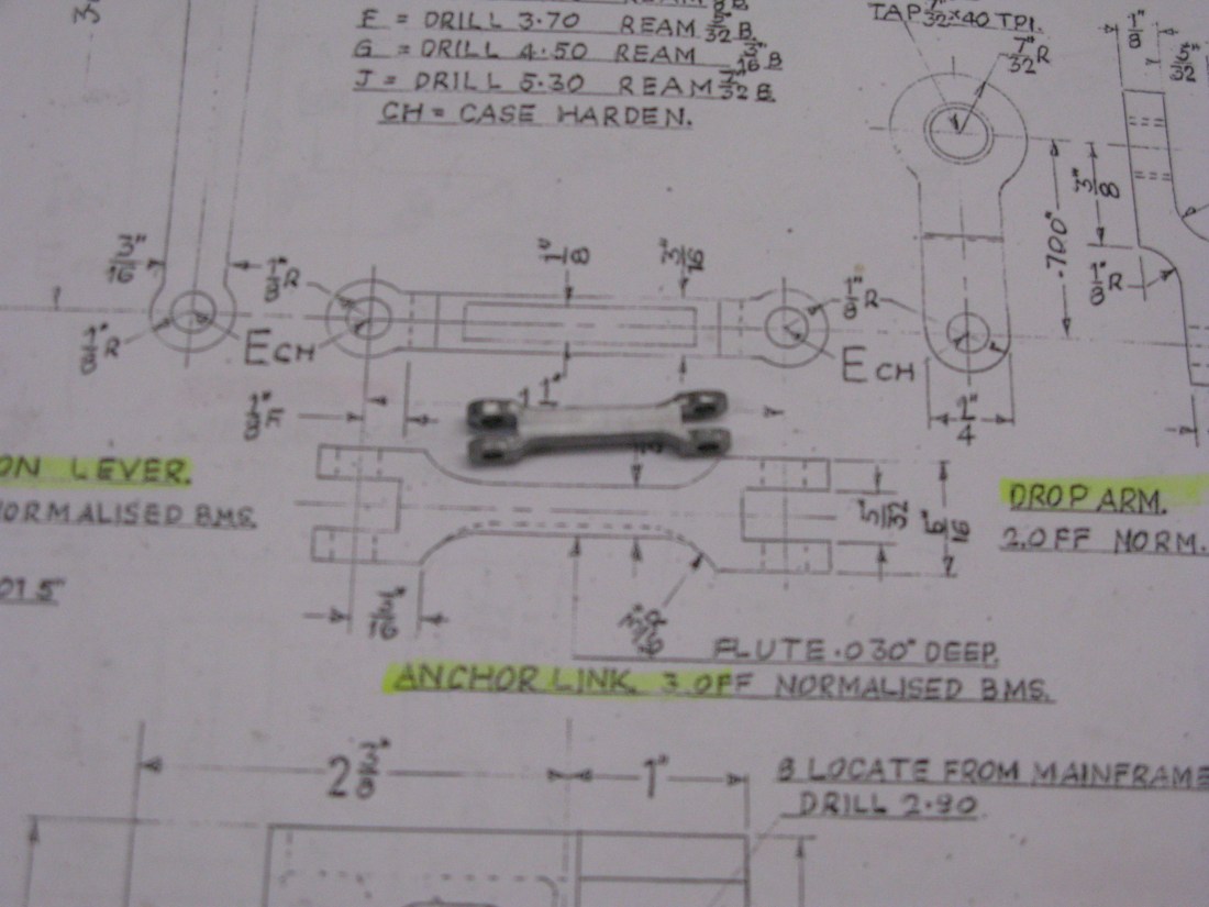
The finished link calls for a flute on one side but as this one is for the inside motion and will not be visible I decided not to put the flute in.
Once completed it was trial fitted to the valve linkage assembly as shown below:
which turned out to be OK and now only requires the pins to be made for the connections, two on the combination lever and one for the drop arm.
Motion assembly
Now for the tricky bit. Assembling the motion and installing everything between the frames. There is no way that the assembly can be done with the cylinder block in position. There is just too much to be done in too little a space for normal hands so I chose to do as much of the assembly out of the frames as possible. It was suprisingly easy to get the start all wrong and I had a least three goes before finding a sequence that worked.
I started with the cylinder block with the valve guide fitted as this is bolted on with bolts that become virtually inaccesible when the K exhaust is fitted. Then I found that the top slide bar had to go on before the K exhaust as well as the top slide bar fixings are also inaccessible at the cylinder end. To check the slide bars were all aligned squarely the cylinder block had to be put back in the frames and the top slide bar aligned with its fixing holes on the motion plate before tightening the fixings at the cylinder block end. Then the block is removed from the frames to continue only to find that the lower left hand slide bar fixings are also inaccessible at the block end because they fouled the valve guide casting. So back to the start! The lower left slide bar is fixed to the upper slide bar then that assembly fixed to the cylinder block and the block put between the frames to check the alignment (with the cross head on the piston rod). The upper slide bar fixings are then tightend onto the cylinder block. With the block removed from the frames the lower right slide bar is then fitted. Now the K exhaust can be fitted and bolted to the cylinder block.
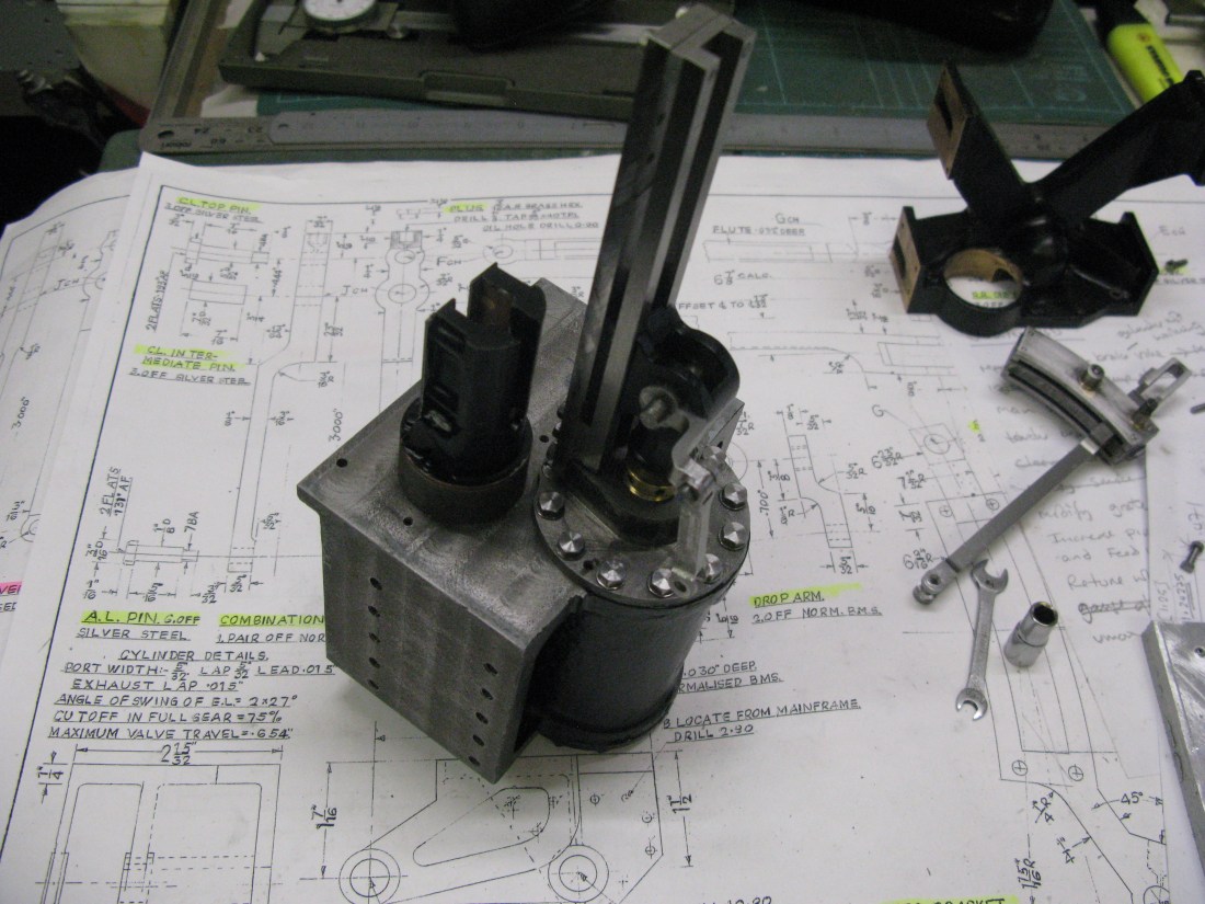
The first assembly stage
The K exhaust is now fitted over the valve guide and bolted to the cylinder block. The combination lever is then fitted to the valve guide cross head and the valve guide cross head screwed onto the valve rod by turning the valve rod at the front of the cylinder using a screwdriver in the rod machined slot. The union link can now be fitted to the combination lever and drop link which is temporarily held in place by the cross head pin. Finally the radius rod is fitted to the combination lever.
Stage two of the assembly
Remember to check the radius rod is the right way round! look at the photo and see mine is upside down, the oil hole should be on the top. I discovered my error after mounting the assembly in the frames and had to take it all out again!
Now the whole assembly can be manipulated into the frames feeding the radius rod through the motion plate and all bolted in place. Do ensure the expansion link left hand plate is in its bearing before mounting otherwise it might not be able to be fitted with the radius rod through the motion plate.
The expansion link can now be assembled around the radius rod and its right hand trunnion bolted in place.
Now it should be possible to move the valve back and forth by pushing/pulling the expansion link with the radius rod at bot thop and bottom of its travel.
There is one worry that I noticed in checking the valve movement and that is the radius rod pin connecting it to the combination lever has to have its “flats” horizontal other wise the pin head will catch on the fixing bolts holding down the valve guide cross head plate. Providing a reduced nut is used on the pin the other side is clear.
Having now (much later) mounted the driving wheels in the frames and connected the front driver con rod and eccentric rod I found that turning the wheel set it jammed about mid travel of the piston both forward and reverse. This turns out to be a problem with the clearance of the combination lever in the radius rod fork as at the extreme angular tavel of the combination lever it comes up against the bottom of the fork even though the radius rod is made as drawn.
So the raduis rod will have to be taken out to give more clearance to the bottom of the fork which is a job easier said than done.
Having modified the fork I still found the motion jammed up when in reverse but not in forward motion. It looked as if the pin head in the top of the combination lever connecting the radius rod was catching on the bolt heads that hold down the plates that keep the valve cross head in it s slide. Rather than risk the possibility of the jam occuring due to the pin turning in its hole (the pin head is two flats on the diameter of the head) I decided to modify the pin so that it was screwed into the radius rod fork without a head which was easily done by tapping one side of the radius rod fork 3 BA and opening out the holes in the comination lever and radius rod to 3 BA clearance.
Having done this believe it or not there was still a jamming problem in reverse motion. Eventually I located the cause as being insufficient clearance in the expansion link at the top (i.e. in its reverse position) and the radius rod was jamming. So everything was dismantled again and the expansion link machined to give more clearance by another 0.020″. On reassembly everything moved as it should.
I think I can now say the inside motion is satisfactory but the final test will be when the reversing gear is made and fitted so the reversing arms can be pinned in position and held firm whilst the motion moves.
