Time to have a go at the wheels, the driving wheels to be precise as a start.
They are cast iron and I do not intend to fit steel tyres which is an option on the drawings. The wheels are flat, that is, there is no boss on the outside for the axle and drive pin the whole wheel being flat with the rim, although the castings come with bosses as the wheel set is common with other loco’s.
The leading and trailing wheels are different to the centre driving wheel in that the balance weights are of a different size. I started with the leading wheel set.
The OD of the wheel is 7 3/8″ and that means it can only be turned on the faceplate of my Myford in the gap of the bed. This presented the first problem of how to get a flat face that could bolted to the face plate as a boss protruded on the front side of the wheel and the casting sprue on the other side.
My solution was to bolt the wheel on spacers to the mill bed front face down and mill the rear face flat at the rim and across the sprue area. This was just a clean up cut.

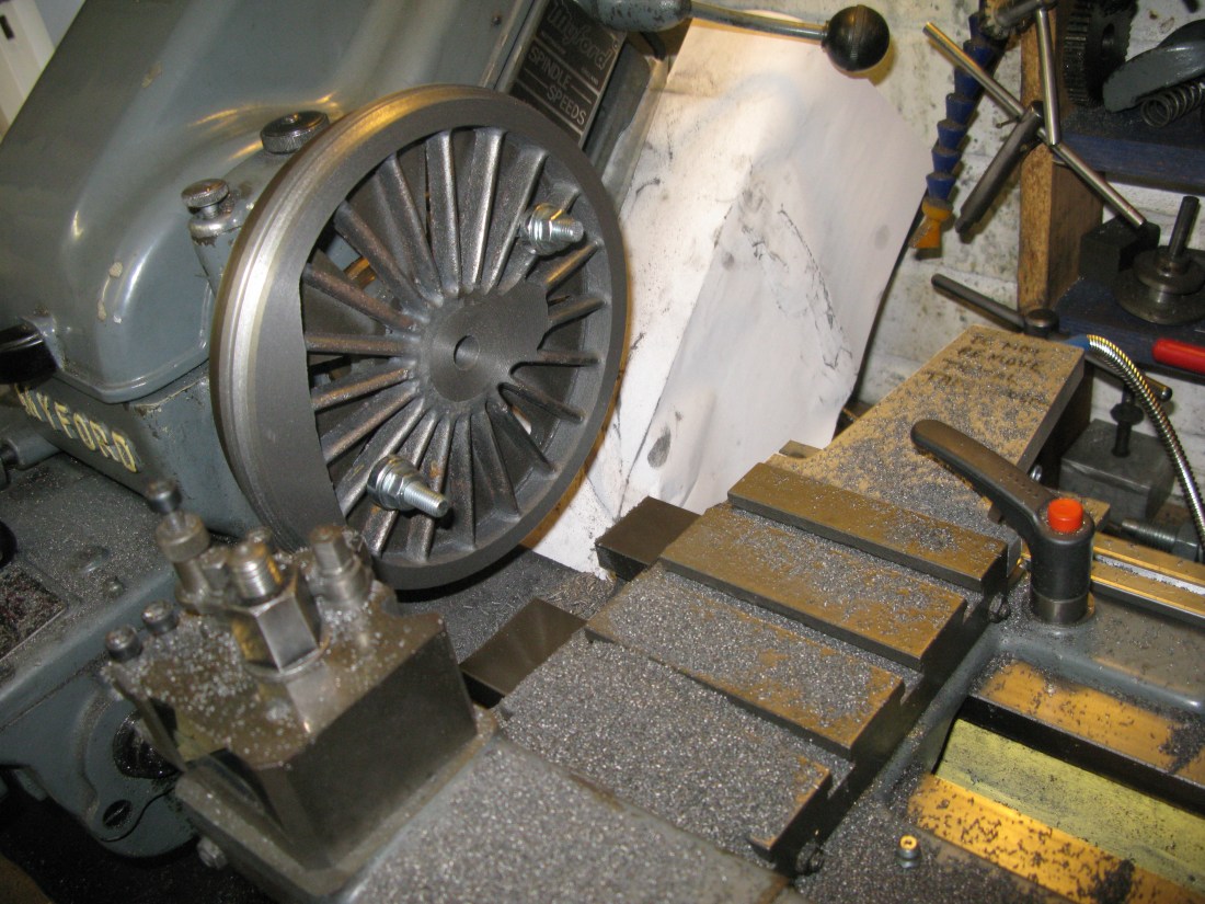
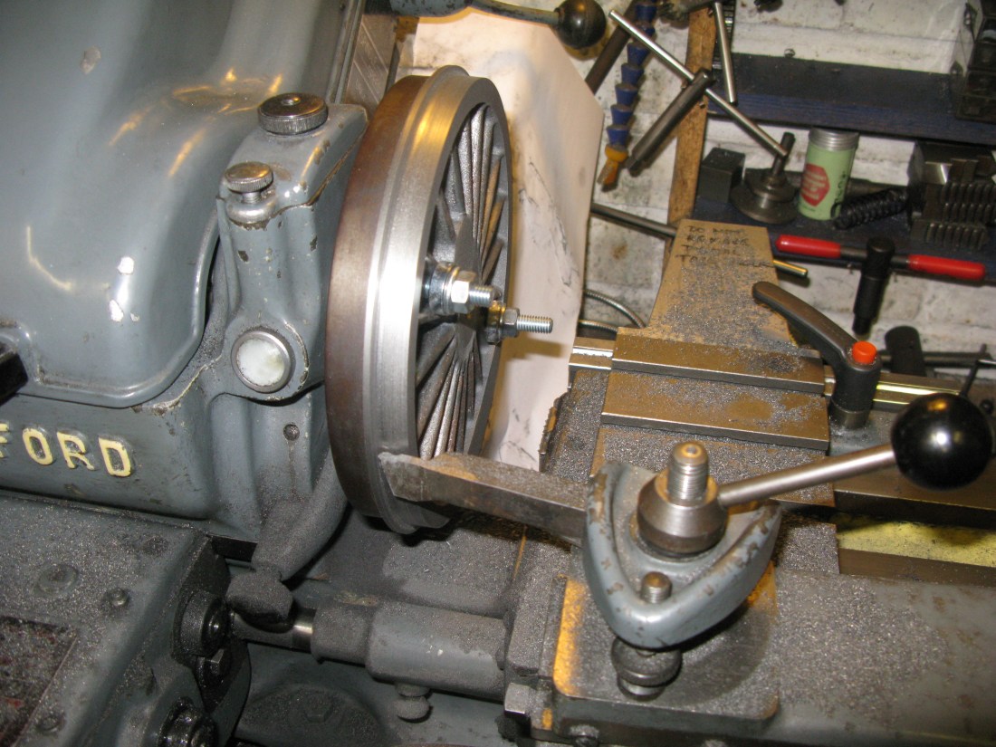
With a flat face, the wheel was bolted to the faceplate and set so the the front inner rim ran as true as the casting would allow. It can not be easily checked with a DTI as the balance weight is cast in flush with the rim so the inner rim is not a continuous circle and the casting is not a nice smooth finish.
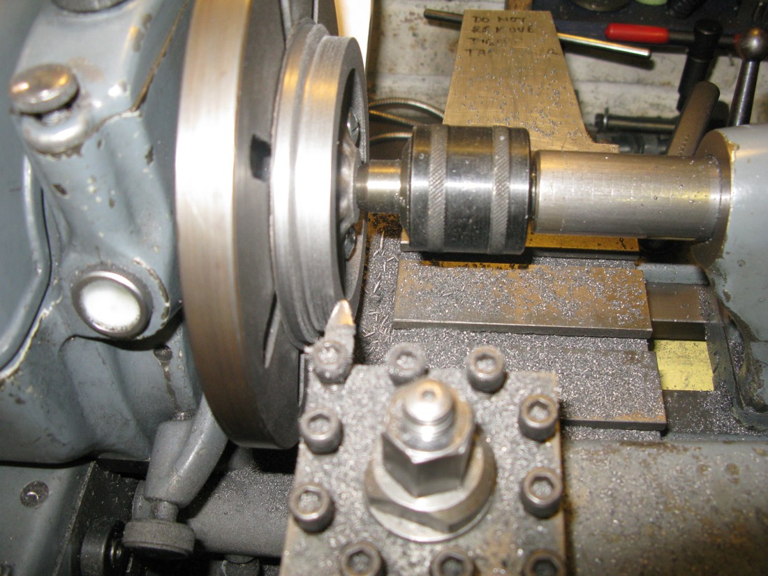
Once satisfied it was as true as I could get by running the spindle and just observing the wheel inner rim to see how circular it looked (that’s the bit that will show when the loco is running), clean up cuts were taken on the diameters and face of the wheel. This involved tool changes as the bolting arrangement prevents the tool facing accross the whole wheel. To do the area of the bosses I drilled a 1/2″ hole and used the boring bar to face off the central part of the wheel, The hole just helps the boring bar start to cut. Why a boring bar? The tool needs to clear the holding bolts.
Having checked there was sufficient width on the casting the front bosses were machined away and the rim machined to the same level. This formed the datum for the wheel width and the back of the wheel that protruded above the face plate was machined to give the required wheel with of 17/32″.
The outer diameter of the rim was then turned down to 7 3/8″ and rough cuts taken to bring the tread near to size.
The final tread has a 2 degree taper up to the flange and the flange has a 20 degree taper both meeting by a 0.070″ radius in the corner.
Using the top slide set at 2 degrees the tread was gradually machined down to give a 7 1/8″ diameter at its outside edge. Not an easy thing to measure even though I have a micrometer that covers that required size. Also the full width of the tread was not machined as allowance had to be made for the machining of the 20 degree slope of the flange.
The 20 degree flamge angle could not be achieved with the same tool used for forming the 2 degree tread as it was too far away from the work with the top slide set over to 20 degrees so a long tool had to be employed to reach. This had the 0.070″ radius so it could do the web radius turning as well. The process required numerous swapping the top slide between 2 degrees and 20 degrees to form the tread and flange angle so they merged properly. Lastly the 1/32″ 45 degree angle was machined off the tread outside edge.
The flange 3/64″ top radius was done with a swiss file by hand rather than make a form tool.
The bore for the axle was then done. This was bored so that the axle (in this case the crank shaft) was a good sliding fit rather than a pressed on fit. I chose this because I reasoned it would assist to be able to move the wheel when aligning the wheels and crank to the 120 degree divisions. I planned to use Loctite and a pin to secure the wheel in postion on the crank.
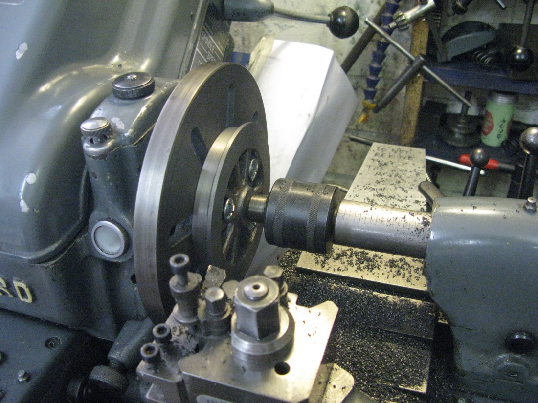
Finally the wheel was turned over on the face plate to clean up the rear to the previously turned reference and the inner boss cleaned up.
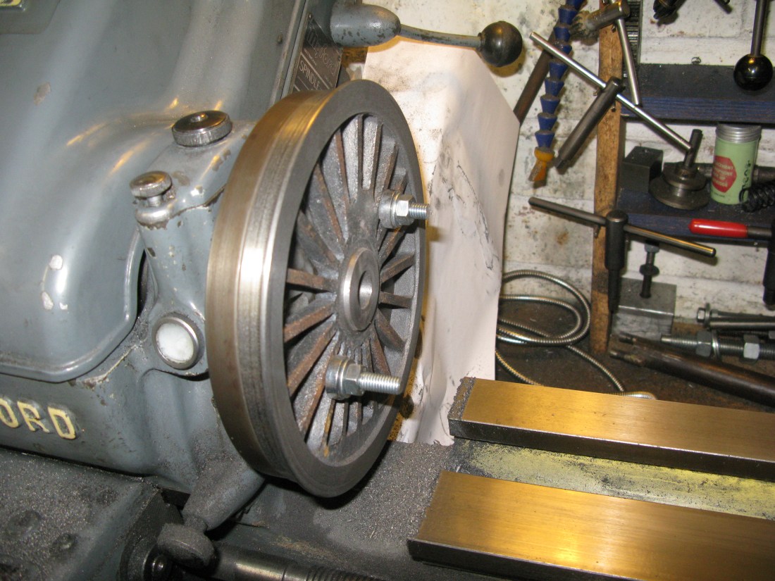
Back face and boss cleaned up to finish the wheel machining
All that remains to be done is to fettle the spokes ready for painting and drill for the drive pin, however this last item will not be done until all 6 wheels are done so all the pins can be done as a batch.
Just another five to do.
As an afterthought I decided to double check the wheel standard dimensions against the GL5 (ground Level main line society) standard. There are descrepancies. The tread angle for GL5 is 3 degrees not 2 and the chamfer at the tread edge is 30 degrees not 45 and extends 1/16″ into the tread. Also the width is 1/2″ for GL5 against 17/32″ as drawn and the root radius is 3/32″ not 0.070″. The drawings indicate the as drawn dimensions are as published in the Model Engineer January 1980.
A search of the web results in a number of slightly different dimensions so I decided to keep to drawing.
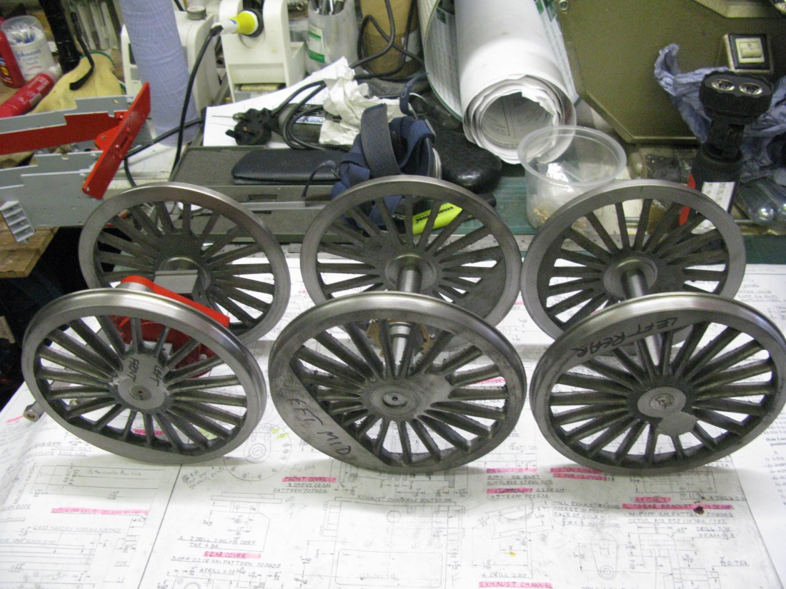
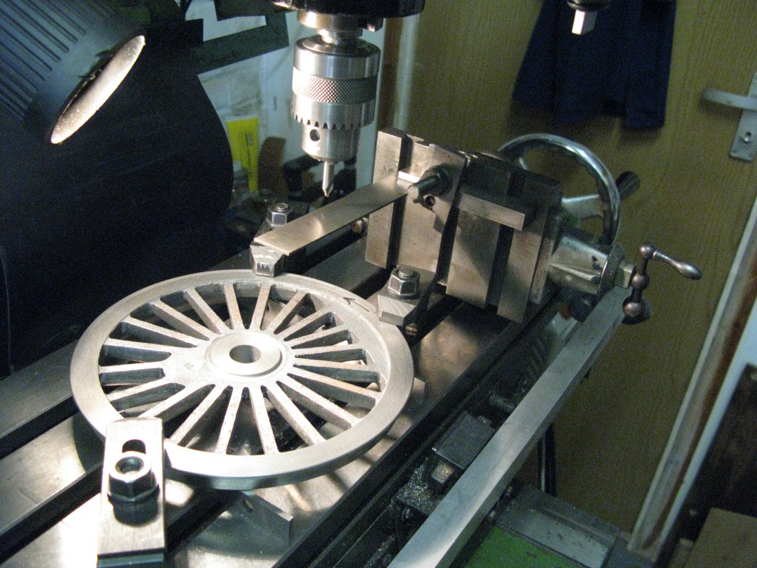
A set of drivers still to have the crank pin positions drilled

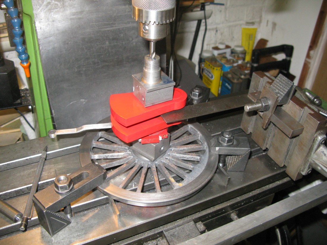
Aligning the centre line for the crank pin on the mill bed
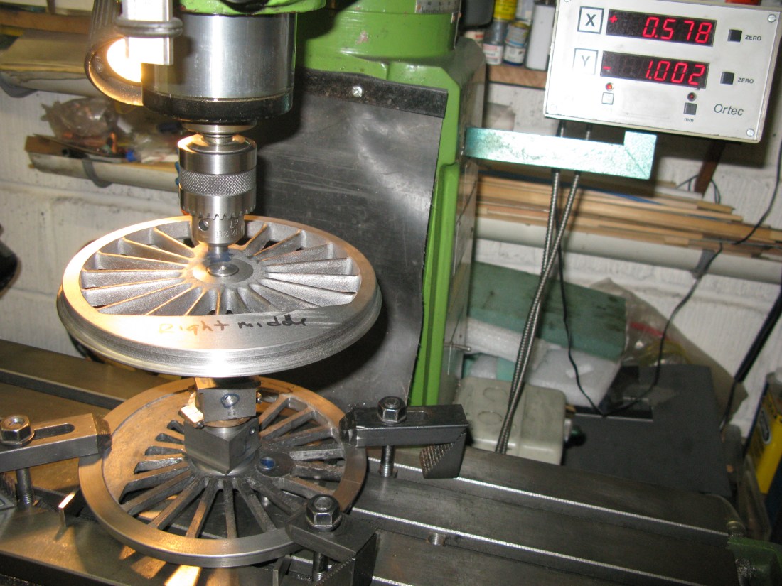
The machining of the hole for the drive pins was done by first marking out the centre line of the pin and then setting that line square on the mill bed using an optical viewer.
The wheel was then centered under the quill using the bore centre finder and the DRO’s set to zero. The mill table was then moved by the required distance (1 5/32″) to the centre of the drive pin. Using a centre drill first and then an undersize drill for the required pin diameter the drive pin hole was drilled. It was finally reamed to the required size for the drive pin. They are different for the centre drive wheels to the leading and trailing wheels.
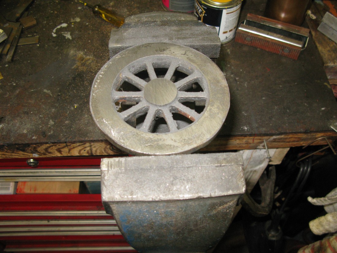
The drive pins for the centre drivers were made first and the first attempt at press fitting the pin into the wheel was a disaster. The pin was 1 1/2 thou oversize which should have resulted in an acceptable press fit. However in pressing it in using my garage press (12 ton) resulted in the wheel cracking at the boss. The photo below has the cracks highlighted in black. They are hairline cracks right through.

The reason for the disaster was that I had the wheel mounted on the support plate and had forgotton that the axle boss is 1/32″ proud of the drive pin boss, the axle boss and outer rim of the wheel being level. So when I pressed the pin into the hole there was no positive support for the casting immediately below it. Lesson learnt, and the other wheel had its pin pressed in OK although I did use the bench vice to exert the pressure as it has more “feel” for the process than a hydraulic ram.
I pondered having the cracked wheel welded but advice received was that the process could result in further cracking as the weld cooled and that the weld can be diamond hard and so making it difficult to clean up. The cost of repair was likely more than a new casting as well. So a new casting was the way forward.
The new casting has been machined, so I am back with six wheels again.
The crank pins are machined from silver steel and this a straight forward turning exercise. The front drivers have a 2 BA tapped hole for a C/S allen headed retaining screw and washer. The rear drivers have a 1/4″ x 32 tpi thread on the end for a retaining nut. The middle driver has no retaining method relying on the return crank which is fitted on the end to keep everything in place.
The pins are all pressed into place the interference fit being no more than a thou and half.
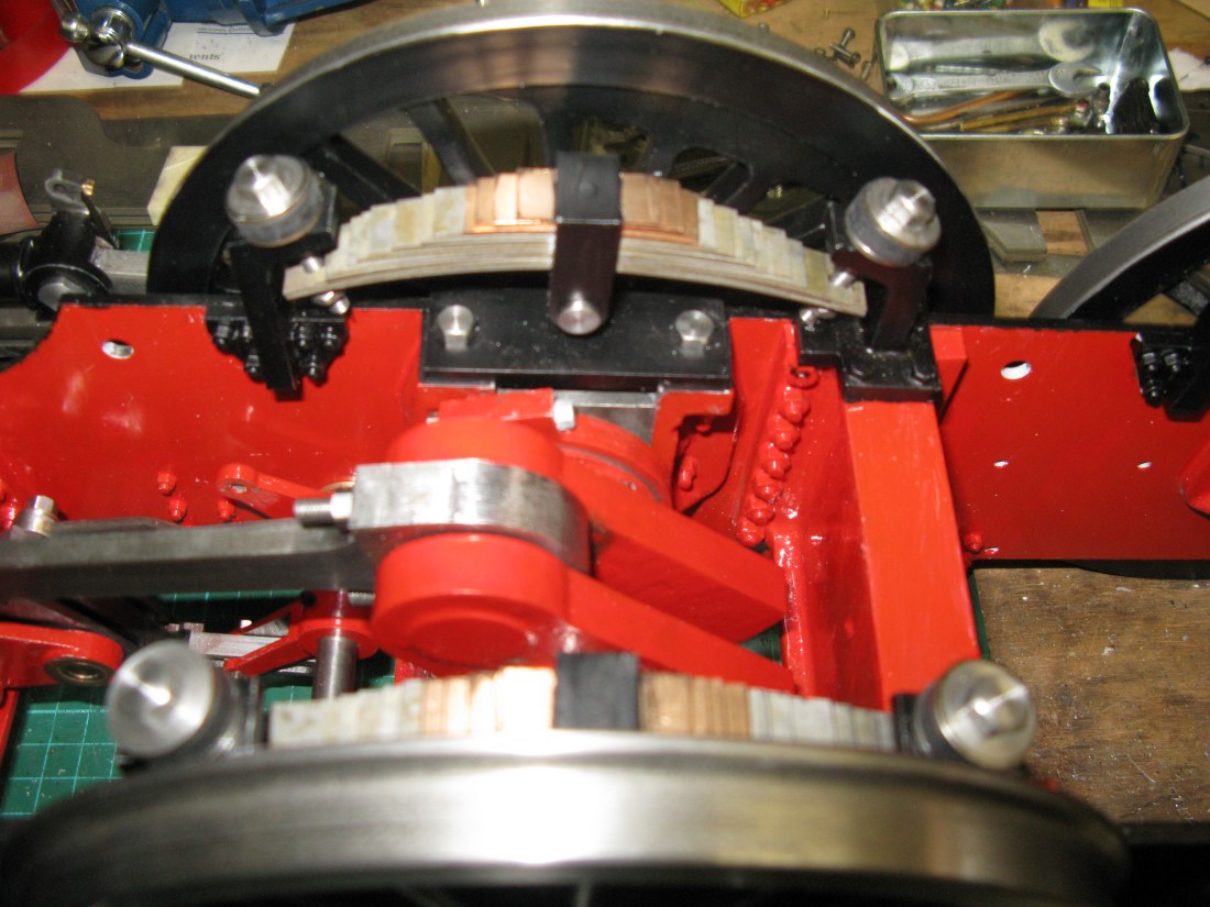
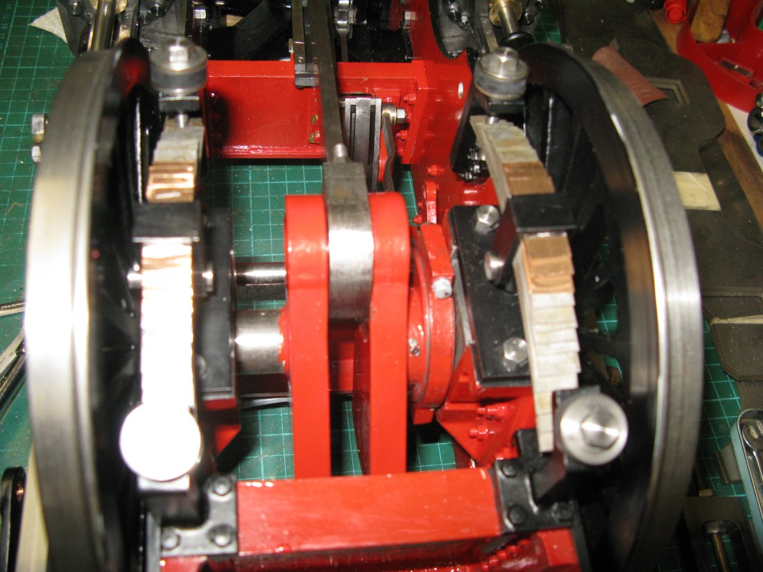
Thirding the wheel sets
Strange to talk about “thirding” , its usually quartering but with three cylinders the wheels are set at 120 degrees not 90 degrees.
All sorts of jigs and methods have been devised for quartering but very little can be found for thirding. I considered a number of options but I came down to two, the first using height gauges against the crank pins with the wheels set between centres using the dividing head and its tail stock on the mill table and the second to use the mill and DRO and a bit of trigonometry. In the end I decided on the later.
First to explain the trigonometry. The drawing below is a wheel with its crank pin and the other wheel’s crankpin set at 120 degrees. In my case the left wheel leads the right wheel in the forward motion (anti clockwise). The PCD of the crank pins is 1 5/32″ radius. With the left wheel crank pin set on an axis line (in this case the X axis …… drawn vertically which is unusual, but I will explain later on the right wheel crank pin creats a right angled triangle with a 30 degree angle at the axle.
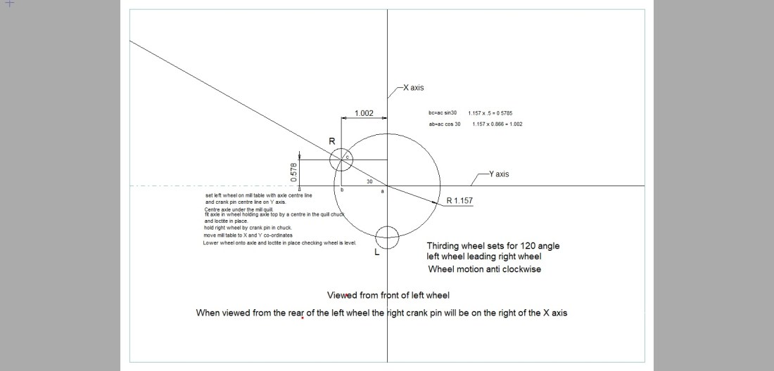
Sorry for the small image, its my CAD drawing after file conversion to get it in a format to fit on the page.
With a right angled triangle knowing the angle and the hypotenuse length the X and Y sides can be worked out from opposite/hypotenuse = sine of the angle and adjacent/hypotenuse = cosine of the angle. So now I have the X and Y cordinates of the right hand crank pin relative to the axle centre line.

Aligning the crank pin and axle on the X axis with optical viewer
The left hand wheel was aligned so the left hand crank pin and the axle centre were aligned on the X axis of the table, the reason being that if set so the alignment was on the Y axis the Y axis movement of the table was insufficient to verify that the crank pin was indeed vertical with the axle and X axis. This arises as the crank pin sits in a table slot even though the wheel is on parallels to raise it up just sufficent for the crank pin not to bottom out. The whole wheel radius was used to verify the alignment as the longer the line being checked the more accurate the alignment will be. (On second thoughts I perhaps could have turned the wheel through 180 degrees so the Y axis movement was away from the throat).
Aligning the axle centre under the quill
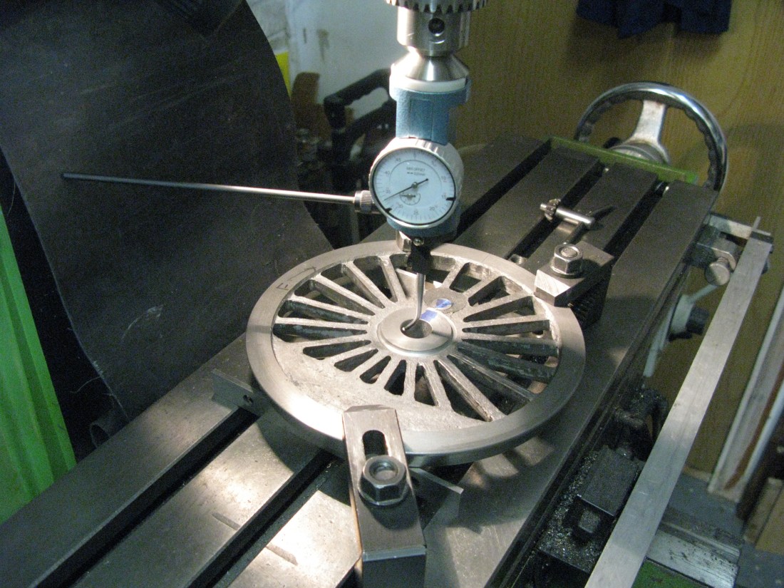
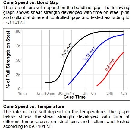
Once aligned the axle centre was then aligned under the quill and the axle inserted with Loctite 603 and the top of the axle held in place by a centre in the chuck thus ensuring it was vertical. This was then left for the Loctite to cure. A minimum of 30 mins is required but I left it for a couple of hours which as the Loctite charts below show how the strength of the bond developes dependant upon gap and temperature.


Axle inserted with a centre holding the top true ( the bolt is just holding the bearing up)
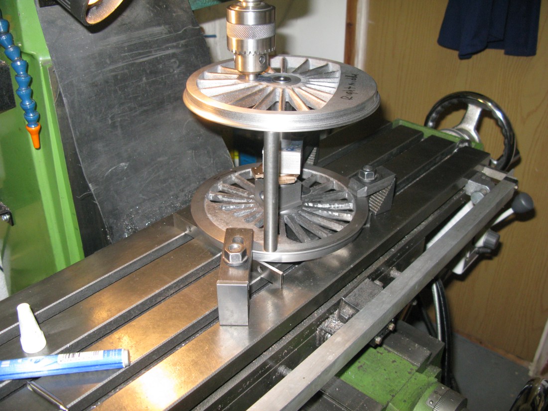
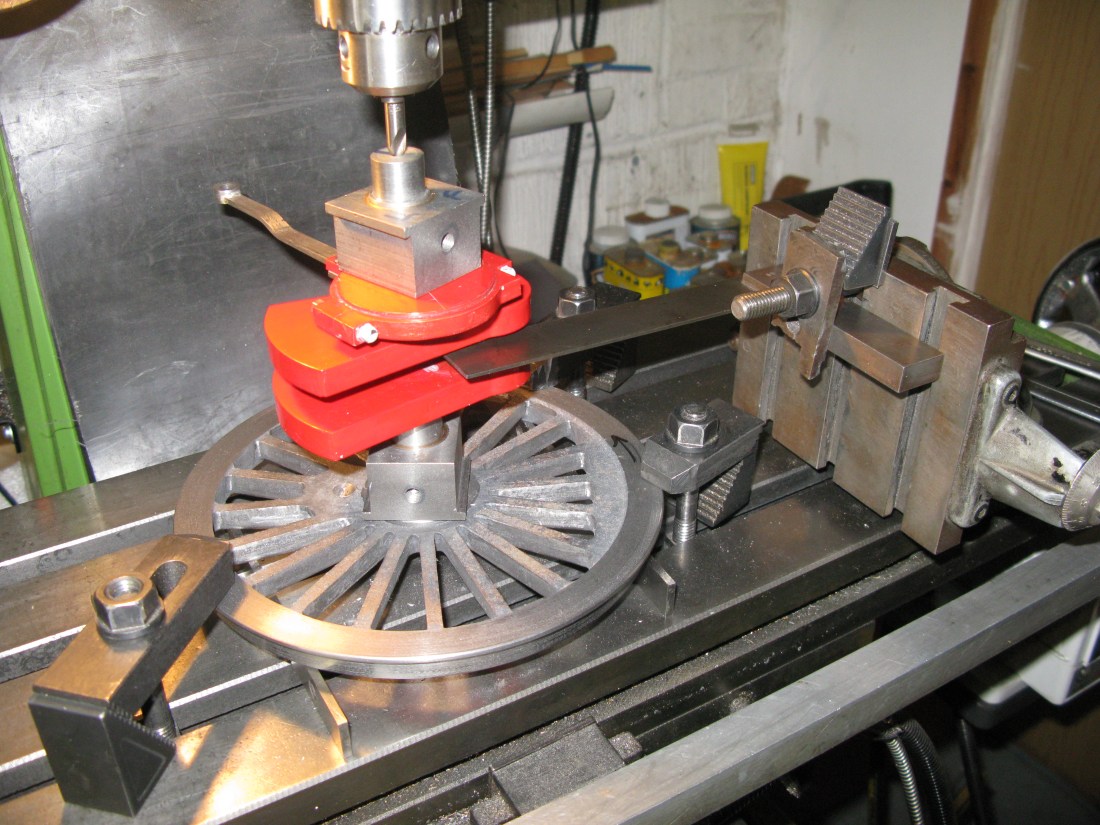
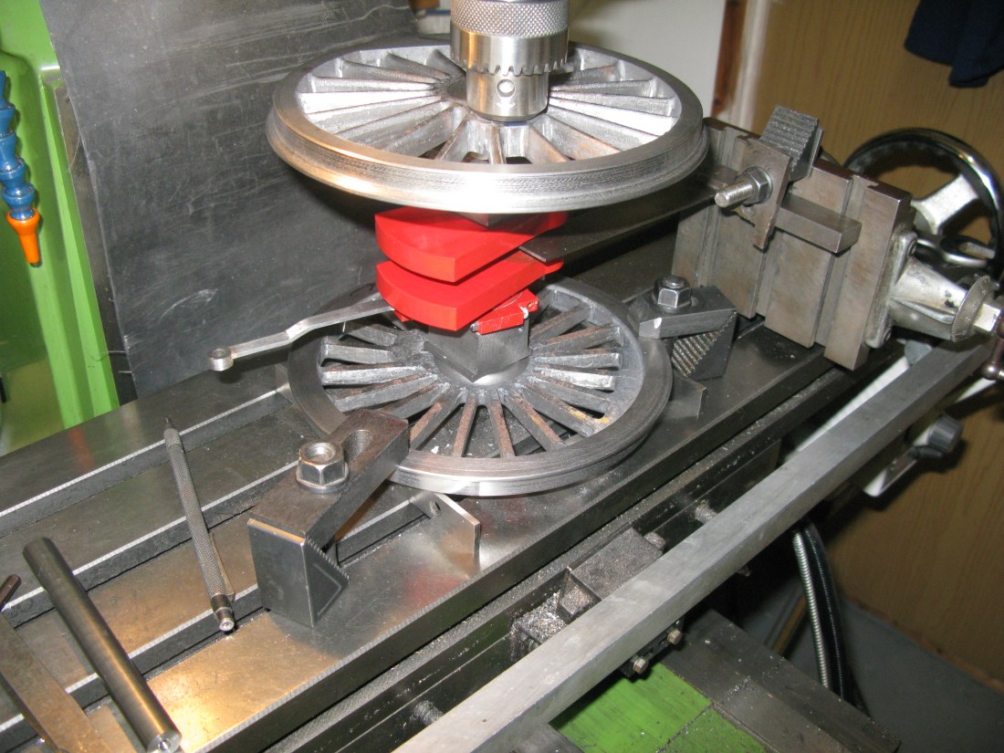
The next stage was to fit the right wheel by holding the wheel by its crank pin in the chuck. The table was moved by the X and Y coordinates as measured on the DRO and with Loctite on the axle the wheel carefully postioned and lowered onto the axle using the quill handle.

Wheel about to be lowered onto the axle
With the wheel fully lowered the back to back was checked using a gauge at exactly 4 11/16″ long.
Checking the back to back
The tolerance on the back to back measurement is +0.020 and -0.00 and this wheel set turned out to be 0.012″ oversize.
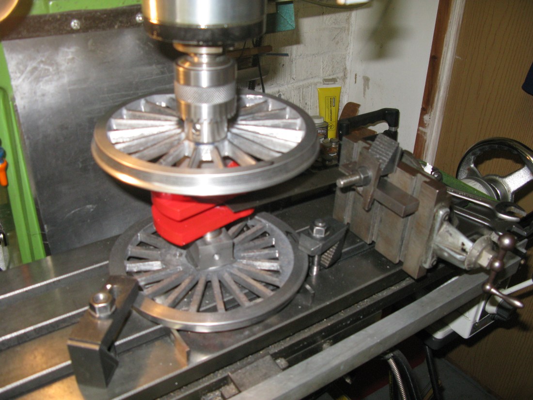
another view of the fitted wheel with the DRO measurements visible.
I do like this method of setting the wheels, its accuracy is only dependent on getting the initial alignment on the table right and no jigs etc have to be made.
Putting together the rear set of driving wheel I narrowly avoided disaster as I had aligned the the top wheel and put in place with Loctite only an hour or so later to realise I had not put the bearing blocks on the axle! Releasing the chuck there was a small amount of turning movement of the wheel on the axle but I could not work it off. So I resorted to using the torch to heat the wheel up softly until I had a lot more turning movement and then I could work the wheel of the axle…..phew!
Having cleaned up the axle and wheel bore of the Loctite residue and putting the bearing blocks on the axle the wheel was re-aligned and fitted OK.
The front driving wheels required a slightly different procedure to set up because it has the crank axle and all three crank pins need to be at 120 degrees apart.
I started by centering a wheel under the quill on the mill table. This wheel was only going to serve the purpose of holding the axle in place as it was the wheel at the top of the axle which was to be put in place with Loctite.
I needed to align the centre of the crank axle along the X axis so that the wheel being fitted could have its crank pin placed at 120 degrees using the X and Y dimensions as before.
To align the crank axle I employed my Myford vertical slide bolted to the mill table so that the slide gave a horizontal travel. With a square clamped to the slide the square was set to touch a centre drill in the chuck whose shaft diameter was 1/4″, from here it was a simple matter to move the slide forward 1/8″ so that the edge of the square sat on the X axis centre line.
The slide was then move back 0.406″ being half the diameter of the crank pin. The axle can now be placed in the bottom wheel and the axle crank pin placed up against the square with the top of the axle held central by a centre in the chuck. The axle was now centrally aligned. The mill table was then moved by the X and Y co-ordinates to enable the wheel to be fitted. (removing the centre of course).
Axle correctly aligned with the crank pin on the X axis.
With the wheel to be fitted in the chuck it was located above the axle and lowered into position having put Loctite onto the axle.
Once the wheel was set in place the assembly was turned over and the axle centred under the quill using a centre in the chuck and the crank pin against the square.
Finally having moved the mill table to the X and Y cordinated the last wheel was fitted.
The next job on the wheels was to give them a coat of paint. Undercoat/Primer and then a top coat.
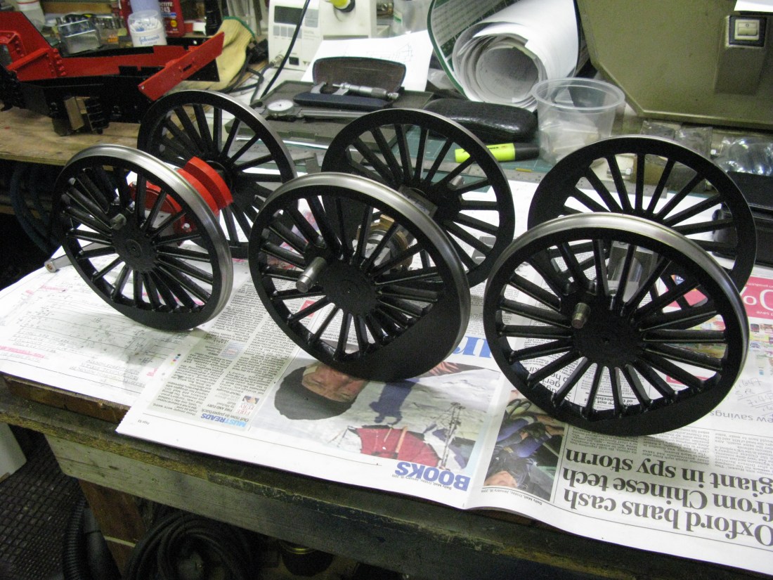
At this stage the wheels are not finally pinned. I will do this once they have been checked in the frames with a spacing jig to ensure all the crank pins align correctly.
Cartazzie axle wheels
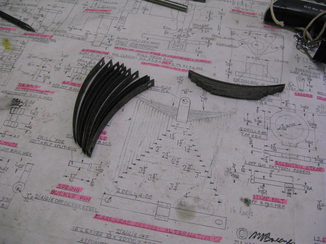
Before turning the cartazzie axle wheels I made a start on the axle springing. It’s dummy springing using a coil spring inside the buckle of the cast dummy leaf spring.
The spring hangers are a simple turning job. The dummy cast leaf spring needs cleaning up and that is not quite straight forward as the castings are not finished too well and a bit out of square, however a bit of latitude exists as the drawing is not fully dimensioned.
The pin, (over which the spring fits), that fits into the top of the sliding plate is drawn as 1/4″ diameter but I made it 3/16″ as I could not source a suitable spring that had an internal diameter of 1/4″ and external diameter of 5/16″ to fit in the counter bore of the dummy spring. This counter bore is slightly smaller than the 9mm specified on the drawing which would not fit into the buckle material of the casting without breaking through the sides.
The wheel drawing has a few issues with it. The wheel bore is specified as reamed 1/2″ but the axle is dimensioned at 0. 5645″ As I had already made the axle the wheel bore was made to fit. The barest of dimensions for the wheel are shown, the overall diameter and the wheel tyre diameter and the width of the wheel and flange although there is no mention of the 2 degree tyre angle or the 20 degree flange angle and as drawn the wheel profile looks square. There are no dimension for the inside and outside bosses. The outside boss is drawn at 1/8″ longer than the wheel width yet the dimensions of the wheel width means it can only be 1/16″ longer. So all in all quite a bit to be careful of.
Hand fileing to remove high spots
Machining the wheel was done on the face plate. First the rear of the wheel was filed flat to remove high spots on the casting. It was then bolted to the faceplate using tapped holes in the faceplate and wide pan headed 6mm screws to hold it in place through the gaps in the spokes. As with the main wheel I try to get the inner diameter of the wheel tread to run as true as possible and then machine the outer diameters. The diameters were first rough machined and the bore drilled to 1/2″. The face of the wheel and boss where also rough machined. I used a running centre against the bore as added security against the wheel moving on the faceplate once the drilling operation was complete.

Rough turning and drilling for the bore.
The flange diameter was then machined followed by the tyre diameter but only enough to allow the 2 degree taper to be put in so the edge of the wheel was just marked by a small cut of the lathe tool at the correct tyre diameter which acts as a reference from which the 2 degree taper is subsequently turned. This small reference cut gets turned away by the small 45 degree taper cut on the finished diameter. The taper was turned with a 20 degree side cut angle and nose radius radius tool to form the flange taper and its root radius in one go. The top slide set at 2 dgrees is used for this purpose.
flange and root turning
The bore of the wheel was then done to fit the axle and then the wheel turned around on the faceplate, centred and and the final width machined followed by the radius on the top of the flange which was put on by hand file.
The facing of the boss had to be done with a different tool as the one in the photo above caught on the fixings and of course the rotating centre was moved back out of the way.
Withe wheels finished they were mounted on the axle withLoctite ready for mounting in the frames.
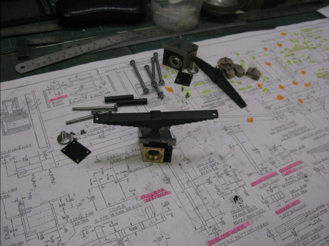
As said earlier the springing arrangement uses a coil spring and cast dummy leaf spring. The bits are all shown in the photos below.

To finish off the cartazzi installation a small dummy oiler is mounted above the top sliding plate. It could be made operational which was my original intention but I found it impossible to drill the small oil hole at an acute angle through the gauge plate material of the top slide as it is quite a length to get it above the area that slides.

The oiler is shown above without its cover plate.
The main wheel set had the wheels pinned once I was happy with the outside rods being fitted and running OK. The pinning was a simple 1/8″ silver steel x 3/8″ long pin fitted on the axle circumference and loctited in place.

Drilling for the 1/” dia. locking pin.
The drilling operation was done with the wheel set clamped to the mill table and a centre drill used first to ensure the drill bit would drill on the circumference of the axle.
Driving wheels springs
The driving wheel springs are drawn as made from phospher bronze 20 swg and 7/16″ wide. They fit into a buckle and there is no drawn means for securing them in place and presumeably the intent is for them to be a press fit in the buckle. There are 16 leafs and the deflection is stated as 0.176″ under 24lb.
To do a rough check on the loading I weighed the boiler and the chassis so far which gave 112 lb. Six times 24 gives 144lb so with the extra weight of the front bogie and water in the boiler I can expect more than 144 lb but some of the weight will be taken by the bogie and Cartazzi axle, so I guess the spring loading is in the right ball park.
Now I am not a great lover of PB springs because I think they loose their springness. Others may disagree. Anyway I decided to experiment with spring steel of the same size. This was duly obtained in an annealed state and a trial spring part built. I say part built as I assumed a full steel spring would be far to stiff.
The leafs vary from 3/4″ long at the bottom to 4 7/16″ for the top two as measured across their bent shape. The top two have slightly enlongated holes at the neds for the spring tie bolts to pass through.
I built up 12 leafs and tested them with a spring balance to see what deflection would occur. This being in the unhardened and annealed state.
The arrangement for testing was to use a luggage weighing device with a digital readout. This was secured agains the quill of the mill and the spring under test connected via a chain and located behind the vice jaws. All I had to do was wind the mill table away from the quill to exert the load and the deflection could be measured from the vice jaws.
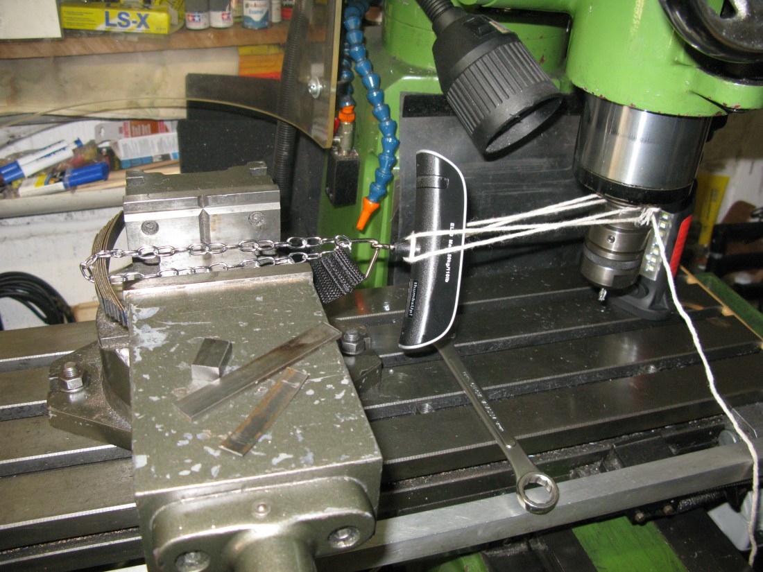
Load testing a partial steel spring
Now there will be a bit of give in the string but at this stage I was only looking to see if a 28lb load was giving a deflection in the right ball park…….. it was not. It was giving only about 0.070″ so it was clear that a totally steel spring was not going to be any good assuming the hardened state would be similar.
The next stage was to explore the use of some PB leafs but keeping the two top leafs as steel. Before trying the PB I decided to harden and temper the two top leafs as whatever arrangment I eventually decided the top two leafs were going to be steel. Hardening was done at 720 degrees C and tempering at 300 degrees C in my workshop oven. To remove the slight oxidisation that occurs I use brick acid which is hydrochloric acid based (about 10%) and after a couple of minutes or so soaking the discolouration can be brushed off and the leaf rinsed in water and dried.
The hardened and tempered top two leafs
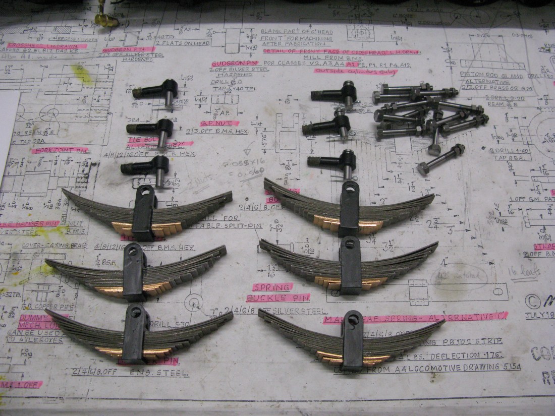
Whilst waiting for PB to arrive the spring support pins and the buckle link pin have been made. The buckle awaits the arrival of the PB as the spring make up needs to be known so the right depth of the buckle can be machined. However, the drawing dimension for the buckle depth does not match 16 leafs of 20 swg (0.035″ actual thickness) so in any event I need to get the correct spring depth before machining.

Spring support pins and buckle link pins
More testing with steel leafs but this time in the hardened state, showed that all but the bottom 5 leafs were required to get the approximately correct deflection so that set the bench mark for the balance to be PB. The PB arrived as a 12″x12″ 20 swg sheet and I used my small guillotine to shear of a couple of strips 7/16″ wide from which to cut the leafs.
Compressing all the leafs together in the vice showed the depth of the buckle should be 16 x 0.035″ (0.560″) so I machined one buckle to 0.565″ and silver soldered the “lid” in place to form the spring aperture. The internal corners were filed square to ensure the top and bottom leafs would fit against their respective surfaces. A trial assembly of a spring proved that the last leaf was impossible to assemble in the buckle and that 5 thou clearance was insufficent. I think this is due to the very slight curvature (very very slight ) that exist across the width of the spring steel and probably occurs during manufacture. The pressure exerted in the vice when checking the depth to mill the buckle cannot be replicated when assembling the leafs. As there is no means of preventing the leafs from movement in the buckle I decided to put a 3/32″ silver steel pin down through the centre. The top of the pin is just burred over to prevent it dropping out should it ever become loose but it is held in place by Loctite. Also the third leaf down need a little slot at each end to clear the spring support pin which is not shown on the drawing.

Trial spring assembled – buckle suport pin end yet to be machined.
But to descibe the buckle manufacture. It was made from mild steel and machined in the form of a H. One end would be rounded to accept the buckle link pin boss and the other capped with 3/32″ steel flat silversoldered in place to form the spring aperture. The two slots were machined with a slot cutter 7/16″ and 5/16″ respectively.
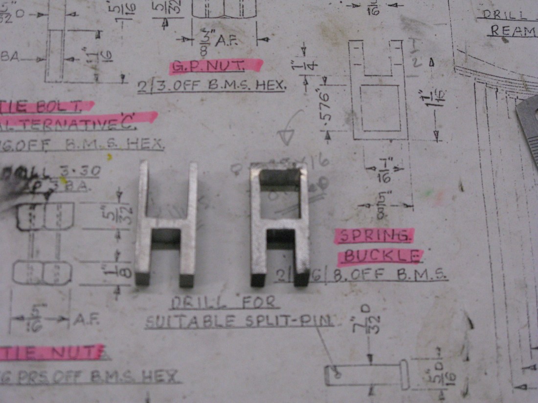
Buckle blank H on the left and with its cap on the right
Once the cap is silver soldered in place the internal corners need cleaning up with a square file (with safe edge) to ensure the spring leaf will sit flat into the corners. (Why a safe edge file? Well it gives a nice sharp cutting edge to the file so a square corner is produced. A safe edge is easily ground onto one side of a square file.)
With all springs assembled attention can be turned to fitting them to the axles.
The buckle pin is silver steel and has a 1/16″ hole at the end for a split pin. The drawing does not dimension the hole size or its position, it just says a suitable hole!
A trial fit of one spring showed up three issues, firstly the hole in the hanger did not allow enough “slop” for the hanger pins to freely fit into the spring and secondly the length of the hanger pin was apparently too long. The former was corrected by putting a drill 1/64″ larger through the spring hanger and the later was resolved by realising there should be a shock absorber fitted under the spring hanger. This was shown on the general arrangement drawing but there was no detail drawn anywhere for their manufacture.
To make the shock absorbers I used a tap washer of 5/8″ diameter with a steel washer either side.
The third problem occured when trying to fit a spring as the spring hanger pins could not be fitted as drawn with their heads inserted from the top. As can be seen from the photo above the hanger brackets foul the line of the spring hanger pins, so they had to be fitted from below. They have a nut and lock nut as drawn so I think they will be secure.
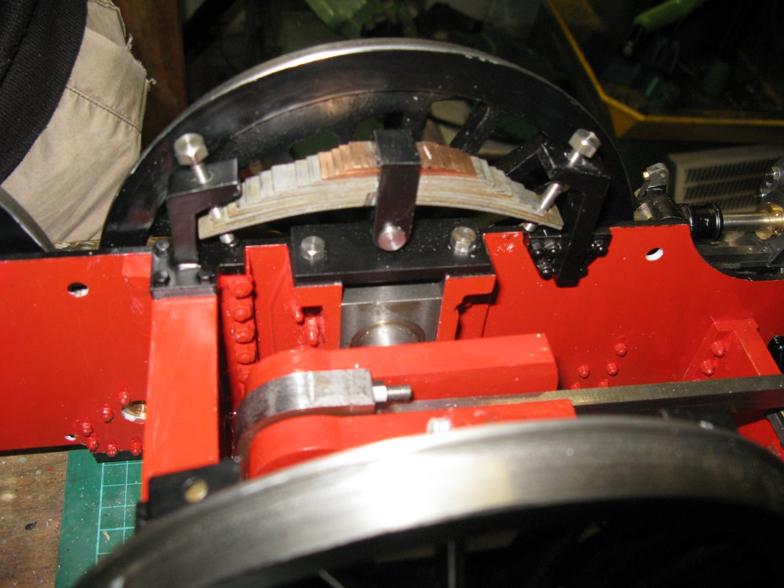
Springs on one axle fitted with shock absorbers.
You will notice the springs have not been painted. The reason for this is I want to lubricate the springs so the leafs slide easily against each other. Had I painted them it would have prevented the oil penetrating the leafs.
Just another two axles to fit.
Having fitted the remaining two axles and turned the loco onto its feet it naturally had a pronounced slope towards the front as that is where the weight is at the moment from the three cylinders. Of course without a bogie being there either to carry some of the front weight it was quite a natural thing to expect. So I cannot do any balancing of the axle weights until the loco is virtually complete with boiler fited etc. Likely to be some while away.
One thing I noticed having fitted all the springs was that if I had raised the axle boxes right to the top (upsidedown) the spring hanger pins might have been able to be fitted as drawn.
