This chapter covers the oiling lubrication points and the steam oil lubrication.
The first small job is the oiling arrangement for the middle and rear axle. This consists of two oil reservoirs on each side with a 3/32″ copper pipe from each to the axle boxes via the hornblocks.

The oil wells are made from 1/2″ square brass with a 5/16″ hole for the well reduced to 7/32″ at the bottom to clear the fixing holes

The wells have a hinged lid which is not shown on the drawing. Indeed no cap is shown at all.
The pipe run has a single P clip and is also held in place at the well end by superglue. The P clip is located as per drawing when the frames were drilled.
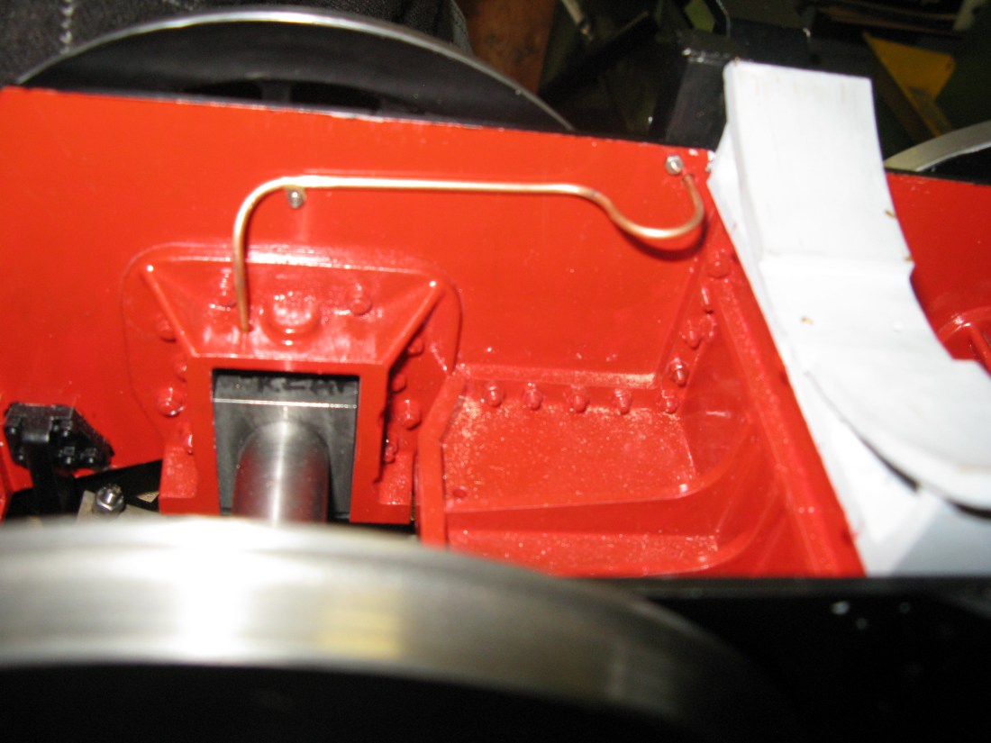
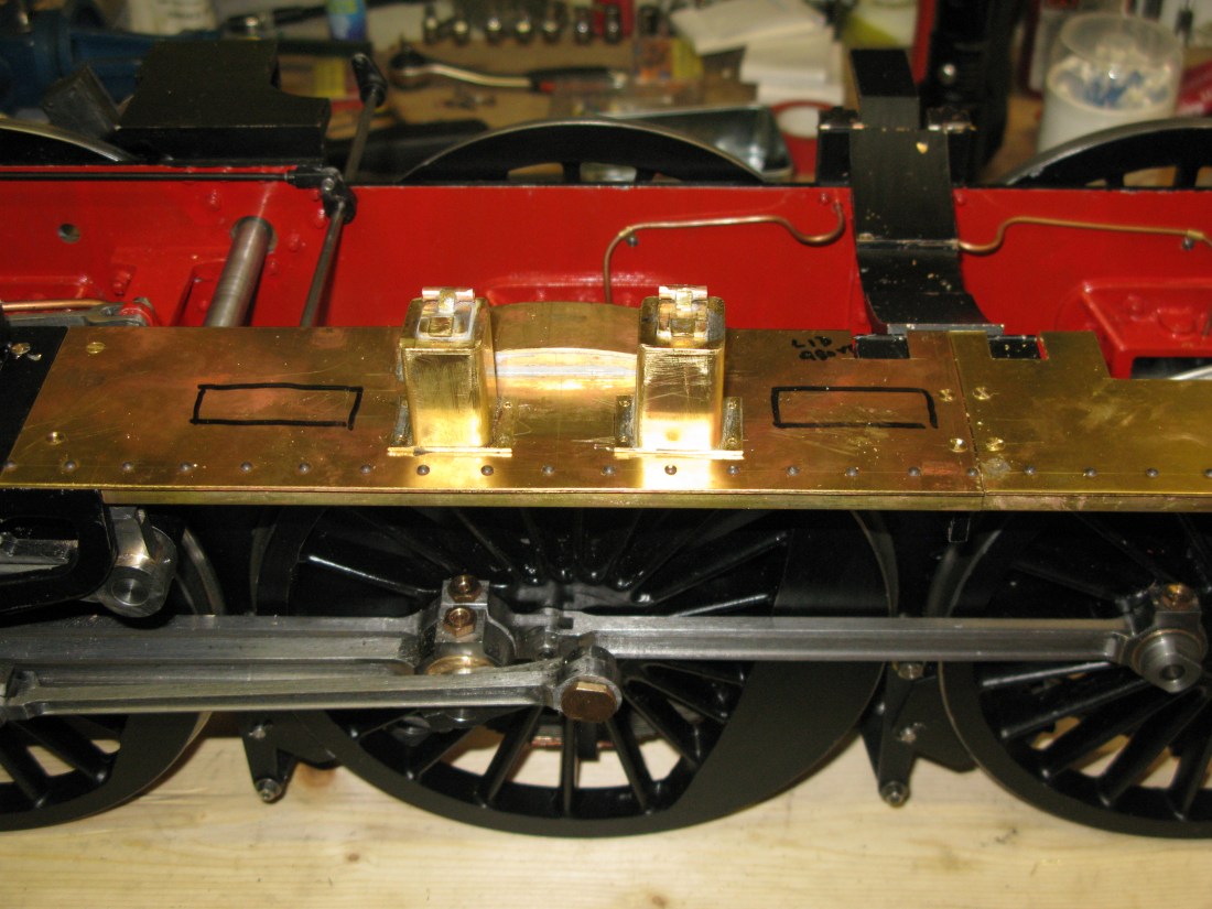
As drawn the well is fixed to the frame with 8 BA small HH screws from the inside, however as can be seen from the photo above the boiler support frame prevents this unless it is fitted before the frame is fitted. The gap between the boiler support and the main frame is less than a nut width so very slim nuts were produced to fit into the gap.
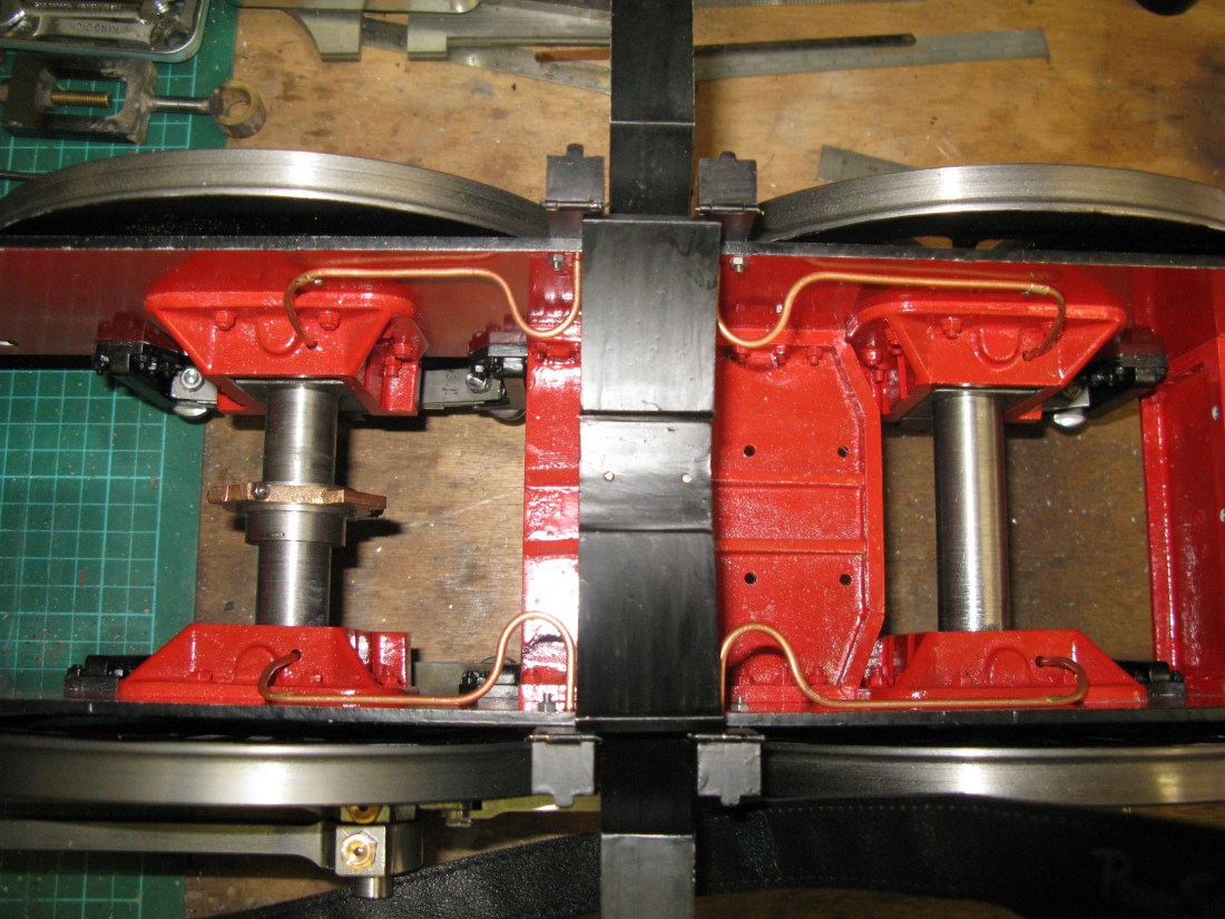
All four wells fitted and piped up. The bends away from the well are larger than drawn as this was the smallest pipe bender I had to hand.
A drop of oil in each well proved the pipework was free from obstruction as seen by the drips onto the axle boxes.
The axle boxes have matching holes to the pipe entry via the horn block for the oil to find its way onto the shaft.
Having fitted the wells I was suspicious they were too low and the running plate would be slightly higher. Checking the drawings again the wells and fixing holes are as drawn but one GA drawing shows them proud of the running plate by about 1/4″. Pity I had not spotted that ealier, but I am leaving it as is.
The steam oil lubrication is from a pump driven by an eccentric on the rear axle.
The pump is a commenrcial one I bought of the ratchet type. Sometimes buying a ready made item seems the right thing to do. However the pump needs modification in two aspects. Firstly it needs a bracket to fix it to the frames and secondly the lid has to have a pipe fitted to act as an oil filler masquerading as a sanding point.
The left hand frame has two c/s holes to take the bracket 7 BA fixing screws but there is a problem as one hole is just behind a wheel flange and a screw cannot enter from the outside so it has to be a nut on the outside to solve that problem.
The bracket was made from 20g brass and soldered to the pump body. Its offset was just sufficient to allow the pumb tank lid to be easily lifted off and on.

The link between pump and eccentric is a spring clevis on a screwed rod which in turn was soldered to a small bracket that screwed onto the strap.

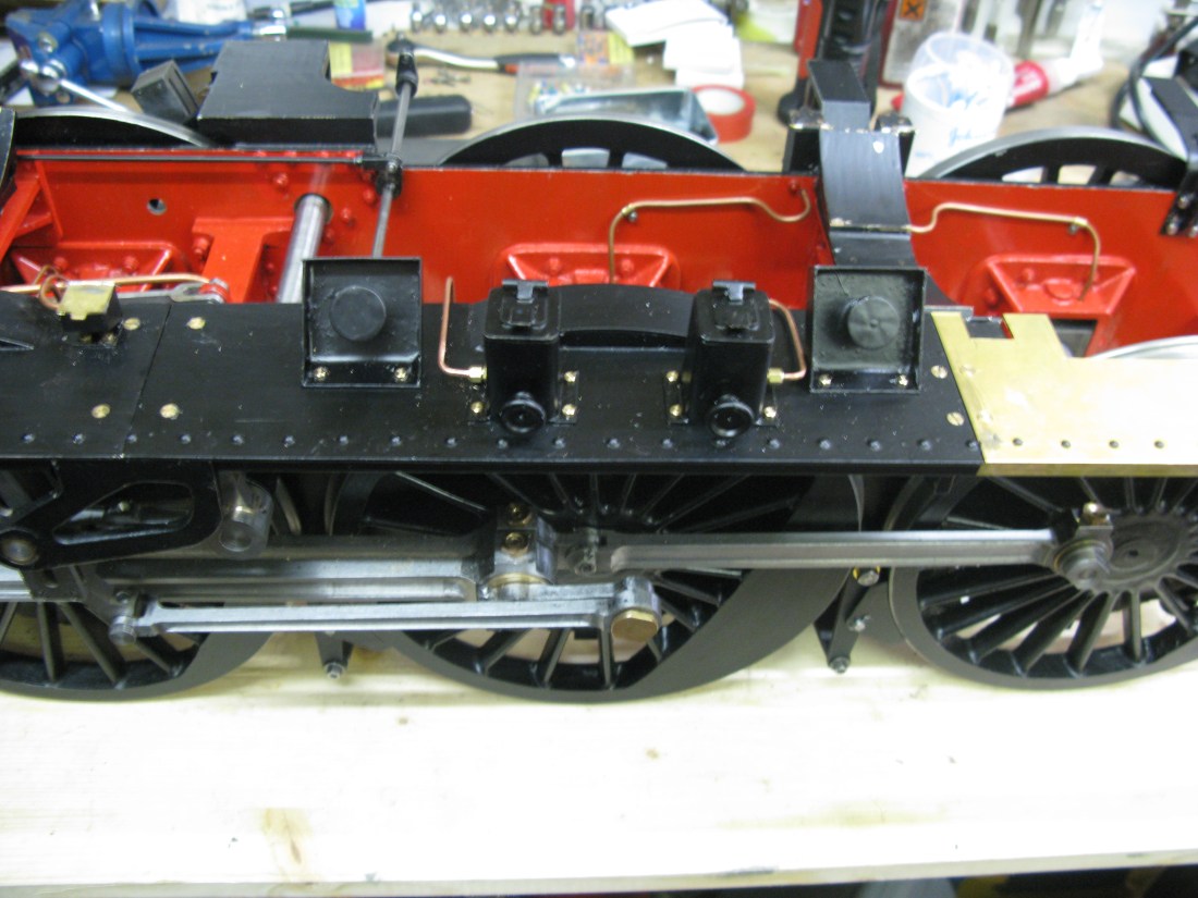
Lubricator pump and eccentric. Lid still to be modified to take filler pipe.
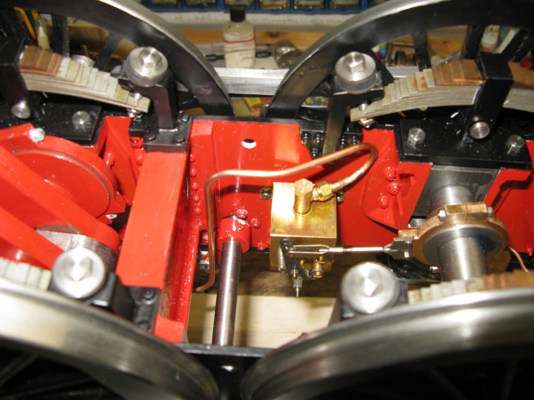
Pipe feed from the pump to cylinders
The lubrication pipe from the pump to the cylinders is 1/8″ copper and some thought had to be given to the pipework immediately feeding the cylinders. The drawing shows a simple cross piece with the feed in and three feeds out to the respective cylinders.
The cylinder feeds connect to non return valves fitted to the steam pipes just above the cylinder. Foe the outside cylinders this is fine but the inside cylinder would have the non return valve under the smokebox cradle and would be completely inaccessible should there be a need to access it. To overcome this I decided to fit the nonreturn valve outside of the cradle and this required a rearrangement of the pipework to accomodate its new position.

Arrangemnet of feed pipes to cylinders
The photo above shows my rearranged pipework. The smokebox cradle has a slot to accomodate the feed pipes to the middle cylinder. I did try to make the feed pipes of equal length as far as was practical to avoid the possibility of starvation occuring but the middle cylinder being farthest away was alway going to be longer unless I adopted a coil in all of the feed pipes to equal out the lengths.
The connection nipples soldered into the steam pipes are drawn with a 7/32″ x 40 tpi thread and so that’s how I made them. However commecial available fittings for 1/8″ pipe have nipples that have a 5/16″ x 40tpi retaining cap so all my connectors had to be custom made to fit 7/32″ x 40 tpi. Fortunately it was possible to make nipples to accomodate 1/8″ pipe with an acceptable wall thickness for silver soldering onto the pipe.
Details of the non return valve is written in the smokebox chapter as that is where the steam pipe connections are described.
There is a single oiling point for the front axle. The oil box is mounted on the running board and takes the same form as those for the other two axles in that it is a 1/2″ square oil box but mounted on a bracket. The oil pipe exits from the side and down to the axle box.

When the other side running boards are done there will be one on that side too.
There is an oil station just behind the steam pipe exiting the smoke box. On full size it has maybe 8 or 9 pipes eminating from it. On my model it will have three. One to lubricate the inside cylinder slide bars, one the crank pin and one for the eccentric on the inside cylinder valve gear. In terms of scale size I had to guess. There is no drawn component. The oil pipes are 1/16″ OD. There was no possibility of using the same size as the single axle oilers due to the size of the oil box and the room underneath its mounting to exit the pipes.
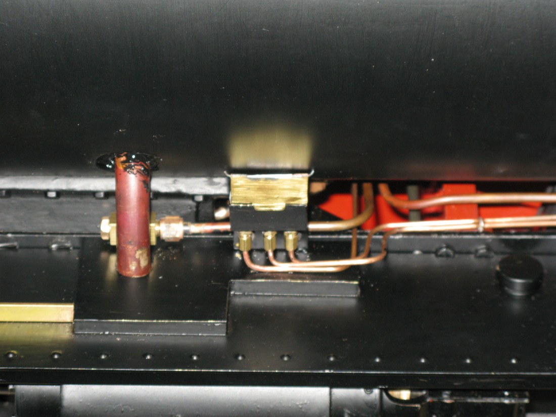
Having built and fitted the oil box I tried it out to see if the oil would actually flow down the 1/16″ pipes. I used a thin oil, but I did not know its viscosity number but it did not flow, well not in the time I left it. There was also a slight leak from one of the pipes connections.
The connections are too small for conventional nipples to fit on the pipe so it relies on a slight flare on the pipe end and hopefully the pipe then lines up with the hole in the fitting. Whilst the pipes were off I checked that the pipes were in fact not blocked. There did appear to blockage at the tight bend on the exit from the oil box. I did manage to get a small wire around the bend eventually and I will repeat the oil flow test but with Duck oil which I know is thinner than the one I used first time.
Having repeated the test with Duck oil one is free flowing and the other two are not so these need to be remade.
So the two blocked ones have been remade and fitted so the front lube oil is now working OK.

The cylinder lube oil lubricator is a commercial tank with ratchet pump fitted inside the frames. The filler is via a dummy sand box filler so the sand box brackets were made and fitted to the running board. Because of the error in the drawings not allowing for the sloping running boards a slot has to be filed in the running board for the filler tube.

Two dummy sand box fillers

The filler pipe is soldered to the lub oil tank lid and the cap is just a slid fit onto the tube. The filler pipe has to clear a retaining bush (just visible) and so is off centre on the lid.
There are two dummy lubricators also mounted on the running board. These are used to oil the eccentric for the cylinder oil ratchet drive.
The drawing calls for a pice of 3/4″ square brass drilled for the oil resevoir but I decide to make mine from folded brass sheet.
The lids are actually dummy as I was not happy the small hing arrangement would be lasting so the whole lid assembly lifts off. In the photo above the oil pipes have yet to be fitted.
The finished dummy lubricators with their oil pipes fitted. The right hand one feeds the cylinder oil lubricating pump eccentric and the left hand one goes to the crank axle making it two oil feeds on that item.
