After a long interval between finishing the tender and getting around to commissioning the loco a number of issues were found. I will relate them here in no particular order as they all result from a bit of a calamity.
Talking to a colleague who also has an A1 he advised that when doing a hydraulic trest it is necessary to clamp down the regulator valve to prevent leakage in to the superheaters etc. This is done with a screw in a spare dome fitting.
I tried my loco on air first and it held steady at 50 psi (my compressor capacity) with no leakage so I concluded that it would also be OK with a hydrauilic with water. It wasn’t. the regulator let by and as a result I had water in the cylinders. I drained everything down thinking I have to make the spare dome sometime and do as advised and set about making the tender.
A year later …… I bet you are now in front of me ……. having finished the tender I found the loco would not move. The wheels were solid. The diagnosis being rust in the cylinders. First attempts at pumping oil throught the draincocks plus a lot of manual pushing and shoving did produce some very stiff movement of sorts, but it was clearly not right. The cylinder block and valve cylinder end covers were removed and that revealed the extent of the rusting.
With the pistons and valves out of thier bores the damage was not as bad as first feared. A light honing was suficient to restore the bores to an acceptable condition. The valves were cleaned up (being steel) and the pistons being gunmmetal escaped with just the rings being given a light rub with fine emery paper.
Another area of rust was the drain cock rod levers within the chassis. These fit into the chassis without brass or PB bearings. Fortunately WD40 plus lot of oil freed them up to get the drain cocks moving freely again.
Reassembling all the pistons and valves showed the motion was really too stiff when turning the wheels by hand, this being accounted fo by the tighteness of putting the pistons and valves back in thier bores. So I decided to regap the rings by making a jig to accept the rings with a smaller gap and then heat treating them again. I coat the rings with Tipex correction fluid as this protects the metal from oxidising during the heat treatment and being a chalk (or somethink like it) base it wipes away afterwards easily.
Reassembling proved the motion to be a lot easier ( I hope I have not made the rings too loose now!).
During all the wheel turning with the tight motion A reversing gear lever driving the middle eccentric was found to be loose and slipping despite having two grub screws. Access to this without a boiler removeal was going to be difficult to put in a pin. However I did try and promptly managted to break a 1/16″ drill part way through drilling the hole. Of course the break did not allow me to get the broken bit out and it was not sufficient to act as a pin either. My next attempt was to grind a flat at an angle on the boss to meet the shaft. This gave better access to drilling and rather than drill a hole right through I chose to drill and tap a 4 BA hole to accept a 1/4″ long grub screw ensuring that it was half and half over the shaft to bush joint. This proved a success.
The reversing gear was now stiffer and there was still some slipping occuring somewhere. This turned out to be the shaft at the bottom of the reversing stand slipping on it connection to the reversing link into the stand. Another drilling exercise to fit a pinning grub screw as described above. With all the reversing linkages now solid the only play was in the reversing screw connection to the link at its bottom.
With all the putting in and taking out pistons and valve pistons it revealed that I had not put any packing in the glands. The pistons had 1/8″ graphite yarn put in as they were easily accessed. The valves would have to wait.
Whilst the loco was on its turnover stand I took the opprtunity to check the movement of the lubricating pump. Just as well I did as the ratchet driven pump did not have enough movement to turn the pump over. Maybe one click and not reliably. The problem could not be corrected by altering the length of the pump arm, the connection to the eccentric was already on its shortest position. The solution had to be removing the existing eccentric cam and making a new one with a larger throw. The existing cam had to be removed from the axle by cutting it into thirds so it could be taken off the axle easily. This was done with a cutting disc in a Dremmel tool. The new cam was larger in diameter to get the throw need but fortunatel not so large as to make a new strap necessary the existing one being bored out to fit. The eccentric was made with a split at the halfway point so it fitted over the axle and held in place by two clamping screws. That solved that problem.
The time then came to set the valves. With air connected to the boiler the plan was to check the air coming out of the drain cocks to ascertain the port opening and closing operation. This showed that tthe valve piston rings seemed to be letting by as air was coming out of the front cover end at a rate not relating to the exhaust. This unvield another problem. The piston valve bobbins as drawn (and made) are the exact length between the outer edges of the in and out ports, That’s OK I hear some say, but no, it is the rings that do the sealing not the bobbin and it is the outer edges of the rings that should cover both ports in mid gear. This meant that it was impossible to time the valves correctly and the bobbins would have to be modified so the outer rings covered both in and out port edges. This involved lengthening the bobbin by an amount equal to the sum of the widths of the end ring holders. (Remember my bobbins are of the split variety as the rings cannot be expanded to go over the bobbin diameter). This turned out to be a port width. The lengthening of the bobbin was achieved by splitting the middle part into two halves and inserting a spacer. To make the ports more accessible the end ring hoilders were chamfered to give a better steam flow passage. The result of lengthening the bobbin puts it off centre so to bring it back to a central position an amount was turned off the retaining collar at the motion end equal to half of the extension.
Having the valve on the middle cylinder in and out like a yoyo caused the gland nut to unscrew from the cylinder, the screwing in and out moved the gland nut by friction I guess, and of coures being the middle cylinder it is virtually inaccessible. However with lots of patience it was persuaded to screw back in again.
Timing of the valves still presented a problem so advice was sought on what to do.
It turned out that the two rings on the bobbin (each end) were too close together and there was no lap on the valves at all. The bobbin was redesigned to give lap and a 0.02″ lead with the valve movement existing with the motion. This gave port shut off but in full gear the port opening was very small as the available valve movement was shorter than needed for full port opening. This could not be corrected without a change to all the motion dimensions, a task too far. So i left the maximum port opening at 0.064″ which equates to 42% cut off. It ran OK on air with the modified bobbins although my compressor cannot supply enough air to keep it running.
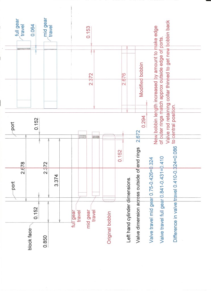
The image above shows the comparison of the as drawn bobbin and the modified version. Hopefully this explains the need for the cange to the bobbin design.
The engine was run on air with the the new bobbins and it self started and ran initially from 50 psi, but my compressor cannot deliver enough air to maintain running so as the pressure dropped the speed dropped away and eventually stopped.
During setting of the valves the return crank positions were checked but one was found to be moving and a number of attempts to tighten the clamp all failed. It turned out to be the crank pin moving in the wheel. It was not possible to remove the pin to allow a loctite joint to be made so a grub screw was inserted into a drilled and tapped hole at an angle at the base of the pin so it was in contact with both pin and wheel. That proved effective.
After a long time I have finally got around to continuing with the commissioning. The hydraulic was the first test to be done and this proved problematical as above 50 psi the regulator was still letting by despit being clamped down and there was leaking past the threads of the clamping screws. The leaks were resolved with a bit of sealing tape and pressure was eventually achieved but with minor leaks from some fittings. One blowdown valve was letting by and a couple of weaps from the clacks on the backhead. However it passed its hydrayulic test. Following the trest I tried to tighten the weeping blowdown valve and promptly sheared the valve off its pipe. So that put paid to doing the steam test. Looking at the regulator afterwards I could see there was enough room to put a sealing gasket between the valve and its seat for hydraulic testing on a future occasion. A club colleague said that what he does with his A1.
Having done a repair on the blowdown valve, next the steam test. I use paraffin soaked charcoal as a starter fire and this got away well with the blower running on 24 V. Once up to 50 psi it was struggling to get going further so I changed the blower to a larger volumetric one and that did the trick and pressure soon rose to nearly 100 psi but the safety valves were lifting and even with the adjustment screwed right down they were still lifting at 90 psi. (Working pressure is 100 psi). These were bought suitable for 100 psi and clearly were not good enough. The hot boiler soon found a couple of weeps on the backhead, same ones as the hydraulic that I gambled might seal under heat. They did’nt. The repaired blowdown valve had a slight weep from the new nipple fitted. The loco blower was totally useless in maintaining the fire and pressure and it was not until I got home and looked critically at the blower arrangement that I realised the blower rings were totally obstructed by the Kylchap structure and not only that, the rings were partially blocked. A New design was going to be required.
Testing the injectors was a failure too as there seemed not enough water was being drawn through by the steam. I suspected air leaks and there were two possible culprits, the hose not fitting tight enough on the connecting pipes and the water valve handle glands not sealing. I also wondered about the feed pipe size. Another job to see to.
So the steam test was a failure and remedial work is currently in hand.
The blowdown valave repair was straight forward resoldering of the nipple. Doing it in situe as the pipe with nut and nipple would not pass through the cab floor meant that some old plumbers mats used for insulating wall whilst a plumbing joint is made were pressed into use.
One of the clacks on the backhead that was weeping was removed, new sealant applied and refitted.
The blower was a redesign. I discarded the rings around the blast nozzle in favour of a single pipe up the center. This proved aomewhat difficult to fit as there is not much room between the blast nozzle and the bottom Kylchap skirt and the kylchap assembly remained in place whilst fitting. ( They are rather difficult and fiddly to fit so I did not want to take them out). The pipe is 1/8″ diameter and needs to be bent in a sort of S shape or chicane shape and to get into the kylchap void and then exit at the bottom at right angles into a block to connect to the blower steam pipe. It took a lot of faffing around and annealing to allow puruasive bending to get them both into thier respective Kylchap voids above the blast nozzles.
The tender water valves were modified from a screw down valve to a 90 degree turn on/off as the screw down typ needed 10 turns to be fully open. Not really practical. The new design fortunately could use the existing body. See below.
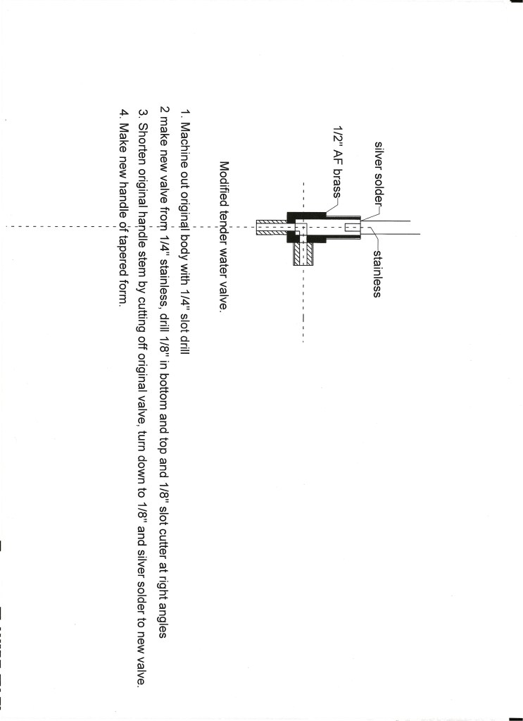
New hoses were also fitted with a smaller bore and they were a definite improvement.
However a test steam at home showed the injectors not working. Water was pulled through copiously as witnessed from the injector overflow, but no adjustment of steam or water flow would make them pick up. I suspect a blockage somewhere so they will have to come off to be investigated.
The test steaming showed the safety valves were now OK with their new springs so result there OK.
The leaky blowdown valve was not solved and it turned out to be a small amount of silver solder had run down on to the lip of the nipple so the nut was not closing the nipple on the cone connection evenly. A new nipple and nut were fitted, and there is still a weep!! to be eaxined yet again.
Another good resuslt was the blower. This worked fine in its modified form and kept a good fire going under stationary conditions.
The small weep on the blowdown nipple was solved with a bit of PTFE tape. However on steam test only one injector would pick up and that was at about 80 psi and would not pick up at operating pressure of 100 psi. The other failed completely. Plenty of water coming out the overflow but that was it.
The clack on the backhead that I resealed still leaked so that needed attention again. There were very small wisp coming from the brake valve connections and one gauge glass blowdown valve would’nt budge. So I abandoned the test and did not run with just one injector and hand pump.
Back home I removed the brake valve only to find it had siezed solid so that needs to be replaced by making a new one. The siezed gauge glass blowdown valve turned out to be impossible to remove so I resorted to having to remove the complete fitting only to damage it in the process, ( sod it!) so a new one has to be made. In removing it I did find the top of the glass had broken and although it was not leaking a new glass will be fitted.
With the fitting removed I managed to get the valve out and it had rusted. I had obviously used a bit of silver steel rather than stainless. Both are stocked near each other.
The leaking clack has been resealed again with a new crushable washer and sealent. Third time lucky?
The new brake valve has been made. However in making it I relied on the drawing which shows the steam to the brake cylinder and the exhaust at 90 degrees. This an error as these ports block off the fixing screws at the bottom. They can be put in during the assembly of the valve but it makes it difficult to use a spanner. I should have copied the original which had spotted this and the outlets are spread at a wider angle. C’est la vie. When the installed valve was tested on air by pumping up the boiler it was not sealing properly so on the basis that it was unlikely ever to be used I put a blanking plug (removeable) in the steam line connection. There is no room on the backhead for an isolating valve.
A new injector has been fitted to replace the one not picking up.
Another steam test due.
To be continued
